

Montarbo T10P, T12P, T15P, T18P Instruction Manual
T10P
T12P
T15P
T18P
passive loudspeaker systems

T18P / T15P / T12P / T10P
Passive loudspeaker systems
ITALIANO 3 - 6
ENGLISH 7 - 10
DEUTSCH 11 - 14
FRANÇAIS 15 - 18
ESPAÑOL 19 - 22
APPENDIX 23 - 29
September 2007

Passive loudspeaker systems
T18P
/
T15P / T12P / T10P
3
__________________________________________
__________________________________________
__________________________________________
__________________________________________
__________________________________________
__________________________________________
__________________________________________
__________________________________________
__________________________________________
__________________________________________
INDICE
Introduzione
Descrizione
Pannello connessioni
Importante !!!
Appendix
◗ Dati tecnici
◗
Schemi a blocchi
◗
Esempi di collegamento
◗
Parti di ricambio
4
4
5
6
23 - 29
24 - 25
25
26 - 27
28 - 29
ITALIANO
ITALIANO
Il punto esclamativo inserito in un triangolo equilatero avvisa l'utilizzatore della presenza
di importanti istruzioni per l'utilizzo e per la manutenzione nella documentazione che
accompagna il prodotto.
CONTENUTO DELL’IMBALLO
◗ Sistema passivo
◗ Cavo Jack-Jack
◗ Manuale istruzioni
◗ Certificato di garanzia
IMPORTANTE ! Norme di sicurezza
ATTENZIONE
Nell'interesse della propria e della altrui sicurezza, e per non
invalidare la garanzia, si raccomanda una attenta lettura di
questa sezione prima di adoperare il prodotto.
- Questo apparecchio è stato progettato e costruito per venire utilizzato
come sistema di altoparlanti nel contesto tipico di un sistema di
amplificazione sonora e/o di un sistema di registrazione sonora.
L’utilizzo per scopi diversi da questi non è contemplato dal costruttore, ed
avviene pertanto sotto la diretta responsabilità dell’utilizzatore/installatore.
PER EVITARE IL RISCHIO DI DANNEGGIAMENTO:
• Non esporre il prodotto alla pioggia, non utilizzarlo in presenza di elevata
umidità o vicino all’acqua. Non lasciare penetrare all’interno dell’apparecchio
alcun liquido, né alcun oggetto solido. In caso ciò avvenga, non utilizzare
l’apparecchio e rivolgersi ad un servizio di assistenza qualificato prima di
adoperarlo nuovamente.
• Collegare questo apparecchio esclusivamente alla presa di uscita di un
amplificatore di potenza o di un mixer amplificato. Utilizzare un cavo di
potenza (non schermato) di qualità adeguata e in buono stato.
• Prima di effettuare qualsiasi operazione di collegamento, assicurarsi che
l’amplificatore cui è collegato sia spento.
• Per scollegare l’apparecchio non tirare mai lungo il cavo, ma afferrarlo
sempre per il connettore.
ATTENZIONE!
Questo apparecchio non contiene parti interne destinate
all’intervento diretto da parte dell’utilizzatore.
Per evitare il rischio di danneggiamento, non aprirlo.
Per qualsiasi intervento di manutenzione o riparazione,
rivolgersi alla Elettronica Montarbo srl e/o a personale altamente
qualificato specificamente segnalato da questa.
- Nel predisporre l’apparecchio all’utilizzo, assicurarsi che la forma e la
portata della superficie di appoggio siano idonee a sostenerlo.
Nel caso si desideri installare la cassa su di un’asta di supporto, utilizzarne
una di portata adeguata al peso del prodotto, inserendola nell’apposito
adattatore.
Non tentare mai di appendere il prodotto con mezzi non espressamente
forniti o approvati dal costruttore (corde, catene, funi o qualsivoglia altro
mezzo, attraverso maniglie, bulloni, ganci etc.).
Nel caso il prodotto sia dotato già dalla fabbrica di specifici accessori,
verificare sempre, prima dell'installazione, che il sistema di sollevamento
e/o di sospensione che intendete utilizzare sia di portata idonea al peso
del prodotto.
Se il sistema viene semplicemente appoggiato ad un supporto, accertarsi
che la sua eventuale caduta non possa causare danni a persone o cose.
- Nell’installazione, accertarsi che i cavi di collegamento non costituiscano
intralcio o inciampo. Se possibile, non posarli mai in zone accessibili al
pubblico o al personale non qualificato. Se posati a terra in zone accessibili,
fissarli al pavimento mediante nastro adesivo o inserirli in idonei canali
passacavo. Assicurarsi che nessuno possa, urtando o inciampando in un
cavo di collegamento, causare la caduta del sistema di altoparlanti.
Qualora l’apparecchio venga utilizzato in presenza di bambini e animali,
si rende necessaria una strettissima sorveglianza.
- Questo prodotto è in grado di generare pressioni acustiche molto elevate,
pericolose per la salute del sistema uditivo. Evitarne quindi l’utilizzo ad elevati
livelli acustici se il pubblico si trova eccessivamente vicino al prodotto
(almeno ad 1 m di distanza).
☛ Non esporre i bambini a forti sorgenti sonore.

T18P / T15P / T12P / T10P
Passive loudspeaker systems
ITALIANO
4
Introduzione
I sistemi di altoparlanti T18P, T15P, T12P e T10P sono la risposta
alle necessità del pianobar, della piccola band o dell'orchestra
che richiede versatilità e prestazioni in una cassa compatta e
leggera. Le caratteristiche di base dei tre sistemi differiscono
per risposta in frequenza e pressione sonora massima.
Ognuno dei quattro sistemi incorpora un cross-over passivo di
alta qualità affiancato da un processore passivo che ottimizza
il rendimento e la linearità di risposta del sistema.
Descrizione
A Driver a compressione con gola da 1" e bobina da 2"
accop piato ad una tromba a direttività costante (90° H x 70° V)
che può essere ruotata di 90°.
B T18P: midrange 8".
T15P / T12P: midrange 6".
C T18P: woofer da 18" ad alta efficienza con magnete al
neodimio (bobina da 3")
T15P: woofer da 15" ad alta efficienza (bobina da 3")
T12P: woofer da 12" ad alta efficienza (bobina da 3")
T10P: woofer da 10" ad alta efficienza con magnete al
neodimio (bobina da 2,5")
D Cabinet in multistrato ad incollaggio fenolico con vernice
poliuretanica anti-graffio.
E Griglia in acciaio (verniciatura epossidica).
F Tubi di accordo.
G Due maniglie laterali per il trasporto nei mod. T18P, T15P e T12P,
una maniglia nella parte superiore della cassa nel modello T10P.
H Pannello connessioni.
I Adattatore per asta di supporto.
H
I
F
C
G
A
D
T15P
B
H
E
I
F
F
C
G
D
E
I
C
G
E
A
D
B
A
H
T12P
T10P
Le casse acustiche bass reflex T18P, T15P, T12P (a 3 vie) e T10P
(a 2 vie) incorporano componenti di alta qualità realizzati su
nostre specifiche.
■
potenze utilizzabili:
T18P: 500 W su 8 Ohm
T15P: 400 W su 8 Ohm
T12P: 400 W su 8 Ohm
T10P: 300 W su 8 Ohm
A
D
B
C
G
H
E
I
F
T18P
Passive loudspeaker systems
T18P
/
T15P / T12P / T10P
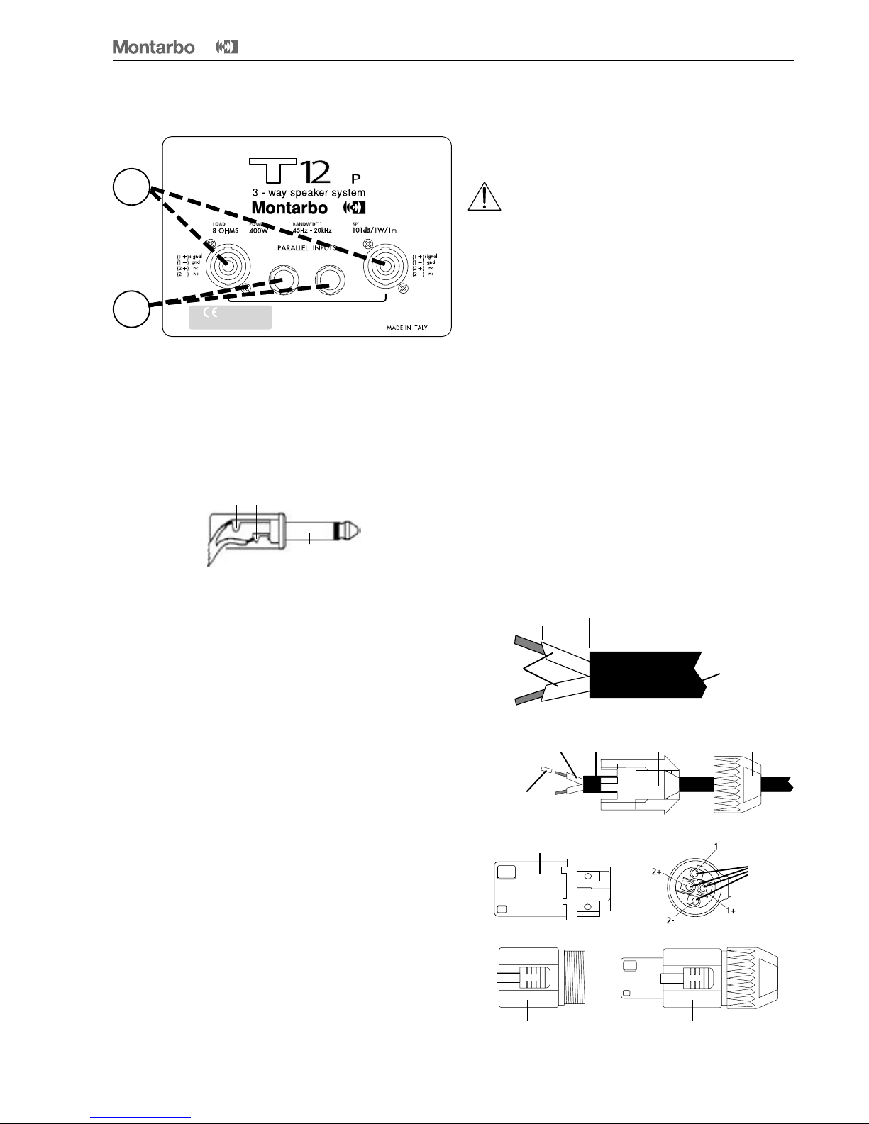
Pannello connessioni
Il pannello connessioni è uguale per tutti e quattro i modelli.
Sono utilizzabili sia connettori Jack che Speakon® per permettere la massima
flessibilità di collegamento. Le quattro prese sono in parallelo.
1 Prese Jack. Collegarne una (non importa quale) alla presa
di uscita dell’amplificatore di potenza o del mixer amplificato.
Utilizzare l’altra per collegare un secondo sistema di altoparlanti,
tenendo conto dell'impedenza totale.
2
Non collegare due amplificatori allo stesso sistema
di altoparlanti: questo potrebbe causare danni molto gravi
agli amplificatori.
1 GND = Massa
2 + = Caldo
Cablaggio del cavo di collegamento sul connettore Speakon®:
1 - Spelare il cavo per una lunghezza di 20 mm ed ogni singolo
filo per una lunghezza di 8 mm. Consigliamo l’utilizzo di un cavo
con conduttori aventi sezione di almeno 1,5÷2mm2 (i morsetti
dell’inserto possono comunque portare un cavo con fili aventi
sezione fino a 4mm2/12AWG).
2 - Infilare il cavo prima nella bussola poi nel serracavo (bianco
per un cavo con diametro 5÷11mm; nero per un cavo con diametro
9.50÷15mm). Terminare ogni singolo filo con un terminale ed
effettuare i collegamenti dei fili sull’inserto.
3 - I fili così terminati potranno essere serrati nei morsetti utilizzando
un cacciavite PZ1 oppure saldate, facendo attenzione ai simboli che
compaiono sul corpo del connettore stesso.
Collegare il filo positivo al morsetto contrassegnato 1 +, il negativo
al morsetto contrassegnato 1 -. Attenzione: i morsetti 2+ e 2- non
sono utilizzati.
4 - Effettuati i collegamenti sull’inserto infilarlo nel corpo e avvitare
quest’ultimo alla bussola.
Il connettore da utilizzare è un Neutrik Speakon® modello
NL4-FC. In alternativa, è possibile l’utilizzo del connettore
NL2-FC, che ha solamente i contatti 1+ e 1-.
CONNETTORE SPEAKON
®
CHIUSO
CORPO
BUSSOLASERRACAVO
CAVO
TERMINALE
FILI
1
2
3
4
CAVO
FILI
20 mm
8 mm
Connettore Jack non schermato
1 GND
2 + 2 +
1 GND
INSERTO
MORSETTI
VISTA INTERNA
2 Prese Speakon®: si consiglia di utilizzarle nelle installazioni più
critiche, in quanto il sistema di blocco del connettore ne impedisce
lo sfilamento accidentale.
1
5
ITALIANO
Neutrik Speakon® è un marchio Neutrik

T18P / T15P / T12P / T10P
Passive loudspeaker systems
Cura e manutenzione del prodotto
Per non compromettere il corretto funzionamento della cassa
acustica...
• Posizionare la cassa lontano da fonti di calore (caloriferi o qualsiasi
altro oggetto che produca calore).
• Evitare di esporre la cassa alla irradiazione solare diretta, ad
eccessive vibrazioni e ad urti violenti.
• Evitate l’uso ed il deposito dell’apparecchio in ambienti polverosi
o umidi: eviterete così cattivi funzionamenti e deterioramento
anticipato delle prestazioni.
• Proteggete l’apparecchio dal rovesciamento accidentale di
liquidi o sostanze di qualsiasi tipo. In particolare nelle condizioni
di utilizzo tipiche, prestare la massima attenzione alla collocazione
dell’apparecchio onde evitare che il pubblico, i musicisti, i tecnici
o chicchessia possa poggiarvi sopra bicchieri, tazze, contenitori di
cibo o di bevande, posacenere o sigarette accese.
• Non togliere la griglia di protezione dalla cassa.
• Per rimuovere la polvere usate un pennello o un soffio d’aria,
non usate mai detergenti, solventi o alcool.
• Abbiate cura dei cavi di collegamento, avvolgeteli evitando nodi e
torsioni.
• Non forzate i connettori.
• Prima di effettuare qualsiasi collegamento, accertarsi che
l’amplificatore o il mixer amplificato siano spenti.
Importante !!!
Collegamento alle PRESE DI INGRESSO
• Utilizzare solo cavi di potenza (non schermati) di adeguata sezione
(almeno 2 x 1 mm2) e qualità.
Non attorcigliare i cavi e non permettere che si formino nodi, che
potrebbero danneggiare l’isolamento.
• Nel caso si utilizzino le prese jack, verificare che i connettori siano
sufficientemente robusti e adatti all’impiego.
Non utilizzare connettori di scarsa qualità: potrebbero facilmente
causare corto circuiti e falsi contatti.
Collegamento in parallelo di più sistemi
• Collegare il secondo sistema al primo utilizzando una delle prese
libere. Tutte le prese possono esse-re utilizzate come ingresso o
uscita. Ovviamente è possibile collegare l’amplificatore al primo
sistema usando una presa jack e il primo sistema al secondo usando
una presa Speakon®, o viceversa.
• ATTENZIONE ALL’IMPEDENZA TOTALE:
se si collegano due sistemi in parallelo, l’amplificatore vedrà
una impedenza di carico di 4 Ohm, che è perfettamente
sopportata da tutti gli amplificatori e mixer amplificati
Montarbo e di quasi tutti gli altri costruttori.
Quando si collegano in parallelo 3 sistemi l’impedenza totale
scende a 2,7 Ohm; nel caso di 4 sistemi in parallelo a 2 Ohm.
Non tutti gli amplificatori di potenza o i mixer amplificati
possono funzionare con sicurezza con impedenze di carico
così basse.
Controllate le specifiche tecniche del vostro amplificatore o
del vostro mixer amplificato.
ITALIANO
6
Passive loudspeaker systems
T18P
/
T15P / T12P / T10P
__________________________________________
__________________________________________
__________________________________________
__________________________________________
__________________________________________
__________________________________________
__________________________________________
__________________________________________
__________________________________________
__________________________________________
7
ENGLISH
8
8
9
10
23 - 29
24 - 25
25
26 - 27
28 - 29
ENGLISH
INDEX
Introduction
Description
Connection panel
Important !!!
Appendix
◗ Specifications
◗
Block diagrams
◗
Connection examples
◗
Spare parts
The exclamation point in an equilateral triangle, is intended to alert the user to the presence
of important operating and maintenance instructions in the literature accompanying the
product.
PACKAGE CONTENTS
◗ Passive system
◗ Jack to Jack cable
◗ Owner’s manual
◗ Warranty certificate
IMPORTANT ! SAFETY INSTRUCTIONS
WARNING
In order to protect your own and others' safety and to avoid
invalidation of the warranty of this product, please read this section
carefully before operating this product.
- This product has been designed and manufactured to be operated as a
speaker system in the typical applications of a sound reinforcement system
or of a sound recording system. Operation for purposes other than these is
not provided for by the manufacturer and is therefore to be undertaken at
the end user’s and/or installer’s sole risk and responsability.
TO AVOID THE RISK OF DAMAGE:
• Never expose this product to rain or moisture, never use it in proximity
of water or in high humidity conditions. Never let any liquid, as well as
any object, penetrate the product. Should this be the case, do not use the
speaker system and refer to qualified servicing before operating it again.
• This product must be connected only to the output of a power amplifier
or a powered mixer. Always use a good quality speaker cable (unscreened),
and check it frequently for any damage to insulation and connectors.
• Before moving the product after it has been installed, or while it is
operating, make sure that the power amplifier is switched off.
• To disconnect this product from connecting cable never pull the cable
directly: hold it by the plug instead.
CAUTION!
This product does not contain user serviceable parts.
To prevent damage never open it. For maintenance and
repairs interventions always refer to the official
Montarbo Distributor in your State or to qualified personnel
specifically authorised by the Distributor.
- Before placing the product on a surface of any kind, make sure that its
shape and load rating safely match the product size and weight.
When installing the speaker system on a stand, use a stable stand that will
fit in the adapter and may carry the loudspeaker weight.
Never attempt to hang the product by any means not expressly provided or
approved by the manufacturer (i.e. ropes, chains, belts or whatever medium,
throgh carring handles, bolts, hooks or whatever).
In case the product is factory-fitted with specific mounting hardware, always
verify before installation that the lifting and/or hanging system you intend to
use is of a proper type and can carry the product weight with the safety ratio
required by the regulations in force.
If the speaker is simply placed on a support, make sure that it won't cause
injure or damage if knocked down.
- When setting up the speakers, make sure that the connecting cables do
not create any obstruction or danger. As a general rule, never lay them
down in any area that may be accessed by the audience or by unqualified
personnel. If they are laid on the floor in an accessible area, secure them to
the floor using adhesive tape (“gaffa” tape) or insert them in a suitable
cable channel. Make sure that in no case the speaker system can fall down
because someone has pushed or stumbled over a speaker cable.
In case the product is used near children and animals closest supervision is
necessary.
- This product can generate very high acoustic pressures which are
dangerous for the hearing system. Always avoid operation at loud levels
if anyone is excessively near to the product (at least 1 m of distance).
☛ Never expose children to high sound sources.

T18P / T15P / T12P / T10P
Passive loudspeaker systems
Introduction
The T18P, T15P, T12P and T10P loudspeaker systems are
designed to meet the stringest requirements in versatility,
ruggedness and sonic performances for mid-size applications.
These compact, lightweight systems differ only for frequency
response and max. sound pressure.
Each of them is fitted with a high quality passive cross-over
network together with a passive controller that linearizes
and protects the loudspeakers.
8
ENGLISH
A 1" compression driver (2" voice coil) coupled with a constant
directivity horn (90°H x 70°V) which may be rotated 90°.
B T18P: 8" Midrange
T15P / T12P: 6" Midrange
C T18P: 18" high efficiency neodymium magnet woofer
(3" voice coil)
T15P: 15" high efficiency woofer (3" voice coil)
T12P: 12" high efficiency woofer (3" voice coil)
T10P: 10" high efficiency neodymium magnet woofer
(2,5" voice coil)
D High grade multiply cabinet with highly resistant antiscratch
polyurethane paint finish.
E Perforated steel grid (epoxy resin finished).
F Tuning ports.
G Two side transport handles in models T18P, T15P and T12P
one transport handle on the upper side in model T10P.
H Connection panel.
I Speaker stand adaptor.
Description
H
I
F
C
G
A
D
T15P
B
H
E
I
F
F
C
G
D
E
I
C
G
E
A
D
B
A
H
T12P
T10P
A
D
B
C
G
H
E
I
F
T18P
The 3-way (T18P / T15P / T12P) and 2-way (T10P) bass reflex
enclosures house high quality components custom designed
to our specifications.
■
power handling:
T18P: 500 W into 8 Ohms
T15P: 400 W into 8 Ohms
T12P: 400 W into 8 Ohms
T10P: 300 W into 8 Ohms
Passive loudspeaker systems
T18P
/
T15P / T12P / T10P
9
ENGLISH
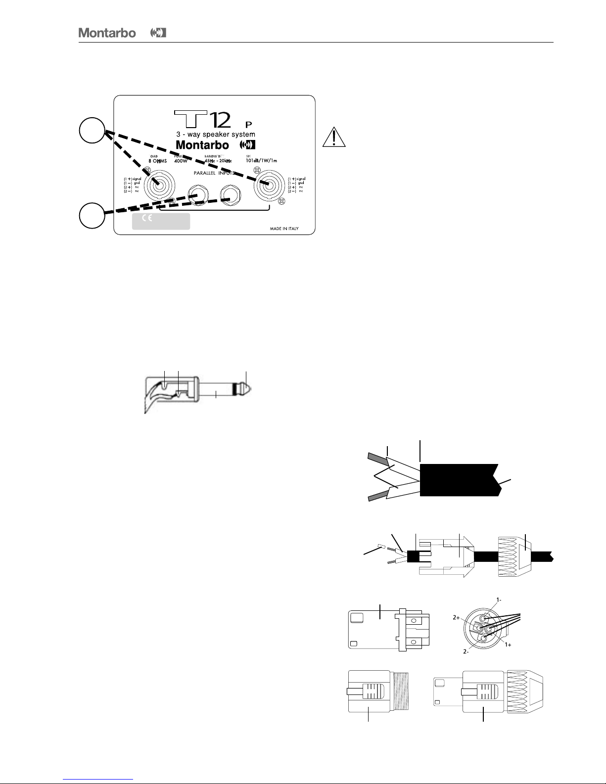
Connection panel
Connections are the same for the four models.
The system is fitted with both Jack and Speakon® connectors to achieve
maximum flexibility. The four sockets are connected in parallel.
1
Input jack sockets: they are best suited for mobile (touring)
applications or when it is expected to frequently disconnect the
system. Use one of them (at your choice) for connection to the
power amplifier or the powered mixer output. Use the other one‚
if needed, for parallel connection of another speaker system.
Always pay attention to the total impedance.
The trademark Neutrik Speakon® is property of Neutrik
2
1
Never connect two power amplifiers to the same
speaker system: doing this may result in serious damage
to the amplifiers.
2
Speakon® connectors: this is the better choice for critical
installations, because the locking connector avoids accidental
disconnection.
1 GND = Ground
2 + = Hot
1 GND
2 + 2 +
1 GND
Wiring of the connection cable to the Speakon® connector:
1 - Strip the cable for 20 mm of length and strip each wire for
8 mm of length . We suggest to use a cable with 1,5 ÷ 2mm2
section wires (the insert terminals are however suitable for a cable
with wires up to a section of 4mm2/12AWG).
2 - Insert the cable into the bushing and into the chuck (white chuck
for a cable diameter of 5 ÷ 11mm; black chuck for a cable diameter
of 9.50 ÷ 15mm).
Fit a ferrule at the end of each wire and connect wires on the insert.
3 - The wire ends can be clamped in the terminals using a PZ1
screwdriver or soldered. Always pay attention to the symbols
shown on the connector body ! : connect the positive wire to the
terminal labelled 1+, the negative wire to the terminal labelled 1- .
Terminals 2+ and 2- are not used.
4 - After connecting the wires to the insert, lead it through the
body and screw down the body with the bushing.
Mating connector is a Neutrik Speakon® model NL4-FC.
If not available, model NL2-FC may be used: this version has
contacts 1+ and 1- only.
SPEAKON
®
CONNECTOR
HOUSING
BUSHINGCHUCK
CABLE
FERRULES FOR
STRANDS
WIRES
INSIDE VIEW
INSERT
SETSCREWS
1
2
3
4
CABLE
WIRES
20 mm
8 mm
Unscreened Jack connector
 Loading...