

Montarbo Spot 2500T User Manual

1
PROFESSIONAL LOUDSPEAKER SYSTEM
user's manual
ENGLISH
PROFESSIONAL LOUDSPEAKER SYSTEM PROFESSIONAL LOUDSPEAKER SYSTEM
2
user's manual
ENGLISH
IMPORTANT ! SAFETY INSTRUCTIONS
WARNING
In order to protect your own and others' safety and to avoid invalidation
of thewarranty of this product, please read this section carefully before
operating this product.
- This product has been designed and manufactured for being operated as a speaker
system in the applications typical of a sound reinforcement system.
Operation for purposes and in applications other than these has not been covered by
the manufacturer in the design of the product, and is therefore to be undertaken at end
user's and/or installer's sole risk and responsibility.
- This unit conforms to Class I insulation, and for safe use it is required that the
protective earth contact is connected to a grounded (earthed) outlet.
TO AVOID THE RISK OF FIRE AND/OR ELECTRIC SHOCK:
• Never expose these products to rain or moisture, never use it in proximity of water or
on a wet surface. Avoid dripping water or water sprays, moreover never place objects full
of liquid, such as vases, on top of it. Never let any liquid, as well as any object, enter the
products. In case, immediately disconnect it from the mains supply and refer to servicing
before operating it again. Never place burning candles or other sources of open flame
on top of the device. Keep clean and free from dust the ventilation grids on rear panel.
• Before connecting this product to the mains supply, always make sure that the voltage
on the mains outlet corresponds to that stated on the product.
• This product must be connected only to a grounded mains outlet complying to the
safety regulations in force via a power cable of adequate copper section terminated with
a plug or a connector complying with all safety regulation applicable.
In case the power cable needs to be substituted, use exclusively a cable of the same type
and characteristics.
Refer to page 14 for detailed instructions about mains connector's wiring.
• This device is connected to the power line even when the mains switch is off.
As long as it is plugged in there are dangerous electrical potentials inside the device, so,
before undertaking any sort of maintenance work etc., always make sure it has been
unplugged from the mains socket.
• Never place any object on the power cable. Never lay the power cable on a walkway
where one could trip over it. Never press or pinch it.
• Never install the product without providing adequate airow to cool it.
Never obstruct the air intake openings on it. In xed installations, leave enough room
to get to the mains power socket and the mains connector on the back panel.
• Always make sure the Power switch is in its '0' (= off) position before doing any
operation on the connections of the product.
• Before attempting to move the product after it has been installed, remove all the
connections.
• To disconnect the power cable of this product from the mains supply never pull the
cable directly. Hold the body of the plug firmly and pull it gently from the mains supply
outlet.
CAUTION!
This products does not contain user serviceable parts.
To prevent fire and/or electrical shock, never disassemble it or remove the rear panel.
For maintenance and servicing always refer to the official Montarbo Distributor in your
Country or to qualified personnel specifically authorized by the Distributor.
- When setting-up the system for operation, make sure that the shape and load rating
of the surface or the structures that will support it can safely match the product size
and weight.
- To avoid shocks, kicks, or whatever action, always reserve a protected area with
no access to unqualified personnel as installation site of the product.
- In case the product is used near children and animals closest supervision is necessary.
- This product can generate very high acoustic pressures which are dangerous for the
hearing system. Always avoid operation at loud levels if anyone is excessively near to
the product.
* Never expose children to high sound pressures.
The lighting ash with arrowhead
symbol within an equilateral triangle,
is intended to alert the user to the
presence of uninsulated "dangerous
voltage" within the product's
enclosure, that may be of sufficient
magnitude to constitute a risk
of electric shock to humans.
The exclamation point within an
equilateral triangle, is intended
to alert the user to the presence
of important operating and
maintenance (servicing) instructions.
3
ENGLISH
user's manual
TABLE OF
CONTENTS
PA CKAG E
CONTENTS
The SPOT2500T system is delivered in two, individually packaged elements.
one SPOT15B package containing:
- model 15B passive bass cabinet
- model 15B warranty certicate
one SPOT2500T package containing:
- model SPOT2500T full-range active cabinet
- ac power supply cabletted with PowerCon
®
connector
- cable for the bass cabinet to full-range cabinet connection
- SPOT2500T system user's manual
- SPOT2500T warranty certicate
- CE declaration of conformity
1 - INTRODUCTION AND APPLICATIONS ........................................................4
1.1 - Introduction to SPOT2500T .............................................................4
1.2 - SPOT2500T applications ..................................................................4
2 - SYSTEM'S COMPONENTS .....................................................................5 - 9
2.1 - SPOT2500T - full-range active cabinet ........................................... 5
2.2 - SPOT2500T - model SPOT15B passive bass cabinet ......................9
3 - INSTALLATION AND WIRING ............................................................10 - 17
3.1 - Installation .....................................................................................10
3.2 - AC mains supply cable ..................................................................13
3.2.1 - Wiring of POWERCON
®
connector ...................................14
3.3 - System wiring ................................................................................15
3.3.1 - Wiring of signal cables ......................................................15
3.3.2 - Wiring of SPEAKON
®
connectors ......................................16
3.4 - Parallel connection of multiple systems ...................................... 17
4 - OPERATION ........................................................................................18 - 20
4.1 - Powering on ...................................................................................18
4.2 - Loading a Preset from control panel ............................................18
4.3 - Connection to a Personal Computer ............................................ 20
5 - RAConLS SOFTWARE ........................................................................21 - 35
5.1 - Hardware requirements ................................................................ 21
5.2 - Installation .....................................................................................21
5.3 - Using the program ........................................................................29
5.3.1 - Building the speaker's list .................................................31
5.3.2 - Main controller window ...................................................32
5.3.3 - Management of presets ....................................................35
6 - PRODUCT'S CARE AND MAINTENANCE ..................................................36
7 - SPOT2500T BLOCK DIAGRAM ................................................................. 37
8 - TECHNICAL DATA .....................................................................................38
Thank you for the preference you have shown by purchasing the Montarbo
®
SPOT2500T system.
This manual contains important information about installing and operating the product correctly and safely.
Read this manual carefully in order to thoroughly familiarize yourself with these procedures.
PROFESSIONAL LOUDSPEAKER SYSTEM PROFESSIONAL LOUDSPEAKER SYSTEM
4
user's manual
ENGLISH
1 - INTRODUCTION AND APPLICATIONS
1.1 - INTRODUCTION TO SPOT2500T
The SPOT2500T active speaker system features a revolutionary new concept
in acoustic and electronic design characterized by painstaking attention in
terms of component selection, materials and production techniques.
The result is a product of absolutely contemporary, essential and rigorous
design, with great attention to detail.
All the system’s drivers, designed with great attention to every detail and
custom-built specically for this system, are equipped with the most
efcient and powerful motor assemblies available on the market today:
- woofers with neodymium magnets and long excursion, large diameter
voice coils
- controlled directivity wave-guide horns coupled to neodymium drivers
with very high magnetic ux.
Very high levels of performance, despite their remarkably small size and
low weight, thanks to power ampliers with digital technology controlled
by a dedicated Montarbo DSP processor.
The processor (56 bit, 180 MHz, 24 bit converters) takes care of the ltering,
equalization, delay, limiter and diagnostic functions, while optimizing the
system’s power and linearity. It utilizes an advanced algorithm for the
real-time control of both the power output and temperature (both internal
and external) of the amplier, thus increasing the system’s overall reliability.
5 presets are available, one of which may be customized by the user, thus
adapting the speaker’s acoustic response to the user’s personal taste.
A dedicated software program that was developed in our R&D laboratory
makes it possible to operate the speaker on a remote control basis by
means of a Personal Computer and our LD24 USB interface.
With a single LD24 USB interface it is possible to operate up to 10 speaker
systems by remote control.
The remote control allows: programming and storage of custom presets in
the PC; a 10 lter “fully parametric” equalizer; adjustment of the delay and
output level of each speaker system; monitoring of the power amplier’s
condition (temperature, protection circuits, limiters and thermal alarms);
a dedicated standby function which reduces power consumption when no
signal is present.
The control software makes these systems extremely exible.
In xed installations the ability to adjust the delay and equalizer make it
possible to align the sound system’s phase and frequency response
1.2 - SPOT2500T APPLICATIONS
The "quasi-tree-way" SPOT2500T system performs at extraordinarily high
levels whenever especially outstanding dynamics are required.
The typical application for this system is the coverage of large areas when
budgetary or technical reasons don’t allow for a suspended line-array
system. These systems were designed to simplify the task of assembling
clusters by simply placing multiple enclosures side-by-side when wider
horizontal dispersion is required, maintaining tonal coherence and
interference-free horizontal wave-front summing.
When it is not possible to place the speaker systems on the stage floor, the
SPOT 2500T may be placed at ground level and the full-range cabinet may
installed on top of the bass cabinet by means of a dedicated coupling bar.
It may also be used for stage-monitoring applications (in-fill system) and as
the 'resident' system in theatres and in live-performances venues.
5
CAUTION !
AVIS !
LINK IN SUB OUT
1
2
3
4
User
Preset
Both = Enter
VOL.
SPOT 15 OUT
1000W
Sub
2
1
sig clip thw
prot
DATA
POWER
AC LINE IN AC LOOP OUT
Internal Fuse
2500W
230V 50/60Hz
a
b
c
e
f
g
i
h
d
ENGLISH
user's manual
2 - SYSTEM'S COMPONENTS
SPOT2500T is a 'quasi 3-way' active tri-amplied speaker system composed
of two modules: a full-range cabinet and a bass cabinet.
- The full-range cabinet SPOT2500T incorporates all the electronics needed
to process and power the whole system: three class-D amplifiers (with
switching power supplies) that can supply a total of 2500 Watts EIAJ
managed by the Montarbo DSP.
The system is equipped with:
- two 15” woofers, one of which is enclosed in the passive bass module.
Both feature a 4” voce coil and a powerful, shielded, neodymium
magnet. The magnet is front-mounted, allowing for improved cooling
under power-intensive conditions;
- one HF driver with a 1.4” throat and 3” voice coil, featuring a neodymium
magnet and titanium diaphragm, loaded by a high directivity wave-guide
horn. The horn has a very low cut-off frequency, resulting in improved
far-field intelligibility.
2.1 - SPOT2500T - full-range active cabinet
a - 1 x
15” woofer
, with
a 4” voce coil and a powerful, shielded,
neodymium, front-mounted, magnet
.
b -
one HF driver with a 1.4” throat and 3” voice coil, featuring a
neodymium magnet and titanium diaphragm, loaded by a high
directivity (50°H x 40°V) wave-guide horn
.
c - Cabinet made from birch plywood, with high-impact, chip-resistant paint.
d - Steel protection grill with foam protection.
e -
Bass reex vents
.
f - Carrying handles.
g -
Controls and connections panel
.
h - Speaker-stand adapter.
i - M10 threaded inserts.

PROFESSIONAL LOUDSPEAKER SYSTEM PROFESSIONAL LOUDSPEAKER SYSTEM
6
1
8
3
7
5
9
4 6
2
user's manual
ENGLISH
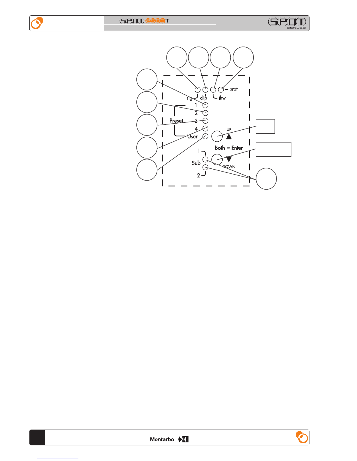
SPOT2500T - CONTROLS AND CONNECTIONS PANEL
7
ENGLISH
user's manual
CONTROLS AND CONNECTIONS PANEL
1 - AC LINE IN: ac line input connector.
This is the mains supply inlet socket with type A PowerCon® (blue)
connector which guarantees a reliable, vibration-proof contact.
Connect it to the mains socket using only a mains cable with suitable
conductors capable of handling the current involved, equipped with a
ground conductor, marked with the applicable, country specic, safety
approvals and tted with a power plug certied for the actual current
value. Refer to par. 3.2 for connector wiring instructions.
When installing the speaker system, make sure that it is easy to get to this
socket and to the mains plug.
2 - AC LOOP OUT: power link connector.
This type B (gray) PowerCon
®
connector allows you to link other devices
to the mains power (max current available: 13,6A).
Refer to par. 3.2 for connector wiring instructions.
Maximum current available from this connector is limited. Refer to par. 3.2.
3 - Mains ON/OFF switch.
Even when the switch is in the 0 (off) position, the AC LOOP OUT
connector (2) is connected to the mains power. Devices connected to it
must be switched off by means of their power switches.
4 - Input connector.
It is a balanced, line level input, that may be fed by balanced or
unbalanced sources. Connect it to the mixer output. It is a 3-pin female XLR
connector, balanced. For wiring details, refer to par. 3.3.1.
5 - Input link connector. It is wired in parallel to the input connector (4) and
it makes possible to send the input signal to other equipment (usually to
other self-powered speaker systems). For wiring details refer to par. 3.3.1.
For details about parallel connection of multiple systems, refer to par. 3.4.
6 - Master volume control that adjusts the system's volume (of both full-
range and bass cabinets).
7 - RJ45 sockets of the two DATA ports: they are intended for connection
to the Montarbo USBNet control network: a Montarbo LD2.4 USBNet
interface and/or another active speaker of the FULL, SPOT and WIDE series.
Use standard 8 poles ETHERNET cables (CAT5 or higher).
For more detailed information, refer to par. 4.3.
8 - SUB OUT socket for driving an external active sub-woofer.
By selecting the suitable preset (refer to par. 4.2) the internal DSP may be
congured to drive a subwoofer with or without an internal crossover
lter. In the rst case the output is a wide-band signal, in the second case
the output is band-limited and suitable for most active sub-woofers.
It is a 3-pin male XLR connector.
Refer to par. 3.3.1 for wiring details.
9 - SPEAKON
®
socket for the connection of the SPOT15B bass cabinet.
Use the supplied cable.
If a longer cable is needed, it may be assembled following the wiring
instruction of par. 3.3.2.
PROFESSIONAL LOUDSPEAKER SYSTEM PROFESSIONAL LOUDSPEAKER SYSTEM
8
A
p1
p2
p3
p4
p0
B C D
u p
d o w n
E
user's manual
ENGLISH
SPOT2500T - DSP CONTROLS
DSP CONTROLS
A - Green LED 'sig' (signal): it lights up when an input signal is detected.
B - Red LED 'clip': it lights up when a clipping (excess of signal level) is
detected in the input stage of the internal DSP. If this indicator ashes
frequently or is always on, reduce the input level, acting on the volume
control (6) or on the mixer's output gain control.
C - Yellow LED 'thw' (thermal warning): when lit, it indicates that the
temperature of the internal power ampliers is close to, or higher than,
the attention threshold: the internal microprocessor is analyzing the available energy. It is a normal behavior for this LED to ash even in absence
of input signal. For a correct operation, check periodically (monthly) the
rear panel's ventilation grills and verify that they are free of obstructions.
Also check that the speaker's temperature is not too high due to proximity
to heat sources or because subjected to direct radiation from the sun.
D - Red LED 'prot' (protection): this led indicates the intervention of the
protection circuit of the internal power ampliers. The reason may be an
excess in terms of temperature, of output current or a uctuation in mains
supply value (lighting strikes or brown outs). The LED comes on even if
the speaker has been muted by remote control, via the RAConLS software
program (refer to par. 5.3).
P1 - P2 - P3 - P4 - P0: these LEDs show the active Preset.
P1 - P2 - P3 - P4 are the factory (default) preset, P0 is the user preset.
The four LEDs P1 - P2 - P3 - P4 come on when the speaker has been muted
by remote control (refer to par. 5.3).-
UP - DOWN: these pushbuttons allow for preset selection.
For a description of the presets and how to load them refer to par. 4.2.
E - Green 'Sub 1' and 'Sub 2' LEDs: when on, they indicate that the SUB
OUT output is active and what type of sub-woofer drive signal has been
selected (refer to par. 4.2).
9
l
p
o
n
q
r
m
1+/1 signal
2+/2 nc
9
ENGLISH
user's manual
CONNECTION PANEL
9 - SPEAKON® socket for the
connection to the full-range active
cabinet. Connect to the '8' socket.
Use the supplied cable.
If a longer cable is needed, it may be
assembled following the wiring
instruction of par. 3.3.2.
SPOT15B - CONNECTION PANEL
2.2 - SPOT2500T - model SPOT15B passive bass cabinet
l - 1 x
15” woofer
, with
a 4” voce coil and a powerful, shielded,
neodymium, front-mounted, magnet
.
m - Cabinet made from birch plywood, with high-impact, chip-resistant paint.
n - Steel protection grill with foam protection.
o - Bass reex vents.
p - Carrying handles.
q - Connection panel.
r - Speaker-stand adapter.
PROFESSIONAL LOUDSPEAKER SYSTEM PROFESSIONAL LOUDSPEAKER SYSTEM
10
POLE MOUNTING: Preset P1
STACKED: Preset P2
DIPOLE: Preset P3
CLUSTER: Preset P4
user's manual
ENGLISH
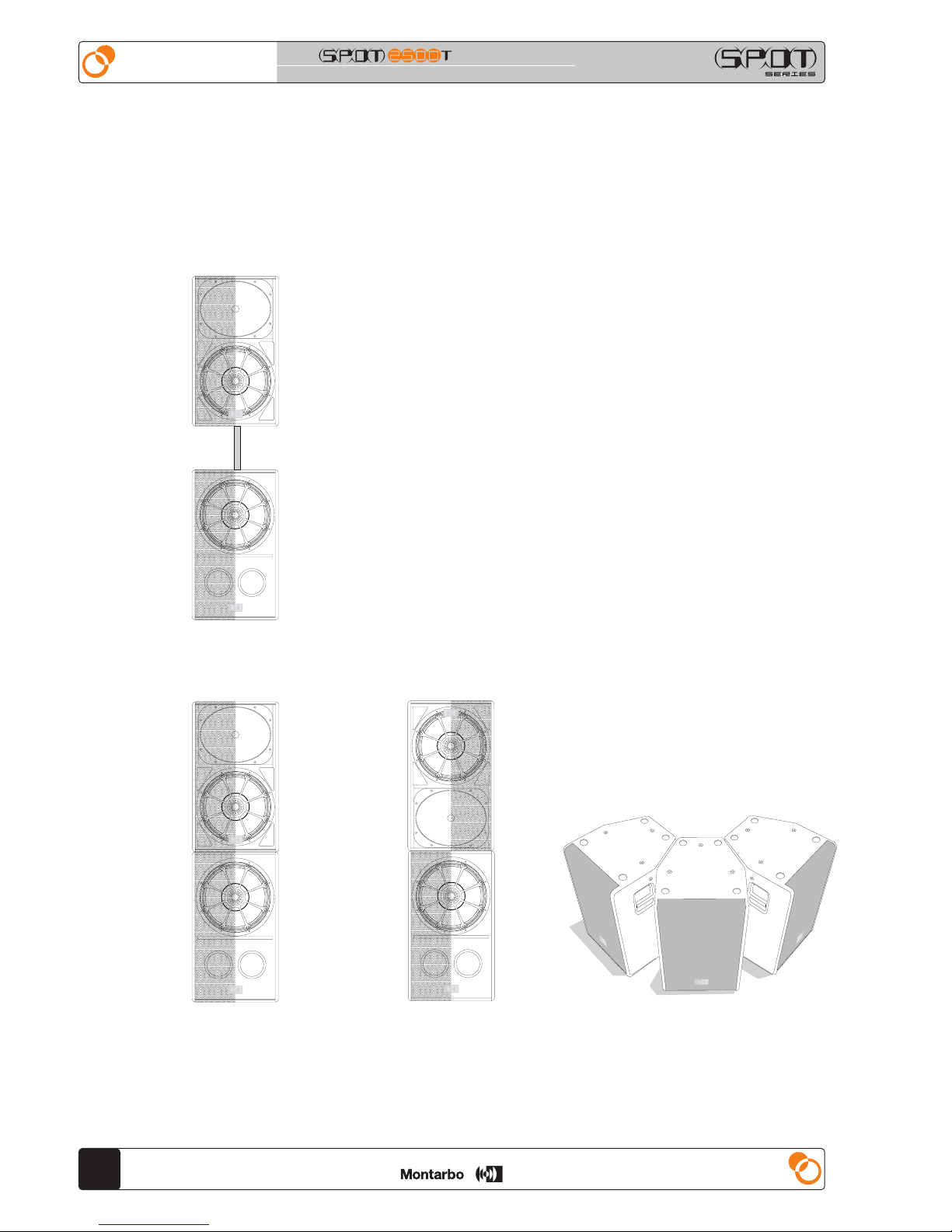
3 - INSTALLATION AND WIRING
3.1 - INSTALLATION
The full-range SPOT2500T speakers may be installed in various ways,
and the internal DSP presets allow to optimize their performances in the
various configurations.
- They may be installed over of the SPOT15B bass cabinet, using the SM3
dedicated mounting pole (optional accessory) fitted in the built-in adapters
(h: page 5 and q: page 9) - 'Pole Mounting' conguration, P1 preset.
- They may be placed on stage ground or stacked over the SPOT15B bass
cabinet -'Stacked' conguration, P2 preset.
- The may be stacked upside-down over the SPOT15B bass cabinet, thus
creating a dipole conguration that will result in increased sound pressure
at low frequencies -'Dipole' conguration, P3 preset.
- They may be placed side-by-side to create a 'cluster' of two or more
speakers, thus extending the horizontal dispersion without creating
wave-front interferences - 'Cluster' conguration, P4 preset.
For each one of these congurations, illustrated in the following gures, a
dedicated factory preset is provided in the internal DSP (refer to par. 4.1).
11
2500W
AIN
S
ENGLISH
user's manual
Make sure that the installation position is a protected one so that the
cables cannot be trampled or tripped on.
Make sure that the shape and load rating of the mounting surface are
suitable for a safe installation.
If the system is placed over a surface, make sure that the cables are placed
in a protected position to avoid the risk of the speakers falling over if
somebody trips over the.
The M10 threaded inserts (i: page 5) are intended for xed installation
by means of standard or custom-made mounting accessories.
For a safe installation is mandatory that these accessories are specified
to safely support the speaker weight .
It is the installer's responsibility to verify that the installation's safety has
not been compromised.
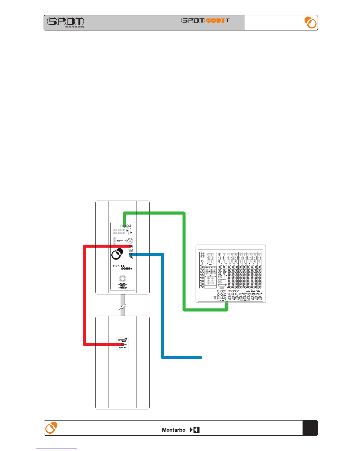
Wire the system's components as described in the following gure.
PROFESSIONAL LOUDSPEAKER SYSTEM PROFESSIONAL LOUDSPEAKER SYSTEM
12
user's manual
ENGLISH
AC mains connection
• Make sure the mains power switch is off ('0').
• Check that mains voltage corresponds to the voltage indicated on the panel.
• Use only the factory supplied mains cable or, if a different plug style is
needed, a suitable cable with a ground connection and marked with the
safety approvals valid in the country of use.
• Leave enough room to get to the mains power socket and the mains
connector on the back panel. As long as it is plugged in there can be
dangerous electrical potentials inside the device, even when the mains
switch is in the '0' (off) position and the power indicator is off so, before
undertaking any sort of maintenance work etc., always make sure it has
been unplugged from the mains socket.
For details about mains power cable and ac link cable wiring,
refer to par. 3.2.
Connection to mixer
• If the mixer has XLR balanced outputs: use standard balanced XLR
connectors.
• If the mixer has XLR unbalanced outputs: in this case, unless using a
Montarbo mixer, make sure that the XLR outputs on the mixer are
unbalanced to IEC 268 standard 1 = GND, 2 = HOT, 3 = GND.
• If the mixer has JACK balanced outputs (stereo jacks):
it is possible to use stereo jack-XLR adapters, wired according to IEC 268,
pin 1 = ground (sleeve), pin 2 = tip, pin 3 = ring.
• If the mixer has JACK unbalanced outputs (mono jacks): use suitable
Jack-XLR male adapters unbalanced according to IEC 268 pin 1 = ground,
pin 2 = tip, pin 3 = ground.
Connection of the full-range cabinet SPOT2500T to the bass cabinet
SPOT15B
Use the cable supplied with the system.
If longer cables are needed, they may be assembled following the wiring
instruction of par. 3.3.2.
Connection to a sub-woofer
• If the sub-woofer has an XLR balanced input (female): use a standard
balanced XLR cable (male-female).
• If the subwoofer has an XLR unbalanced input: make sure that the input is
unbalanced according to IEC 268 standard 1 = ground, 2 = hot, 3 = ground.
• If the sub-woofer has a JACK balanced input (stereo jack):
it is possible to use a stereo jack-XLR adapter, wired according to IEC 268
pin 1 = ground (sleeve), pin 2 = tip, pin 3 = ring.
• If the sub-woofer has a JACK unbalanced input (mono jack):
use suitable Jack-XLR female adapter unbalanced according to IEC 268
pin 1 = ground, pin 2 = tip, pin 3 = ground.
• Always use only heavy gauge, high quality SHIELDED cables (signal cables).
• Always make sure that the mixer and the powered enclosures are
switched off before connecting them.
This will avoid annoying noises and signal peaks, which can also be
dangerous for the enclosures themselves.
For details about signal cables wiring, refer to par. 3.3.1.
 Loading...