

Montarbo PALCO PLUS User Manual

1
PROFESSIONAL ARRAY SYSTEM
italiano | english
manuale utente | user’s manual
user’s manualuser’s manual
user’s manualuser’s manual
41
1 - AN INTRODUCTION TO "LINE ARRAY" SPEAKER SYSTEMS ...........42 - 43
1.1 - What makes a lot of stacked speakers boxes a Line-Array ........42
1.2 - Reproduction of low frequencies .................................................43
2 - SYSTEM COMPONENTS ....................................................................44 - 47
2.1 - RA16 - loudspeaker .......................................................................44
2.2 - BUMPER - model B1 .......................................................................45
2.3 - BUMPER LIGHT - model B2 ............................................................45
2.4 - RAB1815 - cardioid sub-bass .........................................................46
2.5 - LM24 - digital controller ................................................................47
2.6 - PLM6800 - 'powered controller' 4-channel power amplifier
with digital loudspeaker management ...............................................47
2.7 - EASE FOCUS - Aiming Software ...................................................47
3 - RIGGING THE SYSTEM ......................................................................48 - 49
3.1 - Safety standards and regulations ................................................ 49
3.2 - Safety checks and inspections ......................................................49
4 - SETTING-UP AND ASSEMBLING THE ARRAY ...................................50 - 55
5 - SYSTEM WIRING ................................................................................56 - 68
6 - POWER AMPLIFIERS SELECTION .......................................................69 - 70
6.1 - PLM6800 - 4-channel power amplifier with digital loudspeaker
management .........................................................................................70
7 - EASE FOCUS AIMING SOFTWARE ....................................................71 - 72
7.1 - Notes about operating system .....................................................71
7.2 - Installation .....................................................................................71
7.3 - Program's overview ......................................................................71
8 - PALCOPLUS SYSTEM TECHNICAL DATA ...........................................73 - 74
APPENDIX ......................................................................................................76
Safety and compliance certification of system's components
INDEX
english english
42
user’s manualuser’s manual
1 - AN INTRODUCTION TO "LINE ARRAY"
SPEAKER SYSTEMS
This document describes the operating principles of the PALCOPLUS
line-array system, as well as its main applications and features.
While not intended to be a complete technical essay about line-array
systems, this chapter will provide a brief summary of the basic theory of
operation and of the benefits of line array systems.
The following chapters will offer a description of the PALCOPLUS system
and its applications, including wiring and flying information.
Understanding the physical principals that determinate the behavior
of these systems will allow the user to optimize its application in mobile
or fixed installations.
The desired result from any sound reinforcement system is high sound
pressure and uniform coverage over the audience area.
This objective has often been addressed by using more powerful speakers, or
a larger number of them.
The problems encountered using this strategy are well known.
Line array systems use a different approach to solve these problems.
1.1 - WHAT MAKES A LOT OF STACKED SPEAKER BOXES A "LINE-ARRAY"?
The simplest definition of a "line array" is: a number of special independent
units (loudspeakers), vertically stacked and aligned, that operate as a single
sound source and which provide coherent summing, if some conditions
are met.
The vertical stacking achieves a sound field that has a narrow vertical
coverage, with higher directivity and sound pressure than conventional
systems.
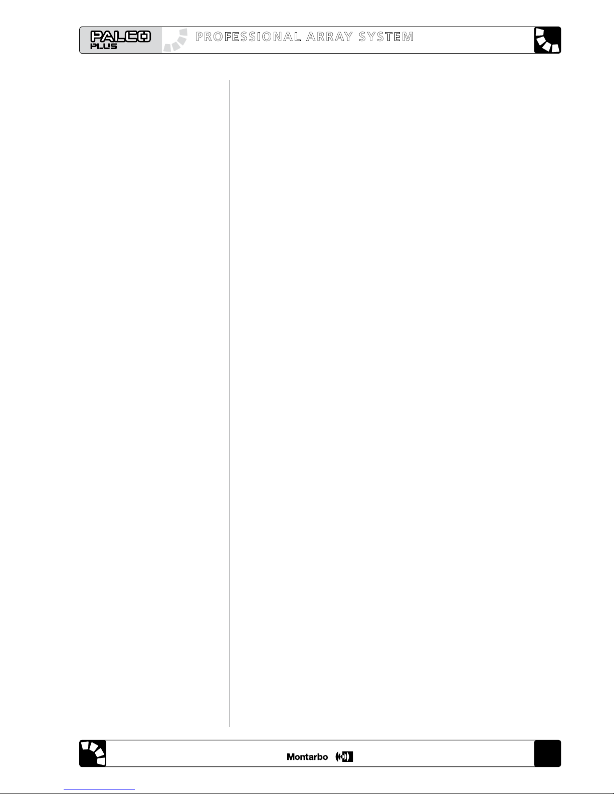
The sound waves emitted are referred as "cylindrical waves" (figure 1), and
they attenuate only 3 dB for every doubling of the distance from the source,
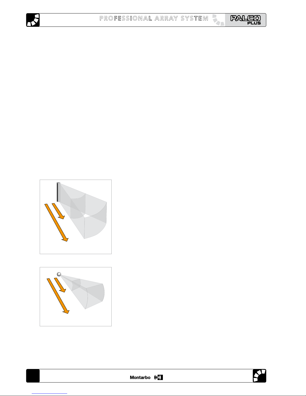
as opposed to the "spherical waves" (figure 2) emitted by conventional
loudspeakers, which attenuate 6 dB for every doubling of distance.
This is true up to a distance from the source which is dependent upon its
frequency and the height of the array, thus the longer the array is made
(building it with more loudspeakers) the longer the throw of the system.
Cylindrical waves only expand in the horizontal plane, not in the vertical
plane. The area doubles every time the radius (distance from the source) is
doubled, which is equivalent to a loss of pressure of only 3 dB.
2R
R
A
2A
4A
A
2R
R
Figure 2. Spherical wave
Figure 1. Cylindrical wave
user’s manualuser’s manual
user’s manualuser’s manual
43
The loudspeakers ("elements") that make up a "line-array" must meet a
certain set of conditions for the effects to be coherent and acceptable over
a wide frequency range:
1 - The distance between the acoustic centers of the various elements
must be equal to or lower than half the wavelength corresponding to the
maximum frequency to be reproduced.
This means that an array made with small cabinets fitted with small
loudspeakers may be effective to a higher frequency (it is for this reason
that the PALCOPLUS RA16 loudspeaker is fitted with 8" woofers). This is
true for frequencies that are higher than a critical one, that is a function
of the array length. This means that, in order to correctly generate lowfrequency cylindrical waves, the array must be very long.
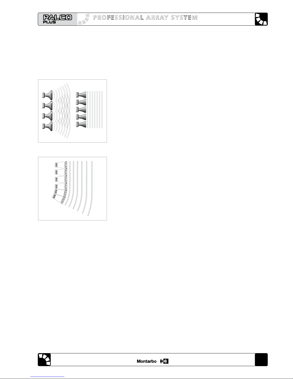
2 - The separation between the high frequency radiators (wave-guides)
must be minimal: the wave-guides must be tightly spaced. This is the
reason that the array is assembled by tightly coupling the front of the
loudspeakers. The wave-guides must be of special design, because the
sound waves emitted must be time-coherent: they must generate plane
waves. In this way there is no disruptive interference (figure 3 - A) between
radiation from the separate wave-guides: they generate plane waves that
sum coherently (figure 3 - B).
The theoretical line array should be a straight line, but in many cases this
cannot be done, especially when the array must be flown.
A flown, straight array will not give adequate coverage throughout the
audience area and, in practice, it may be necessary to curve the array in
order to achieve sufficient coverage of the nearest areas.
This result in a J-shaped array, where the upper speakers (in a straight line)
are used for the long-throw coverage and the lower speakers, in a curved
line, are used for the short-throw coverage (figure 4).
Each speaker that makes up the line array must incorporate a rigging
system that allows aiming in the vertical plane.
The rigging system, usually an integral part of the units, allows for hinging
at the front of the box so that the separation between the speakers stays
the same, while the rear plates allow for adjusting the angle between
speakers ("splay" angle).
A software program is used to determine the correct angle between the
various speakers of the array. Starting from the geometry of the venue, the
desired coverage and the number of speakers available, this program will
give the correct splay angle between the speakers and the correct rigging
point. For the PALCOPLUS system we supply the custom EASE FOCUS
software.
1.2 - REPRODUCTION OF LOW FREQUENCIES
For the reasons explained above, a line-array's low frequency reproduction
is limited by the array's length (and by it's components).
Special low frequency units are thus used.
To extend the response to the lowest octaves, the PALCOPLUS system
utilizes a specially designed sub-bass unit, model RAB1815.
It's two low frequency woofers, an 18" and a 15", are acoustically loaded
in different ways, while the geometry of the system and the frequency and
phase correction supplied by the LM24 digital controller or by the digital
controller integrated into the PLM6800 'powered controller' transform it
into a directive low-frequency source, with a cardioid directivity pattern.
The RAB1815, due to it's size and weigh, is not intended to be flown.
Figure 3. Plane waves: coherent
radiation of multiple wave-guides
AB
Figure 4. Radiation of a curved
array
english english
44
user’s manualuser’s manual
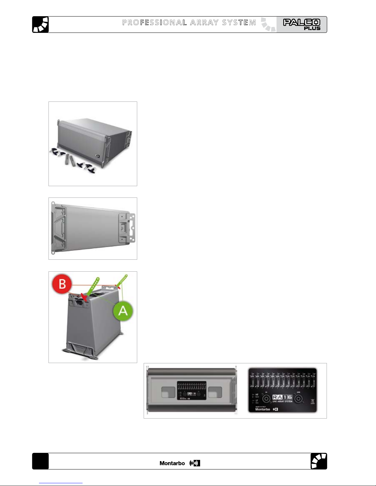
Figure 6. Integral rigging system
Figure 5. RA16
Figure 7. Vertical angle
adjustment bars and quick
release pins
Figure 8. RA16 Rear panel
2 - SYSTEM COMPONENTS
The PALCOPLUS line array is a system, made up of different components
that must be used together for maximum results:
- RA16 - enclosure
- BUMPER (model B1 or B2)
- RAB1815 - cardioid sub-bass unit
- LM24 - digital controller (with RACon PC software) or, as an alternative,
- PLM6800 'powered controller' 4-channel power amplifier
- LD2.4 - USB interface
- EASE Focus - Aiming Software
2.1 - RA16 - enclosure (figure 5)
Two-way speaker system, equipped with 2 woofers in a dipole
configuration (8" with 2.5" moving coil, neodymium magnet) and an
HF driver with a 3" titanium diaphragm, neodymium magnet, loaded
by a plane wave guide with 1.4" throat.
The cabinet is built from tough 15 mm Finnish birch with a special coating
providing very high resistance to abrasion; it weights just 18 kg, including
the special steel suspension fittings (figure 6).
For each speaker an external power amplifier is specified, with at least
800 W / 8 ohms for the woofers and 200 W / 16 ohms for the driver.
A two channel amplifier (1600 W / 4 ohm per channel) is suitable for
driving two units.
The frequency range is 70 Hz ÷ 20 kHz, the crossover is at 800 Hz,
24 dB/octave.
Each enclosure is supplied with:
- 2 rear steel plates that allow the assembly of the enclosures in the array
and for adjusting the vertical splay angle between units (figure 7 - A).
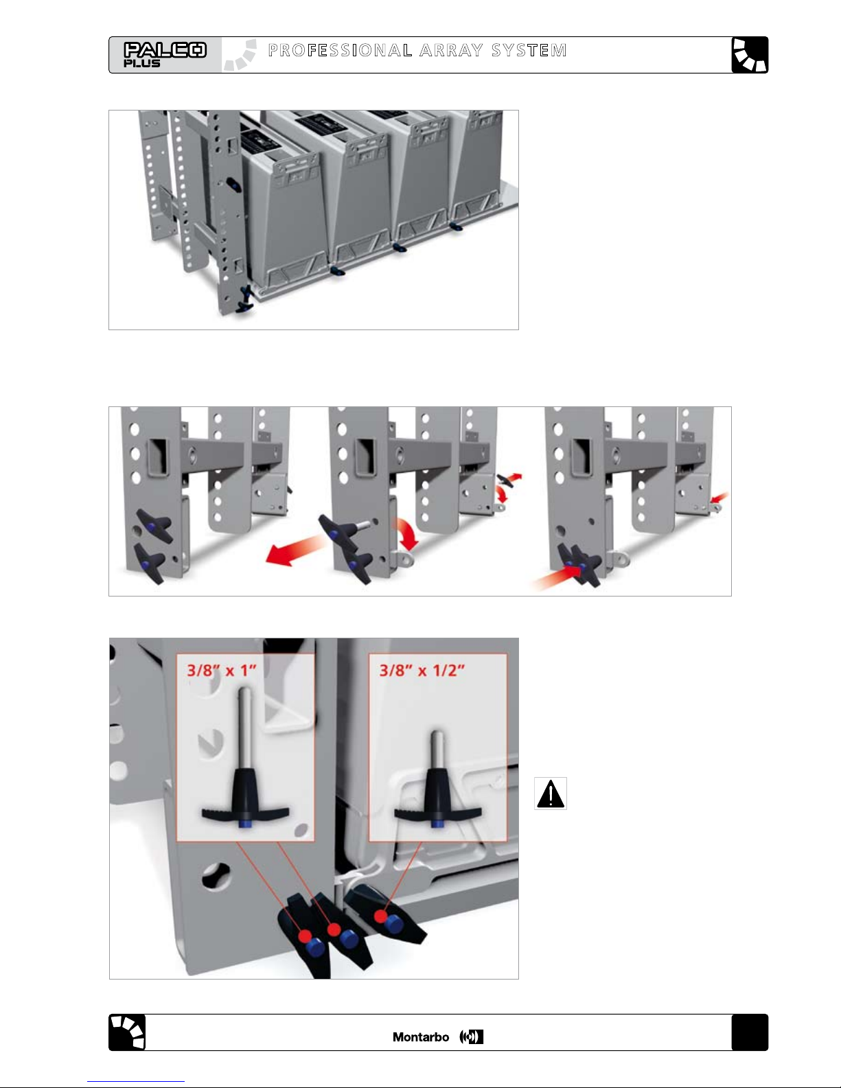
- 6 highly resistant quick release pins (figure 7 - B) with ball safety lock
(3/8" x 1/2").
Connection to power amplifiers is by a 4-pole
n e u t r i k s p e a k o n
®
socket.
A second socket allows parallel connection of a second speaker (figure 8).
Refer to chapter 5 for wiring details.
user’s manualuser’s manual
user’s manualuser’s manual
45
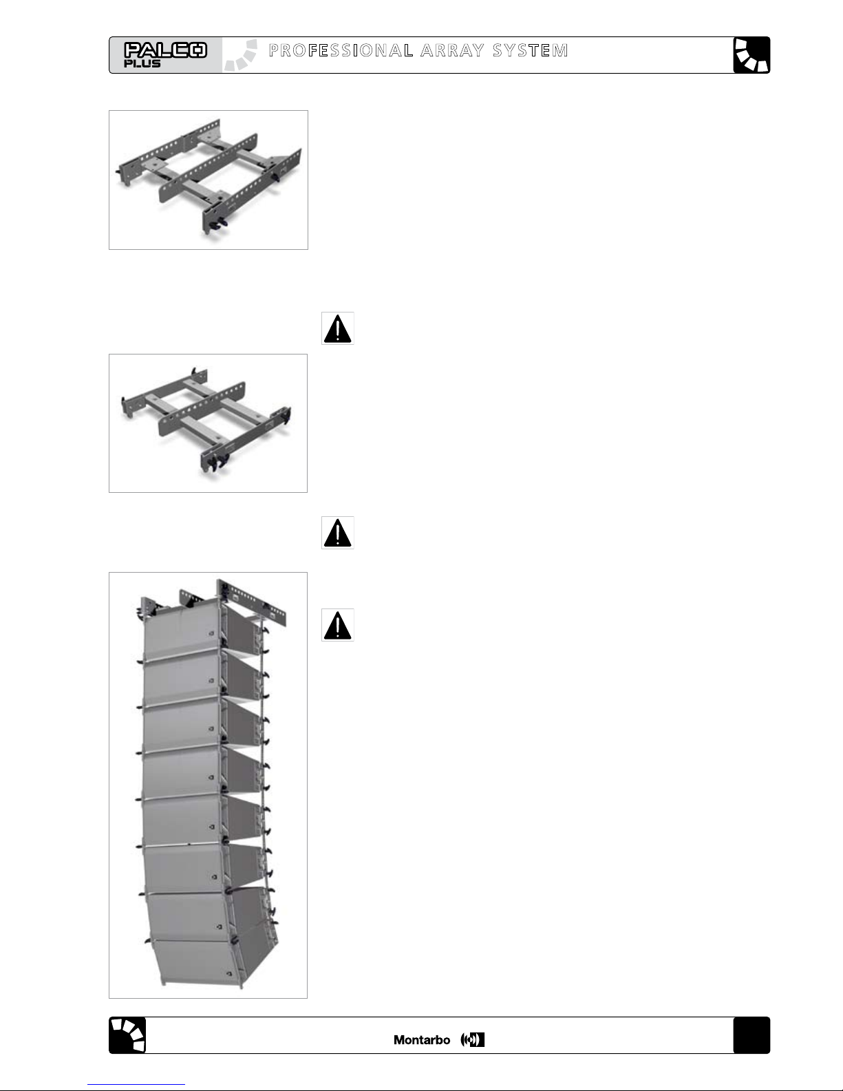
2.2 - BUMPER - model B1 (figure 9)
Suspension frame (grid) made of high-resistance steel, certified for flying
up to 16 RA16 units and that doubles as lower base for stacked installations
of up to 6 RA16 units on stage surface or on an RAB1815 unit.
If the BUMPER is stacked on an RAB1815, then the user must install suitable
anti-slip feet (not supplied), screwed into the M16 inserts incorporated in
the BUMPER. If the BUMPER is lpositioned on the ground or stage surface,
the use of the anti-slip feet is suggested, but not mandatory.
The BUMPER has several hoisting points, that will give different aiming
angles ("tilt" angles) when the system is flown.
The BUMPER is fitted with 4 fixing plates for 100 mm casters (not supplied).
It is supplied complete with 6 (3/8" x 1") quick release pins.
CAUTION: to fix the BUMPER, use the quick release pins supplied
with it exclusively. DO NOT use the pins supplied with the RA16
enclosures !!!
2.3 - BUMPER LIGHT - model B2 (figure 10)
Similar to model B1, but lighter. It is certified for flying up to 8 RA16 units
and doubles as a lower base for stacking on the ground or stage surface
a maximum of 4 RA16 units (after the mandatory installation of suitable
anti-slip feet, not supplied). It is supplied complete with 6 (3/8" x 1") quick
release pins.
CAUTION: to fix the BUMPER, use the quick release pins supplied
with it exclusively. DO NOT use the pins supplied with the RA16
enclosures !!!
CAUTION: in case of use of the BUMPER (mod. B1 or mod. B2) laid
on the ground or stage surface, the position of the center of mass
must be verified by means of the EASE Focus program.
Both B1 and B2 BUMPERS are supplied with front suspension plates, for
connecting them to the first speaker of the array. These plates are retained
in their transport position (protected) by two quick release pins.
These pins must be removed to rotate the plates into their operating
position (see chapter 4).
The EASE FOCUS software will suggest the optimal rigging point for the
desired result.
For the correct use of the BUMPERS, especially regarding maximum load
and rigging point, refer to chapters 3 and 4.
Figure 10. BUMPER LIGHT model B2
Figure 9. BUMPER - model B1
Figure 11. An array of 8 RA16
speakers flown from the BUMPER
english english
46
user’s manualuser’s manual
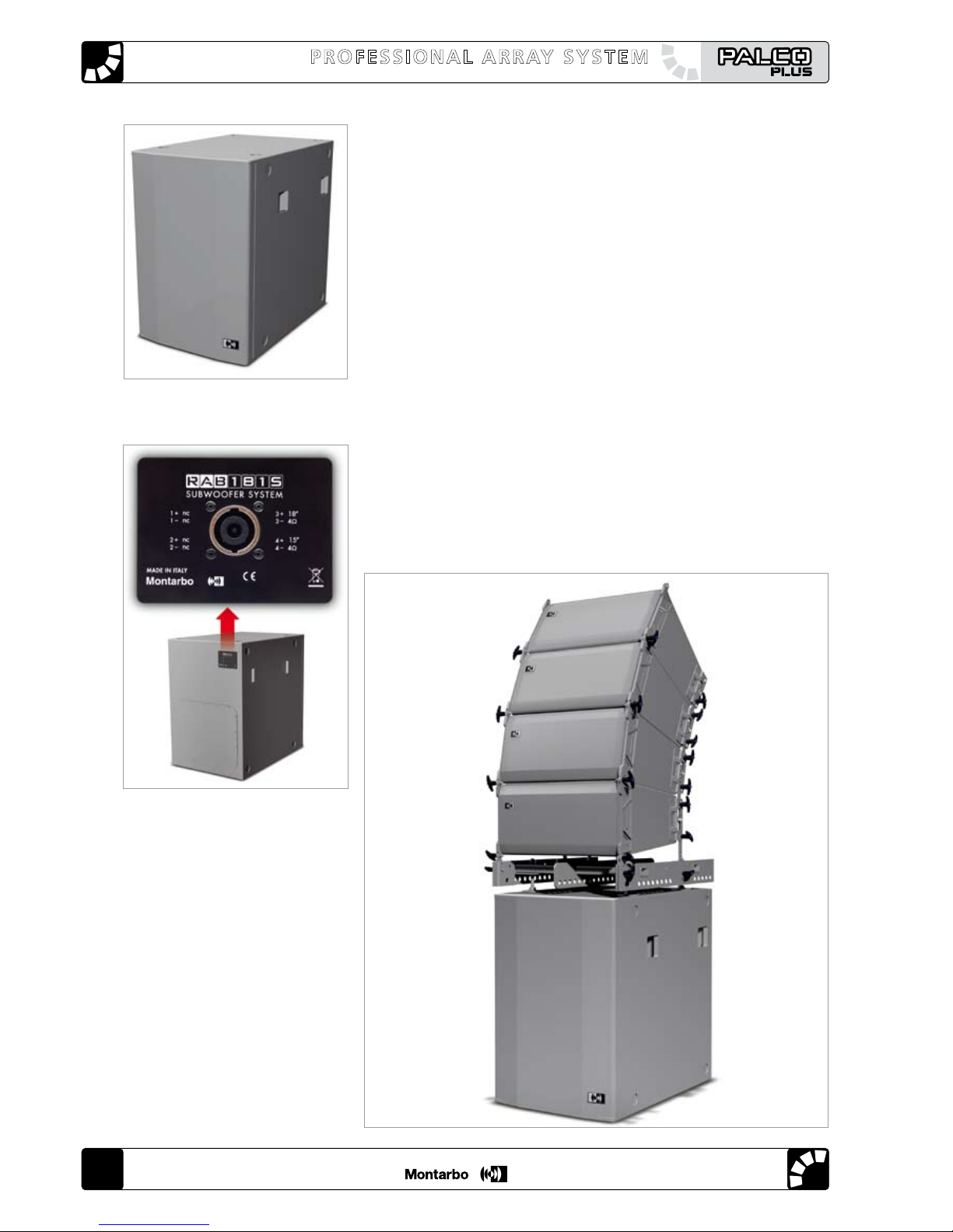
2.4 - RAB1815 - cardioid sub-bass unit (figure 12)
Cardioid sub-bass, designed to extend the low frequency range of the
PALCOPLUS system to 30 Hz.
It employs two low-frequency drivers: an 18-inch (bass-reflex-loaded)
and a 15-inch (horn-loaded), both featuring a 4-inch, long-excursion voice
coil, a dual-spider and a super-ventilated neodymium magnet.
The synergy between the drivers results in a "fast" and accurate bass
response. The drivers' different acoustic loads compensate their frequency
response and extend and correct the system’s response in the very low
range, thus increasing its throw and directivity.
The polar response is "cardioid" within a large band. A conventional
woofer has a response that is practically omni-directional. Instead RAB1815
has a "directive" response, meaning that the acoustic energy is directed
only where it is needed. The reduced emission from the enclosure's rear
helps attenuate the low frequency acoustic feedback on stage.
For each module a two channel power amplifier (2 x 1600 W / 4 ohm) is
specified; this amplifier is driven by the dedicated LM24 controller.
Connection to power amplifiers is by an 8-pole
n e u t r i k s p e a k o n
®
socket
(figure 13). For wiring details, refer to chapter 5.
One RAB1815 sub-bass unit may be used as a base for a ground or stage
level stacked array of RA16 speakers, installed on top of BUMPER model B1
(figure 14).
Figure 14. An array of 4 RA16
speakers stacked on a model
B1 BUMPER and an RAB1815
Figure 12. RAB1815
Figure 13. RAB1815 rear panel
user’s manualuser’s manual
user’s manualuser’s manual
47
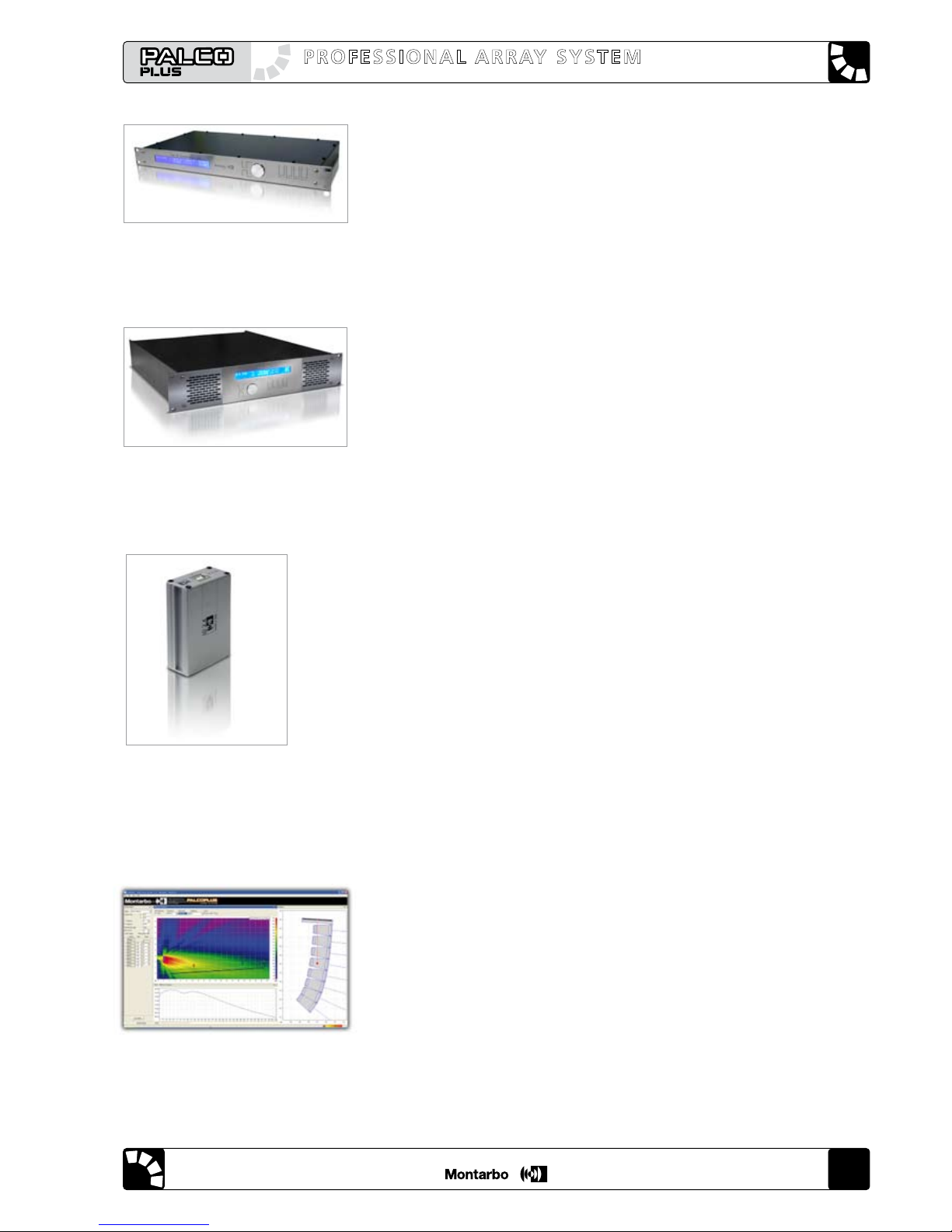
Figure 15. LM24
2.5 - LM24 - digital controller (figure 15)
Thanks to it’s "state-of-the-art" DSP and A/D and D/A converters, this unit
will drive the system’s power amplifiers; operating simultaneously
as a cross-over, equalizer and limiter to optimize the system's response.
It may be used in a free-standing mode, utilizing the front panel's LCD
display and keyboard to operate on factory pre-sets with adjustable
parameters; or it may be controlled by a personal computer that, thanks to
the RACon control software and the LD2.4 USB interface (figure 16), allows
adjustment and configuration of a network of up to 8 LM24 controllers.
For wiring instruction, refer to chapter 5.
For detailed instructions about the LM24 and the RACon PC software, refer
to the LM24 user's manual.
2.6 - PLM6800 'powered controller' 4-channel power amplifier with digital
loudspeaker management (figure 15 b)
Model PLM6800 is a "powered loudspeaker controller" designed to
be used with the PalcoPlus line-array system. It incorporates a digital
controller (functionally equivalent to the model LM24) and four power
amplifiers, each one capable of delivering up to 1700 W @ 4 ohms.
A single PLM6800 may effortless drive one PALCOPLUS system composed by
two RA16 speakers and one RAB1815 woofer. The system's wiring is made
easy thanks to an 'intelligent' control of the power amps output wiring,
offering a real protection of the system's drivers against wiring errors.
The PLM6800 may be used in free-standing mode by means of the front
panel's LCD display and keyboard, operating on factory pre-sets with
adjustable parameters, or it may be controlled by a personal computer
that, thanks to the RACON control software and the LD2.4 USB interface,
allows adjustment and configuration of a network of up to eight PLM6800.
2.7 - EASE Focus - Aiming Software (figure 17)
Dedicated acoustical simulation software: starting from a geometric model
of the actual venue space (geometry of the place, audience position,
number of speakers to be used), it will compute, in an interactive mode,
the array's geometry, calculating the splay angles to be assigned to the
array modules during the array assembly.
It will also indicate the exact position of the hoisting point on the BUMPER,
so that the array will have the correct tilt angle once flown.
For instructions about the software’s installation, refer to chapter 9.
The program includes a complete and detailed on-line help, and we
suggest that the user refer to it for more details.
Figura 15b: PLM6800
Figura 16. USB LD2.4 interface
Figure 17. EASE Focus screen
shot

english english
48
user’s manualuser’s manual
3. RIGGING THE SYSTEM
This chapter contains important information about flying a PALCOPLUS
line array system, as well as a description of the elements and safety
precautions.
Our goal is to allow the user to become familiar with the procedures
to be followed while flying the acoustic system, as well as the safety
measures to be taken during set-up and disassembly.
Before performing any operations related to flying the system, read the
present chapter first, and heed the warnings and advice given.
Only experienced persons with the required knowledge of the equipment
and local safety regulations should fly speaker systems.
It is the user’s responsibility to ensure that the systems to be flown
(including flying accessories such as structures, hoists, chains and cables)
comply with applicable government and local regulations.
The working load limits stated in this manual have been certified by
independent laboratories.
It is the user’s responsibility to comply with loads limits, safety factors,
resistance values, periodical checks and all the warnings given in this
manual.
The suspension accessories supplied by Montarbo are suitable for rigging:
• up to 8 RA16 speakers with a B2 BUMPER
• up to 8 RA16 speakers with a B1 BUMPER, when using a single suspension
point
• up to 16 RA16 speakers with a B1 BUMPER, when using two suspension
points.
The loading capacity of the suspension accessories supplied by Montarbo
have been certified by an external structural design consultant.
A partial copy of the certification document is enclosed in the appendix.
The compete document, in it's original form, is available at the Montarbo
main offices.
user’s manualuser’s manual
user’s manualuser’s manual
49
3.1 - SAFETY STANDARDS AND REGULATIONS
To this date and to our knowledge, there is no accepted standard or
regulation regarding the flying of acoustic systems.
However, it is common engineering practice to apply 5:1 safety factors
for enclosures and static elements.
For slings and elements exposed to material fatigue due to friction and
load variation, the following ratios must be met:
5:1 for steel cable slings,
4:1 for steel chain slings and
7:1 polyester slings (not allowed in some countries)
Thus, an element such a steel chain, with a breaking load limit of 1000 Kg
may be statically loaded with 250 Kg (4:1 safety factor).
When flying a system, the working load must be lower than the resistance
of each individual flying point in the array, as well as on each enclosure.
3.2 - SAFETY CHECKS AND INSPECTIONS
Hanging hardware should be regularly inspected and suspect units
replaced if there is any doubt.
This is important to avoid injury and damage, and absolutely no risks
should be taken in this respect.
We strongly recommend that an inspection and maintenance program
on flying elements be implemented.
This should be done in a written form and include reports filled out by
the personnel that will carry out the inspections.
In case of accident, local regulations may require you to present evidence
of inspection reports and corrective actions taken after defects were found.
Regulation on hoist and chain maintenance in some countries require
a programmed inspection and maintenance program to be performed by
a Certified Body or by a competent professional.
No risks should be taken with regards to public safety. Absolutely!
When flying enclosures from ceiling support structures, extreme care
should be taken to assure, by calculation and in some cases by actual
measurement, that the load-bearing capabilities of the structures are
not exceeded, so that the installation is absolutely safe.
Do not fly enclosures from unsafe structures. Consult a certified
professional if needed.
All ying accessories that are NOT supplied by Montarbo are the user’s
responsibility. Use at your own risk.
english english
50
user’s manualuser’s manual
4 - SETTING uP AND ASSEMBLING THE ARRAY
The mechanical set-up of the array is carried out in two phases:
a) assembly of the RA16 speakers and the BUMPER, using the rear rigging
plates (that allow joining the speakers composing the array and adjusting
the splay angle between adjacent speakers) and the quick-release pins,
featuring a ball safety lock (QuickLock).
b) "flying" the system or positioning it on the ground or stage floor.
To simplify the operation, the two phases may be carried out
simultaneously.
The suspension accessories supplied by Montarbo are suitable for rigging:
• up to 8 RA16 speakers with a B2 BUMPER
• up to 8 RA16 speakers with a B1 BUMPER, when using a single suspension
point
• up to 16 RA16 speakers with a B1 BUMPER, when using two suspension
points.
Before beginning the assembly work, the array geometry (the splay angles
between the different RA16 enclosures) must be determined using the
EASE Focus software program, then the following operations must be
carried out:
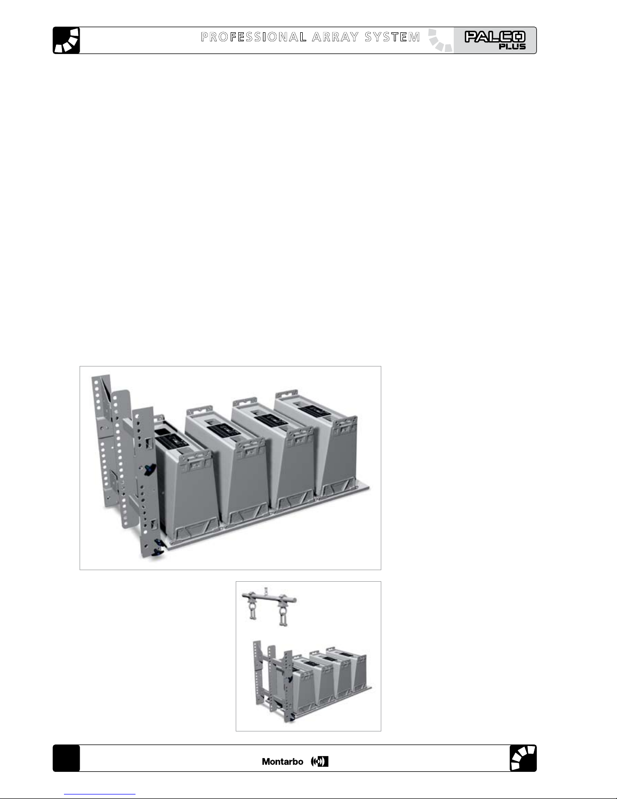
Figure 18.1
Figure 18.2
1) Align on the floor or on a
horizontal plane (e.g. a wooden
board of suitable size and strength)
all the RA16 speakers and the
BUMPER (figure 18.1).
Make sure that their orientation
is correct (top-bottom).
2) Make sure that the BUMPER is
placed under the support structure's
rigging point (figure 18.2).
user’s manualuser’s manual
user’s manualuser’s manual
51
Figure 18.3
Figure 18.4
Figure 18.5
3) Join all the speakers, using only
the front plate holes, using two pins
per speaker (figure 18.3).
4) Remove the two pins that retain the front plates of the BUMPER in the
transport position. Rotate the plates into the working position (horizontal)
and fasten them with the two pins removed before (figure 18.4).
5) Join the front plate of the first
speaker and the front side of
the BUMPER, using the front plates
of the BUMPER and two pins
(figure 18.5).
CAUTION: to fix the
BUMPER, use the quick
release pins supplied with
it exclusively.
DO NOT use the pins supplied with
the RA16 enclosures !!!
 Loading...