

Montarbo GRAVIS, GRAVIS 24, GRAVIS 30, GRAVIS 46, GRAVIS 62 User Manual
Professional Power Amplifier
User s Manual'
English
GRAVIS SERIES
GR AVIS 24
PROT
CLIP
-5dB
-10dB
SIG
BRG
PAR
ON
-80
0
-1
-3
-5
-6
-8
-10
-20
dB
CH1
0
-1
-3
-5
-6
-8
-10
-20
dB
CH2

1
CONTENTS
Important precautions........................................................................................................................2
GRAVIS series front panel and function description............................................................................3
GRAVIS series rear panel and function description.............................................................................4
GRAVIS series connections set up ....................................................................................................5
Protection circuits .............................................................................................................................7
Ex-factory settings ............................................................................................................................7
Use environment ..............................................................................................................................7
Applications .....................................................................................................................................7
Block diagram...................................................................................................................................8
Specifications ...................................................................................................................................9
GRAVIS series dimensions .............................................................................................................10

2
IMPORTANT PRECAUTIONS
1.Read all documentation before operating your equipment.
2.Retain all documentation for further reference.
3.Mains voltage must correspond to rear unit label.
4.Damages caused by connecting to improper AC voltage are not covered by any warranty.
5.Always operate the unit with the AC ground wire connected to the electrical system ground.
Precautions should be taken to avoid equipment faulty, improper or inefficient grounding.
6.After connection to power supply Standby LED is lit, showing that some components inside are
already powered.
7.Do not connect any amplifier channel output into another channel input. Do not connect in parallel or
series an amplifier output with any other amplifier output.
8.In system setup, amplifier's output power should be 50% greater than loudspeaker(s) rated handling
power.
9.Make sure the signal is correctly connected to amplifier input channel following current input mode.
10.Please turn off the power switch when extracting the power cord and signal cable, or adjusting the
input mode switch.
11.In order to split one signal to more than one amplifier, we suggest to use a signal distributor.
12.In typical use, please set the volume to -0dB position.
13.If you need to supply power to more than one unit power amplifiers,to eliminate the big surge current
interference to electricity net, and preventing the voltage fluctuate abnormal when simultaneously
switching on the amplifiers, we recommend you use the sequence power procedure.
14.Do not obstruct the air entrance and exit ports.
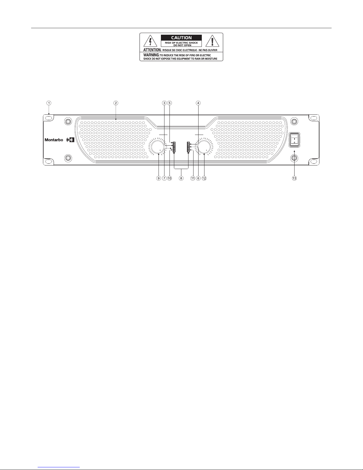
GRAVIS series front panel function description:
Important: Control functions and adjustment functions not described in this user's manual may cause
mechanical danger or electrical shock.
3
GRAVI S 62
ON
OFF
CH2CH1
PROT
CLIP
-5dB
-10dB
SIG
BRG PAR
ON
-10
0
-1
-3
-5
-6
-8
-20
-80
dB
0
-1
-3
-5
-6
-8
-20
-80
dB
1. Installation socket
To be used to fix in 19" rack installation.
2. Air entrance
This is the air entrance, don't block it. Since the dust will settle in the grille, please regularly remove
the screws to clean the filter under the grille, thus maintaining a good ventilation.
3. -5dB signal indicator LED
When signal is at -5dB, this orange LED will be lit.
4. CLIP indicator
When this indicator is on, it means the amplifier has distortion (CLIP). In this status, the distortion is
around 0.5%.
5. Protection Indicator
When this indicator is lit, it means the amplifier is in protection status, which should be due to output
short-circuit, over-heat,DC, VHF (constant non-musical high frequency signal due to self-excitation
or long time high-frequencies feedback).
6. -10 dB signal indicator LED
This green LED will be lit when signal at -10dB.
7. Signal indicator
With signal is up to -22dB, the green indicator LED will be lit. This LED is on with an input level
around 0.35V.
8. Power ON Indicator
When this indicator is on, it means the main power supply system of amplifier is working.
9. CH1 volume control
In stereo or parallel mode: this knob controls CH1 volume. In bridge mode, this knob controls both
channels volume, while CH2 knob is disabled.
Gain control range: -80dB~0dB in 40 steps, available turning angle is 280 degree.
10.Bridge indicator
When this indicator is lit the amplifier is on bridge mode, as set by rear panel dip switches.
11.Parallel indicator
When this indicator is lit the amplifier is on parallel mode, as set by rear panel dip switches.
12.CH2 volume control
In stereo or parallel mode, this knob controls CH2 volume. In bridge mode, this knob is inactive, the
amplifier volume is controlled by CH1 knob only.
Gain control range: -80dB~0dB in 40 steps, available turning angle is 280 degree.
13.Power Switch
This switch is used to turn power on and off. Press the upper part to switch ON, and lower part to
switch OFF.
 Loading...