

Montarbo 716 S Instruction Manual
stereo powered mixer
stereo powered mixer
71 71
6 S S
71
71
6 S
S
stereo powered mixer
stereo powered mixer
ENGLISH
FRANÇAIS
5 - 10
11 - 16
APPENDIX
specifications
block diagram
connections
example of connection
17 - 23
1
1
LINE
MIC.
LINE
MIC.
LINE
MIC.
LINE
MIC.
LINE
MIC.
LINE
MIC.
LINE
MIC.
LINE
MIC.
2 3 4 5 6 7 8
2 3 4 5 6 7
PHANTOM 48V.
15/169/10 11/12 13/14
LINE
MIC.
LINE
8
R
LINE
L
(mono)
R
L
(mono)
LINE
R
L
(mono)
LINE
R
L
(mono)
E 1
40
30
18
6
0
6
+
40
30
18
6
0
6
+
40
30
18
6
0
6
+
E 2
BAL
L
R
BAL
L
R
ON
5
0
4
1
3
28
9
10
7
6
A
5
0
4
1
3
28
9
10
7
6
B
5
0
4
1
3
28
9
10
7
6
A
5
0
4
1
3
28
9
10
7
6
tone tone
PROGRAM PROGRAM
3
+
0dB
3
10
20
3
+
0dB
3
10
20
5
0
4
1
3
28
9
10
7
6
5
0
4
1
3
28
9
10
7
6
INPUT LEVEL INPUT LEVEL
2
1
effect 1 effect 2
ON
ABL R
L.F.
0
15
2
12
4
88
12
15
4
2
-
+
L.F.
0
15
2
12
4
88
12
15
4
2
-
+
BAL
L
R
BAL
L
R
5
0
4
1
3
28
9
10
7
6
5
0
4
1
3
28
9
10
7
6
5
0
4
1
3
28
9
10
7
6
5
0
4
1
3
28
9
10
7
6
5
0
4
1
3
28
9
10
7
6
5
0
4
1
3
28
9
10
7
6
B
BB
AA
GAIN GAIN
L.M.
0
15
2
12
4
88
12
15
4
2
-
+
L.M.
0
15
2
12
4
88
12
15
4
2
-
+
H.M.
0
15
2
12
4
88
12
15
4
2
-
+
H.M.
0
15
2
12
4
88
12
15
4
2
-
+
H.F.
0
15
2
12
4
88
12
15
4
2
-
+
H.F.
0
15
2
12
4
88
12
15
4
2
-
+
40
30
18
6
0
6
+
40
30
18
6
0
6
+
40
30
18
6
0
6
+
40
30
18
6
0
6
+
5
0
4
1
3
28
9
10
7
6
TAPE
IN
5
0
4
1
3
28
9
10
7
6
MONO
EQ
FLAT
5
0
4
1
3
28
9
10
7
6
PHONES
PHONES OUT
200 600
TAPE
OUT
LL
RR
IN
12AB RL
RETURNS MONITORS MASTER
flat
5
4
1
3
28
9
7
6
flat
5
4
1
3
28
9
7
6
EFF. 2
MONITORSAB
1
2
L R/(MONO)
PHANTOM
48 V DC
EFF. 1
EFF.SEND 1STEREO EFF. RET.
MONO OUT
EFF.SEND 2
INSERTLR
MUTE
MUTE
ON
ON
2 x 350W Stereo Powered Mixer
&
2 x160 - Programs
Montarbo Digital Effects Processor
MontarboMontarbo
716 S716 S
Hz
3131 6363 125125 250250 500500 1K1K 2K2K 4K4K 8K8K 16K16K
Hz
STEREO EFFECTS
40
30
18
6
0
6
+
PAN
2
peak
5
0
4
1
3
28
9
10
7
6
5
0
4
1
3
28
9
10
7
6
L
R
M
B
5
0
4
1
3
28
9
10
7
6
A
5
0
4
1
3
28
9
10
7
6
L.F.
0
15
2
12
4
88
12
15
4
2
GAIN
H.F.
FREQ.
1.3
.18
.3 2
3 KHz
.75 1.6
LEVEL
MID.
0
15
2
12
4
88
12
15
4
2
dB
5
4
1
3
28
9
10
7
6
0
15
2
12
4
88
12
15
4
2
-
+
-
+
-
+
1
40
30
18
6
0
6
+
PAN
2
peak
5
0
4
1
3
28
9
10
7
6
5
0
4
1
3
28
9
10
7
6
L
R
M
B
5
0
4
1
3
28
9
10
7
6
A
5
0
4
1
3
28
9
10
7
6
L.F.
0
15
2
12
4
88
12
15
4
2
GAIN
H.F.
FREQ.
1.3
.18
.3 2
3 KHz
.75 1.6
LEVEL
MID.
0
15
2
12
4
88
12
15
4
2
dB
5
4
1
3
28
9
10
7
6
0
15
2
12
4
88
12
15
4
2
-
+
-
+
-
+
1
40
30
18
6
0
6
+
PAN
2
peak
5
0
4
1
3
28
9
10
7
6
5
0
4
1
3
28
9
10
7
6
L
R
M
B
5
0
4
1
3
28
9
10
7
6
A
5
0
4
1
3
28
9
10
7
6
L.F.
0
15
2
12
4
88
12
15
4
2
GAIN
H.F.
FREQ.
1.3
.18
.3 2
3 KHz
.75 1.6
LEVEL
MID.
0
15
2
12
4
88
12
15
4
2
dB
5
4
1
3
28
9
10
7
6
0
15
2
12
4
88
12
15
4
2
-
+
-
+
-
+
1
40
30
18
6
0
6
+
PAN
2
peak
5
0
4
1
3
28
9
10
7
6
5
0
4
1
3
28
9
10
7
6
L
R
M
B
5
0
4
1
3
28
9
10
7
6
A
5
0
4
1
3
28
9
10
7
6
L.F.
0
15
2
12
4
88
12
15
4
2
GAIN
H.F.
FREQ.
1.3
.18
.3 2
3 KHz
.75 1.6
LEVEL
MID.
0
15
2
12
4
88
12
15
4
2
dB
5
4
1
3
28
9
10
7
6
0
15
2
12
4
88
12
15
4
2
-
+
-
+
-
+
1
40
30
18
6
0
6
+
PAN
2
peak
5
0
4
1
3
28
9
10
7
6
5
0
4
1
3
28
9
10
7
6
L
R
M
B
5
0
4
1
3
28
9
10
7
6
A
5
0
4
1
3
28
9
10
7
6
L.F.
0
15
2
12
4
88
12
15
4
2
GAIN
H.F.
FREQ.
1.3
.18
.3 2
3 KHz
.75 1.6
LEVEL
MID.
0
15
2
12
4
88
12
15
4
2
dB
5
4
1
3
28
9
10
7
6
0
15
2
12
4
88
12
15
4
2
-
+
-
+
-
+
1
40
30
18
6
0
6
+
PAN
2
peak
5
0
4
1
3
28
9
10
7
6
5
0
4
1
3
28
9
10
7
6
L
R
M
B
5
0
4
1
3
28
9
10
7
6
A
5
0
4
1
3
28
9
10
7
6
L.F.
0
15
2
12
4
88
12
15
4
2
GAIN
H.F.
FREQ.
1.3
.18
.3 2
3 KHz
.75 1.6
LEVEL
MID.
0
15
2
12
4
88
12
15
4
2
dB
5
4
1
3
28
9
10
7
6
0
15
2
12
4
88
12
15
4
2
-
+
-
+
-
+
1
40
30
18
6
0
6
+
PAN
2
peak
5
0
4
1
3
28
9
10
7
6
5
0
4
1
3
28
9
10
7
6
L
R
M
B
5
0
4
1
3
28
9
10
7
6
A
5
0
4
1
3
28
9
10
7
6
L.F.
0
15
2
12
4
88
12
15
4
2
GAIN
H.F.
FREQ.
1.3
.18
.3 2
3 KHz
.75 1.6
LEVEL
MID.
0
15
2
12
4
88
12
15
4
2
dB
5
4
1
3
28
9
10
7
6
0
15
2
12
4
88
12
15
4
2
-
+
-
+
-
+
1
40
30
18
6
0
6
+
PAN
2
peak
5
0
4
1
3
28
9
10
7
6
5
0
4
1
3
28
9
10
7
6
L
R
M
B
5
0
4
1
3
28
9
10
7
6
A
5
0
4
1
3
28
9
10
7
6
L.F.
0
15
2
12
4
88
12
15
4
2
GAIN
H.F.
FREQ.
1.3
.18
.3 2
3 KHz
.75 1.6
LEVEL
MID.
0
15
2
12
4
88
12
15
4
2
dB
5
4
1
3
28
9
10
7
6
0
15
2
12
4
88
12
15
4
2
-
+
-
+
-
+
1
STEREO DIGITAL
EFFECTS PROCESSOR
EXTERNAL
EFFECTS SEND
STEREO
EXTERNAL
EFFECTS
40
30
18
6
0
6
+
BAL
2
peak
5
0
4
1
3
28
9
10
7
6
5
0
4
1
3
28
9
10
7
6
B
5
0
4
1
3
28
9
10
7
6
A
5
0
4
1
3
28
9
10
7
6
0
15
2
12
4
88
12
15
4
2
GAIN
H.F.
5
4
1
3
28
9
10
7
6
0
15
2
12
4
88
12
15
4
2
-
+
-
+
1
M.F.
0
15
2
12
4
88
12
15
4
2
-
+
L.F.
L
R
40
30
18
6
0
6
+
BAL
2
peak
5
0
4
1
3
28
9
10
7
6
5
0
4
1
3
28
9
10
7
6
B
5
0
4
1
3
28
9
10
7
6
A
5
0
4
1
3
28
9
10
7
6
0
15
2
12
4
88
12
15
4
2
GAIN
H.F.
5
4
1
3
28
9
10
7
6
0
15
2
12
4
88
12
15
4
2
-
+
-
+
1
M.F.
0
15
2
12
4
88
12
15
4
2
-
+
L.F.
L
R
40
30
18
6
0
6
+
BAL
2
peak
5
0
4
1
3
28
9
10
7
6
5
0
4
1
3
28
9
10
7
6
B
5
0
4
1
3
28
9
10
7
6
A
5
0
4
1
3
28
9
10
7
6
0
15
2
12
4
88
12
15
4
2
GAIN
H.F.
5
4
1
3
28
9
10
7
6
0
15
2
12
4
88
12
15
4
2
-
+
-
+
1
M.F.
0
15
2
12
4
88
12
15
4
2
-
+
L.F.
L
R
40
30
18
6
0
6
+
BAL
2
peak
5
0
4
1
3
28
9
10
7
6
5
0
4
1
3
28
9
10
7
6
B
5
0
4
1
3
28
9
10
7
6
A
5
0
4
1
3
28
9
10
7
6
0
15
2
12
4
88
12
15
4
2
GAIN
H.F.
5
4
1
3
28
9
10
7
6
0
15
2
12
4
88
12
15
4
2
-
+
-
+
1
M.F.
0
15
2
12
4
88
12
15
4
2
-
+
L.F.
L
R
XLR IN
pin 1 - GND
pin 2 pin 3 -
9/10 11/12 13/14 15/16
0
3
6
9
12
3
6
9
12
dB 0
3
6
9
12
3
6
9
12
dB
0dB
3
6
9
3
6
9
12
15
18
0
3
6
9
3
6
9
12
15
18
dB0
3
6
9
3
6
9
12
15
18
peak peak
3
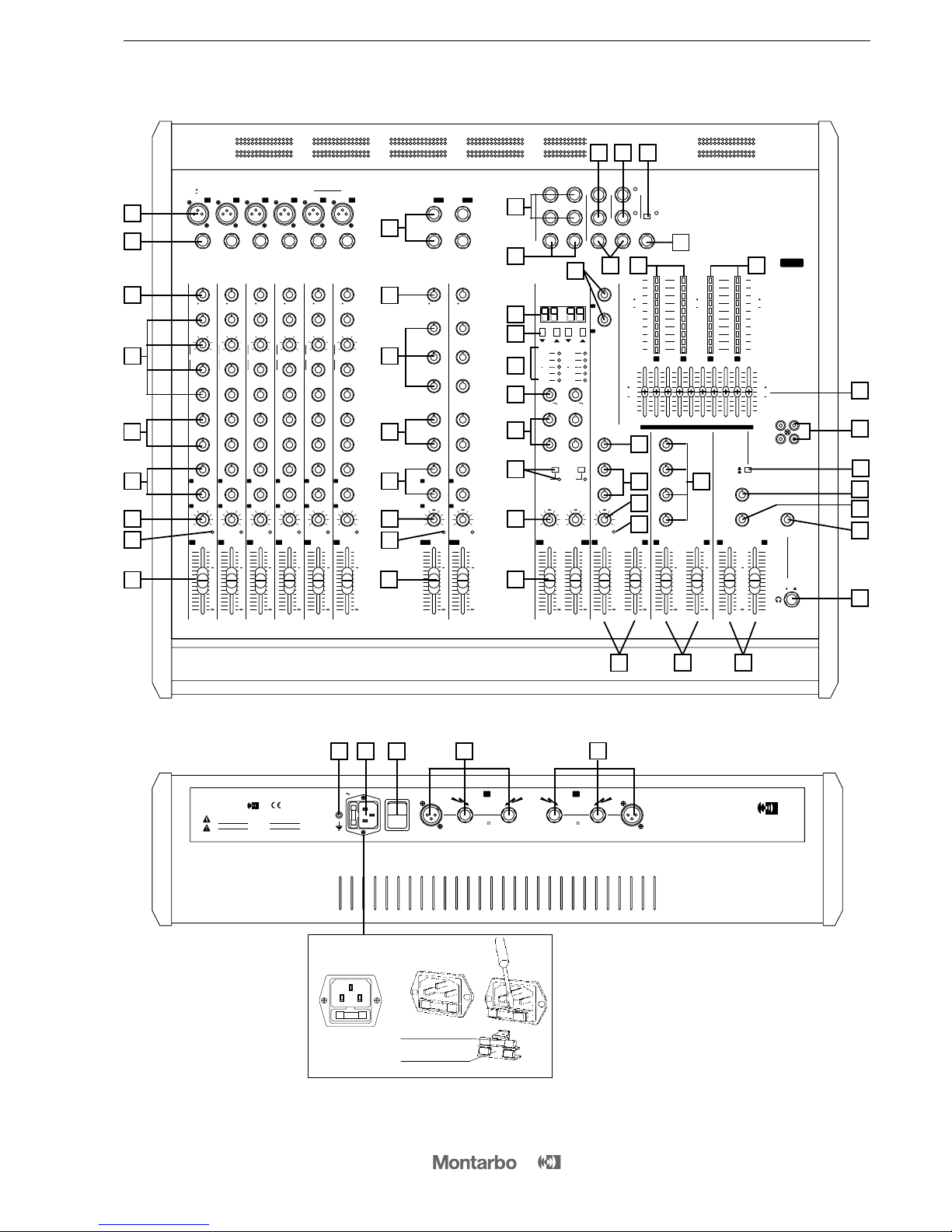
FRONT and REAR PANELS
9
10
1
2
3
4
5
6
7
18
11
12
13
14
16
15
17
22
26
25
24
23
21
19
20
35
47
8
34 27
49
50
39
36
51
41
42
44
43
45
52
40
37
28
30
29
220V-240V
50 60Hz
FUSE
F 6,3A
POWER
I
O
350 W
L R
350 W
( min. load )
4
( min. load )
4
OUTPUTS
Pin 1 Pin 2 Pin 3 -
GND
signal
n.c.
Pin 1 Pin 2 Pin 3 -
GND
signal
n.c.
Montarbo
2 x 350W STEREO POWERED MIXER
MOD.
716S
MANUFACTURED AND MADE IN ITALY BY
Montarbo
Montarbo
ELETTRONICA
s.r.l.
TO PREVENT RISK OF FIRE ALWAYS REPLACE
FUSES WITH SAME TYPE AND RATINGS
THIS APPARATUS MUST BE EARTHED
CAUTION !
TO PREVENT ELECTRICAL SHOCK,
DO NOT REMOVE COVERS
CET APPAREIL DOIT ETRE RELIE A LA TERRE
POUR PREVENIR TOUT RISQUE DE FEU REPLACER
TOUJOURS UN FUSIBLE DE MEME CARACTERISTIQUES
AVIS !
POUR PREVENIR TOUT RISQUE DE CHOC
ELECTRIQUE, NE PAS OUVRIR
`
^
^
48 48 53 46 54
32
31
33
38
service fuse
reserve fuse
I.E.C. power supply socket:
fuse replacement
71
71
6 S
S
4
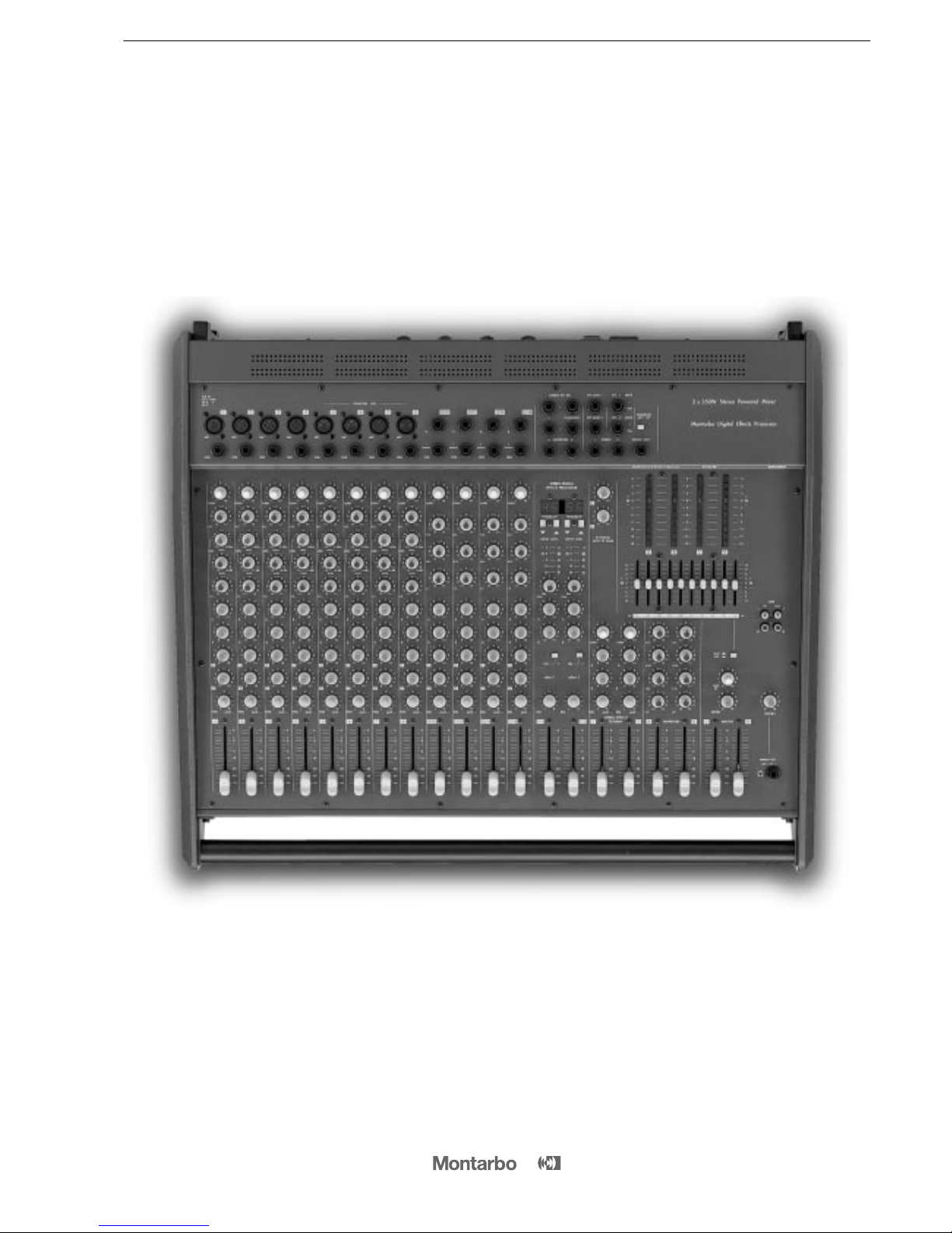
stereo powered mixer
stereo powered mixer
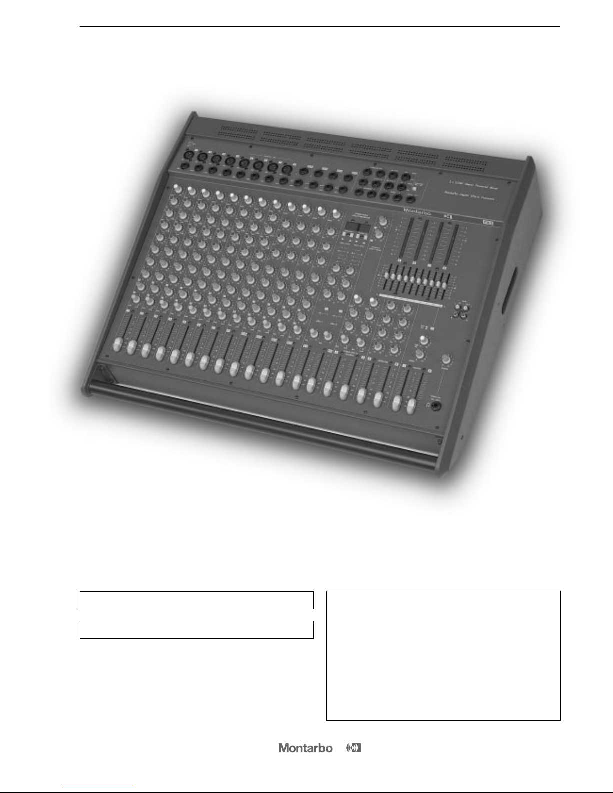
The powered mixer 716S is compact and easy to install and
operate everywhere, it can be hooked up to your system in
a breeze.
La table de mixage amplifié 716S est synonyme de rationalité et de
rendement.
Caractérisé par une riche dotation de commandes et une grande
puissance de sortie, 716S réunisse la qualité sonore et la fiabilité
dans un système compact qui garantit les meilleures performances
de la plus grande facilité d'utilisation.
__________________________________________
__________________________________________
__________________________________________
__________________________________________
__________________________________________
__________________________________________
__________________________________________
__________________________________________
__________________________________________
__________________________________________
__________________________________________
__________________________________________
CONTENTS
Front and rear panels
Introduction
Controls and connections
Important !
Stereo graphic equalizer
Dual stereo multieffect DSP
Appendix:
◗ Technical specifications
◗
Block diagrams
◗
Connections
◗
Connection example
3
4
6 - 8
9
9
10
17 - 23
18
19
20 - 22
23
ENGLISH
71
71
6 S
S
stereo powered mixer
stereo powered mixer
WARNING !
In order to protect your own and others' safety and to avoid
invalidation of the warranty of this product, please read this
section carefully before operating this product.
- This product has been designed and manufactured for being operated as
powered mixing console in the applications tipical of a sound reinforcement system
or of a sound recording system. Operation for purposes and
in applications
other than these has not been covered by the manufacturer
in the design of the product, and is therefore to be undertaken at end
user's and/or installer's sole risk and responsability.
To avoid the risk of fire and/or electric shock:
• Never expose this product to rain or moisture, never use it in proximity of
water or on a wet surface. Never let any liquid, as well as any object, enter
the product. In case, immediately disconnect it from the mains supply and
refer to servicing before operating it again.
• Before connecting this product to the mains supply, always make sure
that the voltage on the mains outlet corresponds to that stated on the
product.
• This product must be connected only to a grounded mains outlet
complying to the safety regulations in force via the supplied power cable.
In case the power cable needs to be substituted, use exclusively a cable of
the same type and characteristics.
• Never place any object on the power cable. Never lay the power cable
on a walkway where one could trip over it. Never press or pinch it.
• Never install the product without providing adequate airflow to cool it.
Never obstruct the air intake openings on it.
• In case the external fuse needs replacement, substitute it only with one
of the same type and rating, as stated on the product.
• Always make sure the On/Off switch is in its 'Off' position before doing
any operation on the connections of the product.
• Before attempting to move the product after it has been installed,
remove all the connections.
• To disconnect the power cable of this product from the mains supply
never pull the cable directly instead, hold the body of the plug firmly and
pull it gently from the mains supply outlet.
- Before placing the product on a surface of any kind, always make sure
that its shape and load rating will safely match the product's size and
weight.
-
To avoid shocks always reserve a protected area with no access to unqualified
personnel as installation site of the product. In case the product is used near
children and animals closest supervision is necessary.
- This product in combination with headphones or speakers can generate
very high acoustic pressures which are dangerous for the hearing system.
Do not operate for a long period of time at a high or unconfortable volume
level. Never expose children to high sound sources.
CAUTION !
This product does not contain user serviceable parts.
To prevent fire and/or electrical shock, never remove its cover.
Maintenance and servicing must be carried out only by
Elettronica Montarbo srl or the official Montarbo Distributor
in your State or by qualified personnel specifically authorized
by them.
5
IMPORTANT ! Safety instructions
The lighting flash with arrowhead symbol within an equilateral triangle, is intended
to alert the user to the presence of uninsulated "dangerous voltage" within the
product's enclosure, that may be of sufficient magnitude to constitute a risk of
electric shock to humans.
The exclamation point within an equilateral triangle, is intended to alert the user
to the presence of important operating and maintenance (servicing) instructions.

6
CONTROLS AND CONNECTIONS
MONO INPUT CHANNEL
1 ➤ GAIN: adjust the gain (sensitivity) of the line and mic inputs,
allowing connections of signal sources (both line and mic level)
having a wide range of signal level. As a practical rule, the GAIN
control must be set to the maximum allowable level that will not
activate the peak level indicator. This will maximize the signal to
noise ratio.
2 ➤ H.F / MID FREQ. / MID LEVEL / L.F: 3-band equalizer with
parametric control of the mid range. While the High and Low
controls act on fixed frequency cuts, the Mid control allows to
choose the frequency to be lowered or raised.
H.F: adjusts the amount of boost or cut in the high frequency
range. Turning the control clockwise increases the amount of high
frequencies, counter-clockwise decreases it.
MID FREQ.: chooses the frequency to be lowered or raised.
MID LEVEL: adjusts the amount of boost or cut in the frequency
choosen by means of the MID FREQ. control.
Note: If the MID LEVEL control is set at '0' (centre) there will be no alteration in
the mid frequency band (independently of the MID FREQ. control setting).
L.F: adjusts the amount of boost or cut in the low frequency range.
Turning the control clockwise increases the amount of low frequencies, counter-clockwise decreases it.
3 ➤ A / B: monitor sends volumes (pre fader, post tone controls).
They set the level of that input channel in the monitor outputs.
4 ➤ 1 / 2: effect sends volumes (post fader and post tone controls).
They adjust the quantity of channel signal that is sent
both to the
correspondent built-in effect and to an external effect connected
to the 'EFF SEND 1/2' and to the 'STEREO EFF. RET. 1/2' sockets.
Note: On the channels where you don't want to have neither the internal effect
nor the external effect, turn these knobs fully anticlockwise.
Should the external effect only be required, then turn off the internal effect.
5 ➤ PAN: this control allows to place the channel’s input signal
within the stereo image by assigning more or less of the signal
to the left or right master volume controls.
6 ➤ PEAK: peak LED indicator. It lights when the signal level is
approaching the maximum (clipping) allowable level. The signal
is sampled in two points of the channel's signal path: • after the
input amplifier (micro and line); • after the equalizer.
If the LED is continuously lighted, you must reduce the input GAIN
or modify the equalizer settings, reducing the boost introduced by
the level controls HF, MID LEVEL and LF.
7 ➤ Channel VOLUME fader.
8 ➤ PHANTOM 48V DC: pushbutton for on/off switching of the
48V phantom power supply on the channels 5, 6, 7, 8 (the phantom
power supply allows use of condenser microphones).
Note: Before pushing this button, make sure that the unit is turned off or that
all the slider controls are to their lowest settings.
●
connections:
9 ➤ MIC: balanced XLR microphone input (for microphones).
10 ➤ LINE: unbalanced jack line input (for instruments and high
level sources).
Note: Do not use both the MIC and the LINE input of one channel at the
same time).
Do not connect instruments or other high level sources to the MICRO inputs
(this will result in distortion due to excessive signal level).
Do not connect microphones to the LINE inputs (the resulting signal will be
of low level and low quality) .
STEREO INPUT CHANNEL
11 ➤ GAIN: same as in the mono channel.
12 ➤ H.F / M.F / L.F.: 3-band equalizer.
H.F: adjusts the amount of high frequencies giving up to 15dB of
boost or cut at 15kHz.
M.F: adjusts the amount of mid frequencies giving up to 15dB of
boost or cut at 600Hz.
L.F: adjusts the amount of low frequencies giving up to 15dB of
boost or cut at 50Hz.
Note: Turning the control clockwise increases the amount of high, mid or low
frequencies, counter-clockwise decreases it. The reaponse is flat at the center
position.
13 ➤ A / B: same as in the mono channel.
14 ➤ 1 / 2: same as in the mono channel.
15 ➤ BAL: stereo balance. Allows to adjust the level of the input
signal in the left or right master outputs. If the channel is used as
a mono channel it becomes a PAN control.
16 ➤ PEAK: same as in the mono channel.
17 ➤ Channel VOLUME fader.
●
connections:
18 ➤ L/R: unbalanced jack line inputs for stereo instruments.
For 'mono' connections use 'L / mono' input.

DUAL MULTIEFFECT DSP
With 56-bit internal DSP and 24-bit Delta-Sigma conversion, the
two internal effects (160 programs each) provide high performance
digital audio processing combined with extremely easy operation.
19 ➤ Program LED display: shows the number of the currently
selected program.
20 ➤ PROGRAM: program selection keys allow to select any
memory number to call one of the 160 programs available.
▼ = decrement key
▲ = increment key
21 ➤ INPUT LEVEL: 5-segment input level LED indicator.
A good setting of the effect sends (1 and 2) on each channel will
produce continuous lighting of the green LED segments, while the
red segment must flash only occasionally.
☞ If the red LED is continuously lighted it indicates signal overload
and it is necessary to reduce the effect send volumes (1 and 2)
on individual channels.
22 ➤ TONE control: Turning this control clockwise produces a
gradual decrease in high frequencies. Fully anticlockwise the
response is flat.
23 ➤ A / B: monitor sends. Allow to adjust the level of the stereo
effect in the monitor mixed outputs 'A' and 'B'.
24 ➤ ON: effect on/off button, with green LED indicator.
25 ➤ BAL: balance. Allows to adjust the level of the stereo signal
in the L and R master outputs.
26 ➤ VOLUME fader.
●
connections:
27 ➤ EFF 1 - EFF 2 / MUTE: jack sockets for connection of remote
footswitches. They allow remote control enabling/disabling of the
built-in effect processors. This is possible only when the "ON"
buttons are pushed.
The 'Mute' LED indicator lights when the effect is off.
7
CONTROLS AND CONNECTIONS
EXTERNAL EFFECTS SENDS AND RETURNS
28 ➤ 1 / 2 external effects sends: level controls for the external
effects sends. They are the mixes of the signals sent from '1' and
'2' sends volumes on each channel and set the level of the signal
appearing at the 'EFF SEND 1' and 'EFF SEND 2' jack outputs.
Each one of the two STEREO RETURNS features
29 ➤ GAIN: adjusts the gain (sensitivity) of the effect return.
30 ➤ A / B: monitor sends controls. Set the level of the external
effect to be sent to the A and B monitor outputs.
31 ➤ BAL: stereo balance of the external effect. Allows to adjust
the level of the stereo signal of the effect in the L and R master
outputs.
32 ➤ PEAK: peak LED indicator.
33 ➤ VOLUME fader.
●
connections:
34 ➤ EFF SEND 1/2: jack output sockets for the external effects
sends.
35 ➤ STEREO EFF RET 1/2: jack inputs for the external effects
returns.
■ Connect the inputs of the external effects to the EFF SEND 1/2
output sockets.
■ Connect the L and R outputs of the stereo external effects to the
L and R 'EFF RET 1' and 'EFF RET 2' inputs.
• For a mono effect connect its 'only effect' output to the 'R / mono' socket.
■ Use the controls 1 and 2 on each channel to determine the
quantity of channel's signal to be sent to the external effects, the
EXTERNAL EFFECTS SEND 1 and 2 controls (28) to determine the
quantity of signal to be sent to the EFF SEND 1 and 2 outputs, and
the GAIN, A, B and BAL (29, 30, 31) controls, of the 'stereo effects
returns' section, to adjust the effect return level in the 'A' and 'B'
monitor outputs and in the 'L' and 'R' master outputs.
In the channels where one or both external effects are not desired,
turn the correspondent control fully anticlockwise.
Note: The stereo inputs EFF RET 1 and 2 are normal stereo line inputs. You can
thus use them to connect any line signal (such as the L/R outputs of a second
mixer, instruments, expanders…).
☛
see fig. 4 page 22

8
MASTER SECTION:
36 ➤ A / B: two 10 segment LED arrays give istantaneous reading
of A and B outputs levels.
37 ➤ HF / HM / LM / LF: 4-band equalizer.
• HF: adjusts the amount of high frequencies.
•HM and LM: adjust the amount of mid-high and mid-low frequencies.
• LF: adjusts the amount of low frequencies.
38 ➤ A/B MONITORS: volume faders for the A and B monitor
outputs.
39 ➤ L / R: two 10 segment LED arrays give istantaneous reading of
L and R outputs levels.
40 ➤ L/R MASTER: volume faders for the left and right master
outputs.
41 ➤ 10-band stereo graphic EQUALIZER.
42 ➤ EQ/FLAT: equalizer on/off switch.
43 ➤ MONO: level control for the mono preamplifier output
(pre-master).
44 ➤ TAPE IN: sets the level of the signal at the 'Tape in' socket of
the mixer.
45 ➤ PHONES: level control for the phones output.
46 ➤ POWER: mains power switch.
●
connections:
47 ➤ A / B monitors: A and B monitor outputs with jack sockets.
■ Connect the A and B output sockets to the inputs of the self-
powered stage monitors. Adjust the A and B monitor send controls
on each channel, the tone controls (37) and the volume faders (38)
on the 'MONITORS' section. Each output can drive up to 10 parallel
connected powered monitors.
☛
see fig. 2 page 21
48 ➤ OUTPUTS L/R: output sockets for the internal power amplifiers.
Miniumum load impedance for each amplifier is 4Ω.
■ Connect one or two 8 Ohms speakers to each output.
Never use the internal power amplifiers with loads below 4 Ohms.
Adjust the volume fader on each channel as well as the L/R master
volume faders.
Note: Each output is fitted with 2 jack and 1 XLR sockets (parallel connected)
and features electronic and thermal protections, delayed power-up sequence,
automatic trouble-shooting and forced cooling.
☛
see fig. 1 page 20
49 ➤ L/R INSERT: these stereo jack sockets allow to connect an
external equipment (e.g. a graphic equalizer, a limiter, an audio
processor) directly to the L/R master outputs. They are post-master
controls.
☛
see fig. 3 A page 21
These sockets can also be used as preamp-outputs for connecting
powered speakers or external power amplifiers. It is possible to use
the line and power outputs at the same time. Take out the signal
from the insert sockets by means of two stereo jack plugs, in which
you have previously joined the RING with the TIP (see example in
page 49) and send it to the inputs of the active speakers by means
of mono jack plugs.
☛
see fig. 3 B page 21
Note: If you plug mono jack into the stereo insert sockets, the power outputs are
automatically excluded.
50 ➤ MONO: mono output (pre-master) for the connection to
mixers, studio consoles or any auxiliary equipment, external power
amplifiers or powered speaker enclosures. The mono output is not
affected by the master controls and has its own volume control.
☛
see fig. 5 page 22
51 ➤ L/R TAPE IN/OUT: PIN in-out sockets. They allow connection
to stereo tape recorder.
■ Connect the L/R TAPE OUT sockets to the inputs of the tape re-
corder (line in) and the outputs of the tape recorder (line out) to
the L/R TAPE IN sockets of the mixer. If the TAPE IN inputs are not
used, it is suggested to keep the volume control fully closed, to
keep output noise to the minimum value.
■ For playback: switch the recorder to play and adjust the TAPE IN
volume control on the mixer (and the output volumes of the tape
recorder, if available).
■ For recording: switch the recorder to the 'record' mode and
adjust the input volume of the tape recorder. Set the output
volume control of the tape recorder to its lowest setting. In case
your tape recorder has no output volume control, disconnect the
cables from the TAPE IN sockets. The signal sent to the tape
recorder is unaffected by the L/R master faders settings.
Note: The L/R Tape inputs accept any line signal. You can thus use them as 2
extra line inputs to connect instruments, expanders or the L/R outputs of a mixer.
☛
see fig. 6 page 22
52 ➤ PHONES OUT: output for stereo phones.
53 ➤ I.E.C power supply socket and mains fuse.
54 ➤ Auxiliary GROUND socket.
CONTROLS AND CONNECTIONS
 Loading...