

Montalvo X-3000-ce-RW Instruction Manual
Instruction Manual
Rewind Tension Controller
X-3000-ce-RW
AUTO
TAPER
805020 805020 80
TENSION
LOW /
OFF / ON
HIGH
50
OUTPUT
20
MANUAL
MANUAL/
AUTO
Type : X/D-3000
Serial no : 96003 4
Voltage : 115V/230V AC
Current : 160mA/80mA
97.05.05 GB REV 2.0
45 46 47 48 49 50 51 52 53 54 55 56 57 58
15 16 17 18 19 20 21 22 23 24 25 26 27 28 29
44
1 42 43
11 12 13 14
40 4
DO 1-4
DI 1-8
1 2 3 4 5 6 7 8 9 10
30 31 32 33 34 35 36 37 38 39
L N PE
L N PE
TENSION 45 %
R1 R2 R3 R4 R5 R6

1 GENERAL DESCRIPTION 2
2 TECHNICAL DATA
2.1 X-3000-
2.2 X-3000-
CE ELECTRICAL
CE MECHANICAL
3 INSTALLATION
ONTROLLER MOUNTING
3.1 C
LECTRICAL INSTALLATION
3.2 E
ERMINAL BLOCKS
3.3 T
ERMINAL BLOCK DESCRIPTIONS
3.4 T
3.5 W
3.6 O
3.7 M
3.8 L
3.9 S
3.10 M
IRING DIAGRAM
PERATING THE CONTROLLER MENU
ENU TREE SURVEY
OAD CELL REWIND
ETUP FUNCTIONS
ECHANICAL INSTALLATION
4 CALIBRATION
ESCRIPTION OF ADJUSTMENTS
4.1 D
ENSION CALIBRATION
4.2 T
APER CALIBRATION
4.3 T
UNING
4.4 T
RONT PANEL CIRCUIT BOARD SETTINGS
4.5 F
4.6 C
23
USTOMER PARAMETER SETTINGS
3
3
3
4
4
4
5
6
10
12
14
- X RW 15
16
17
20
20
21
22
23
23
5 OPERATION X-3000-CE
6 TROUBLESHOOTING
24
25
1
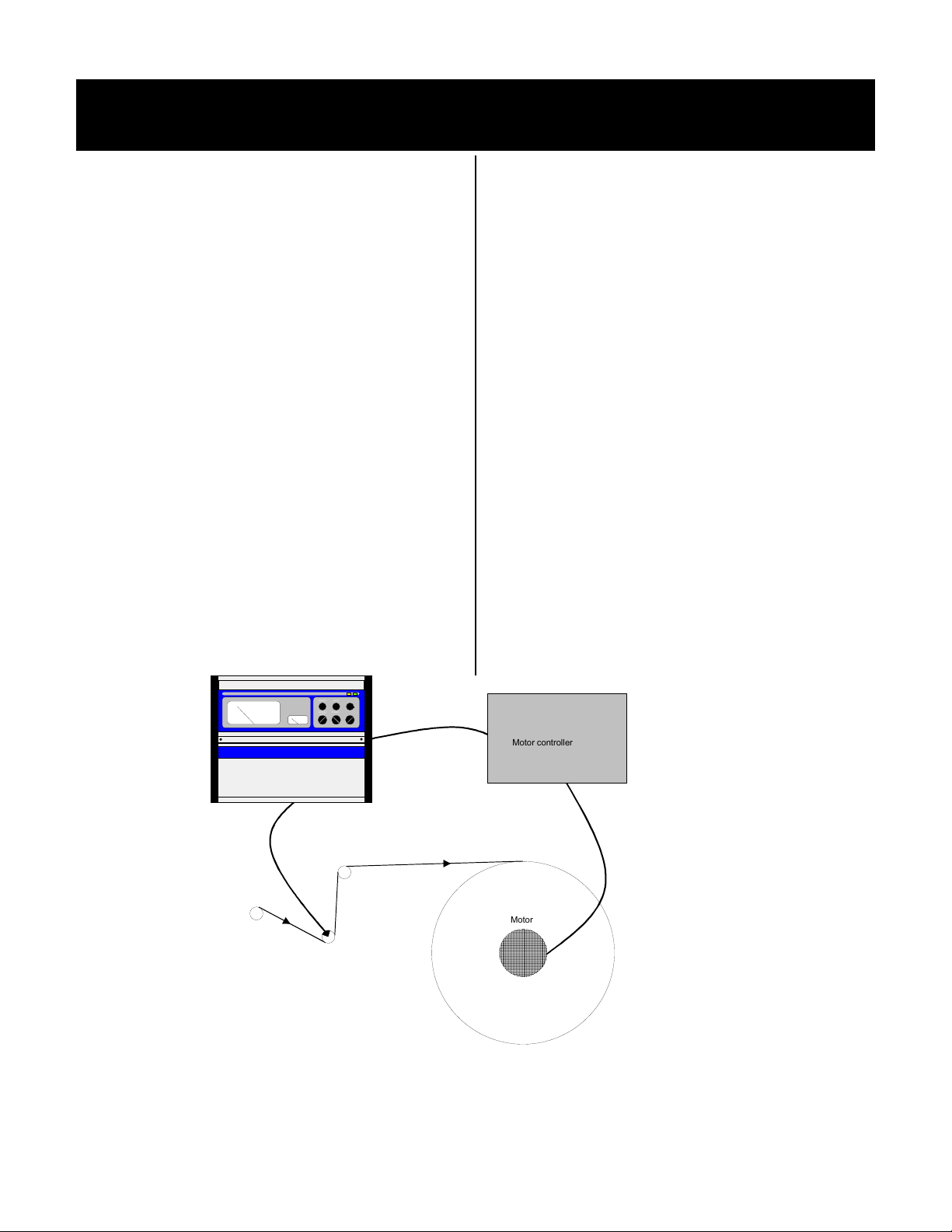
1 General Description
The Montalvo X-3000-ce PID analog controller
provides precise automatic control of web tension. The
progressive PID regulator automatically compensates
for roll diameter. The X-3000-ce is used in a closed
loop, of which the load cell roll and motor or clutch
are a part.
In order to properly set up and operate the X-3000-ce, as
well as be able to take advantage of all of the available
features, it is important to have a general understanding of
the controller and how it fits into the tensioning system
(please refer to the diagram below). The control outputs
of 4 to 20 mA and 0 to 10 volts DC enable the X-3000-ce
to interface with a variety of output devices to control web
tensioning brakes, clutches and motors.
Load Cell Function
Two load cells (also called transducers) are normally used.
The signals from the load cells are summed together to
give the total web tension across the entire web. Each load
cell contains 2 strain gauges connected in series. The two
load cells are connected so that the 4 strain gauges form a
Wheatstone bridge configuration supplied with ± 2.5V
DC. The web tension transfers a force to the load cell roll,
causing the resistance values in the bridge to change. The
resulting voltage change is amplified and calibrated at the
regulator card.
Motor/ Clutch Function
One or more motors may be controlled, converting the
electrical signal into torque. This torque in turn changes
the web tension.
Auto Mode Function (closed loop)
The operator sets the desired tension, using the auto
setpoint potentiometer. The feedback from the load cells
is calibrated to display the actual web tension. This signal
is compared with the desired tension (setpoint) and the
regulator automatically adjusts the output to make the
actual tension the same as the desired tension. Because the
web itself is part of the feedback loop, the X-3000-ce can
quickly compensate for speed and diameter changes, as
well as other factors that may affect tension during the
process.
Manual Mode Function (open loop)
The operator sets the desired output torque, using the
manual potentiometer. The web tension is still measured
and displayed on the tension meter, but no automatic
regulation is done in this mode. The operator must make
constant adjustments to maintain tension.
OUTPUT
MANUAL
50
20 80
20 805020 80
TENSION
MANUAL/
OFF / ON
AUTO
Load cell
AUTO
TAPER
50
LOW /
HIGH
Motor controller
Motor
2
2 Technical Data
2.1 X-3000-ce Electrical
AC Input
115 or 230 VAC ± 10 % (IEC TC77B WG3)
48 to 62 Hz
Fuse Size
115 V - 160 mA T (slow-blowing type) Ø 5 - 20 mm
230 V - 80 mA T (slow-blowing type) Ø 5 - 20 mm
Overvoltage Category
II (IEC 664)
2 kV in 1 min. Primary to secondary
Pollution Degree
3
Material Fire Classification
94V0
Max. Power Consumption
12 VA
Max. Fuse ahead
10A
Noise Immunity
EN 50082-2 industrial
Noise Emission
EN 50081-1
Load Cell Supply
± 2.5 VDC ± 5%
Load Cell Input
0 to ± 250 mVDC
Zero Range (tare)
50 % of load cell rating
Calibration Range
Gain - 11 to 480
Temperature Range
0 to 50 ° C (32 to 122° F) operating
-10 to 80°C (14 to 176° F) storage
Degree of Protection
IP 54
Regulator Outputs
0 to 10 VDC
Maximum load - 5 mA
4 - 20 mA / 0-20 mA
R
= 0 to 1000 Ω
L
Meter Outputs
0 to 100 µA
R
= 100 KΩ
O
0 to 10 VDC
Maximum load - 5 mA
Analog Input Voltage
0 to 10 VDC
= 1000K
R
I
Digital Input Voltage
15 to 30 VDC
= 10K
R
I
Digital Output Voltage
24V DC ± 15%
Maximum load - 100mA
Total load 4 outputs 350mA
Standards
Designed to meet UL 508 and EN 60204
2.2 X-3000-ce Mechanical
Dimensions L x W x H
330 x 260 x 163 mm
Weight
4 kgs
MANUAL
20
805020 805020 80
TENSION
MANUAL/
OUTPUT
OFF / ON
AUTO
Dimensions L x W x H Panel version
160 x 160 x 60 mm
Weight Panel version
1.0 kg
AUTO
TAPER
50
LOW /
HIGH
L N PE
L N PE
Type : X/D-3000
Serial no : 960034
Voltage : 115V/230V AC
Current : 160mA/80mA
TENSION 45 %
R1 R2 R3 R4 R5 R6
45 46 47 48 49 50 51 52 53 54 55 56 57 58
15 16 17 18 19 20 21 22 23 24 25 26 27 28 29
44
1 42 43
11 12 13 14
40 4
DO 1-4
DI 1-8
1 2 3 4 5 6 7 8 9 10
30 31 32 33 34 35 36 37 38 39
3

3 Installation
3.1 Controller Mounting
The X-3000-ce should be mounted in a dry place, away from
any source of heat. The mounting surface should be free of
any excessive vibration. If possible, the controller should be
mounted at eye level and in a location that is accessible to the
operator. If an I/P converter is used, it should be mounted as
close to the brake as possible.
3.2 Electrical Installation
Warning: The electrical installation must be done
by skilled personnel. Wiring must meet all
applicable codes and standards.
Refer to the appropriate wiring and terminal descriptions for
external connections.
Be sure the voltage selector on the regulator PCB is in the
correct position for the voltage supplied.
The PCB fuse size must be selected according to the input
voltage selected. The maximum external fuse on the input is
10 A.
If using load cell cables that mate to Amphenol connectors on
the bottom of the cabinet, the “G” (shield) end of the cable
connects to the X-3000-ce.
Please note: 0V DC and PE is internally connected.
Please note: Double check the accuracy of all wiring
connections before applying power to the controller.
Damage caused by improper wiring is not covered under
warranty.
Avoid mounting the circuit board close to drive
controllers or any other equipment that produces large
amounts of EMI.
EMC Requirements
The protective ground wire must be connected to the terminal
marked PE. Ground wires should be as short as possible.
For printed circuit board versions, PE, the mounting plate and
the cabinet must be connected to a common ground.
Shielded cable must be used for all external connections and
the shield terminated at the controller end only for analog
signals and at both ends for digital signals. For enclosure
versions, the shield may be connected to the cabinet at the
point where the cable enters, either to a bus bar or to the
connector housing. Keep the shield as short as possible (not
to exceed 10 mm or 0.4 inches). The best way to connect a
shield is to unisolate a piece and put a holder 360° around the
cable.
Keep signal cables away from supply cables or any wires
that conduct high current. For best noise immunity, run
signal cables close to the machine frame, mounting plates or
other grounded structures.
4
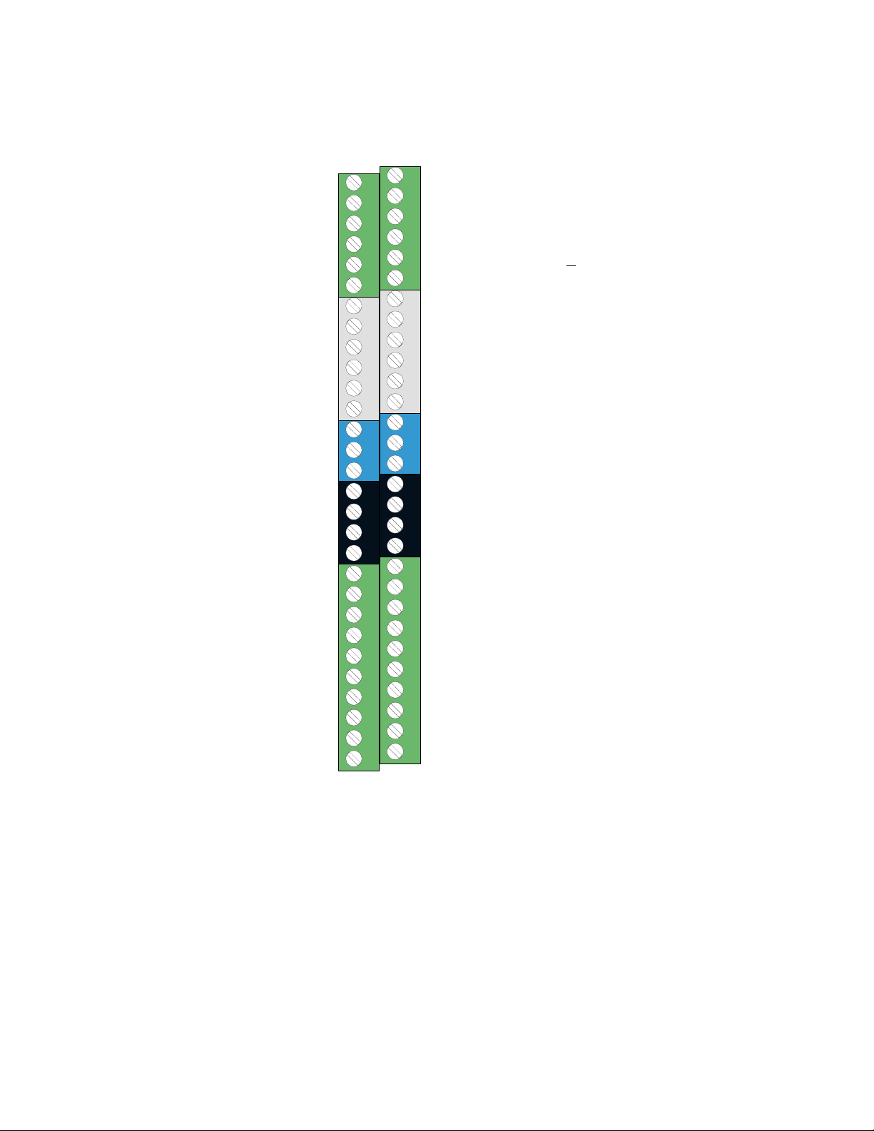
3.3 Terminal Blocks
Input for extra output 4-20mA/0-20mV
Extra analog output 0-10V
0VDC
External gain 0-10V
Summation input 0-20V
0VDC
+10V
Splice setpoint 0-10V
0VDC
+10V
Manual setpoint 0-10V
0VDC
Tension output 0-100uA
Tension output 0-10V
0VDC
-2.5V
-Load cell input
+2.5V
0VDC
DO3
WB / DO1
0VDC
+24V
Brake Pulse DI7
Start / DI5
+24V
Tension OFF / DI3
Manual / DI1
0VDC
45 46 47 48 49 50 51 52 53 54 55 56 57 58
44
1 42 43
40 4
30 31 32 33 34 35 36 37 38 39
Extra output 4-20mA/0-20mA
0VDC
+10V
-10V
Diameter/trim input +
10V
0VDC
Diameter output calibrated 0-10V
Taper setpoint 0-10V
0VDC
+10V
Auto setpoint 0-10V
0VDC
Regulator output 0-10V
Regulator output 4-20mA
0VDC
15 16 17 18 19 20 21 22 23 24 25 26 27 28 29
+2.5V
+Load cell input, dancer input
-2.5V
11 12 13 14
0VDC
DO4
DO2
0VDC
+24V input for DO
DI8 Inertia
DI6 Web Pulse
+24V
DI4 / High calibration
DI2 / Splice
0VDC
1 2 3 4 5 6 7 8 9 10
5
3.4 Terminal Block Descriptions
Basic Connections - Required for All Applications
115 / 230 VAC Supply
The controller must be supplied with the voltage indicated on
the voltage selector switch on the printed circuit board.
X10.1 Supply Voltage - L
X10.2 Supply Voltage - N
X10.3 PE - Ground
For protective conductor.
Regulated Outputs
X1.15 0V DC
Regulated voltage or current signal common. Connects to
input ground of the converter.
X1.17 Regulated Voltage
0 to 10 V output corresponding to 0 to maximum output from
the regulator. Used for recorder or output meter. May also
be used to control variable speed drives operating in the
torque mode. Maximum load = 5 mA.
X1.16 Regulated Current
Regulated current signal to the I/P or other converter for
clutch.
4-20 mA signal
1 +
2 -
Supplies
X1.4,33,36 +24 V Supply
Unregulated 22 to 28 volt DC supply for external
use. Maximum load - 100 ma.
X1.1,8,11,15,18,21,24,28,30,37,40,44,,47,50,53,56
0V DC
Common for signal and contact inputs and outputs.
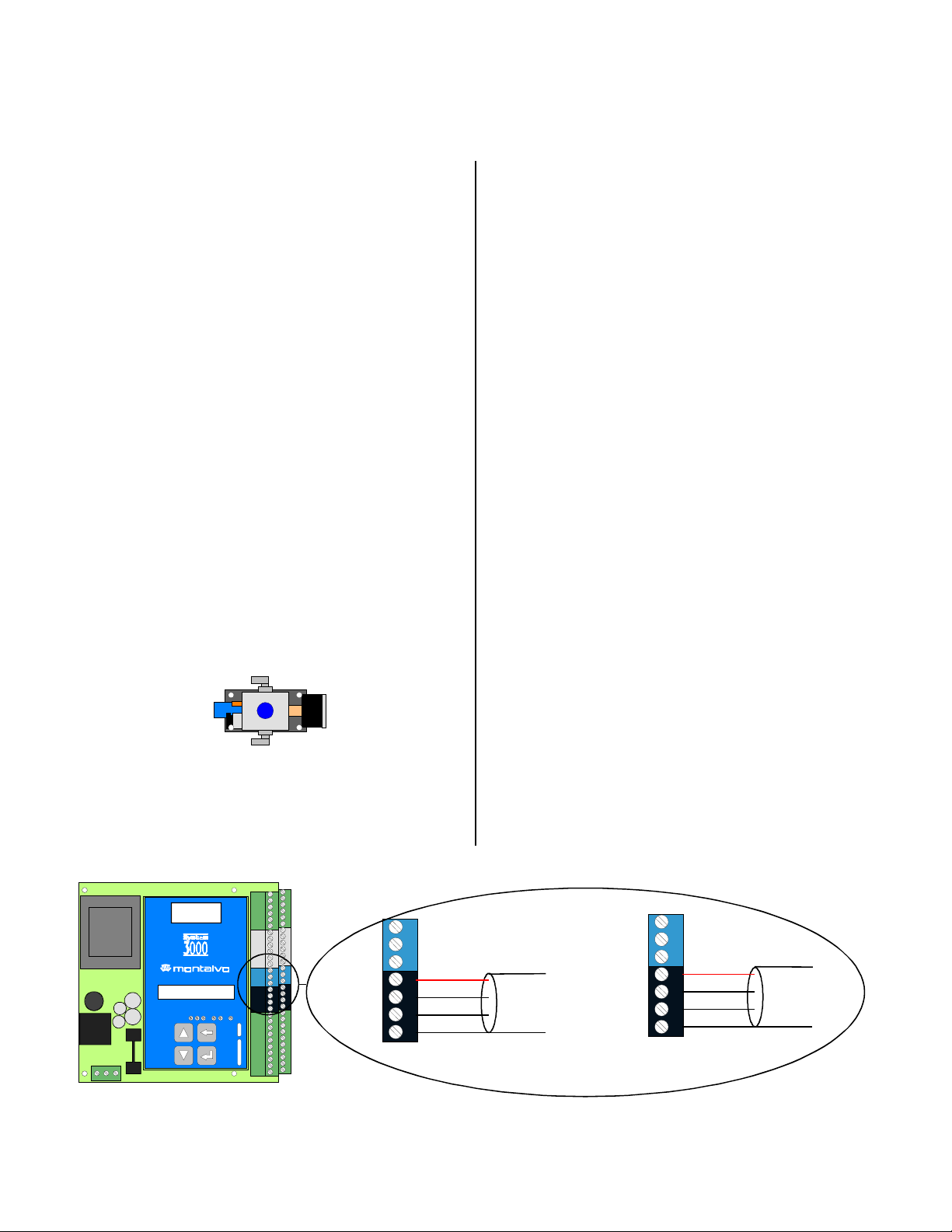
Load Cell Connections
The following connections are necessary only when wiring
the load cells directly into the printed circuit board. If
Amphenol connectors are used, these connections have been
made at the factory.
X1.12 - 2.5 V Supply
Connects to pin ‘b’ on load cell 1. Black wire.
X1.13 + Load Cell Input
Positive-going load cell input. Connects to pin ‘a’ on load
cell 1. White wire.
X1.14 +2.5 V Supply
Connects to pin ‘c’ on load cell 1. Red wire.
X1.41 + 2.5 V Supply
Connects to pin ‘b’ on load cell 2. Black wire.
X1.42 - Load Cell Input
Negative-going load cell input. Connects to pin ‘a’ on load
cell 2. White wire.
X1.43 -2.5 V Supply
Connects to pin ‘c’ on load cell 2.
Red wire.
Type : X/D-3000
Serial no : 960 034
Voltage : 115V/230V AC
L N PE
L N PE
Current : 160mA/80mA
TENSION 45 %
R1 R2 R3 R4 R5 R6
45 46
44
45 46 47 48 49 50 51 52 53 54 55 56 57 58
15 16 17 18 19 20 21 22 23 24 25 26 27 28 29
44
1 42 43
11 12 13 14
40 4
DO 1-4
DI 1-8
1 2 3 4 5 6 7 8 9 10
30 31 32 33 34 35 36 37 38 39
-2.5V
-INPUT
+2.5V
0VDC
RED
WHITE
1 42 43
BLACK
40 4
Colors ref. to standard cables supplied from Montalvo.
REGULATED VOLTAGE
REGULATED CURRENT
0VDC
+2.5V
LOAD CELL 2
CABLE
+INPUT
-2.5V
0VDC
15 16 17
RED
WHITE
BLACK
11 12 13 14
LOAD CELL 1
CABLE
6
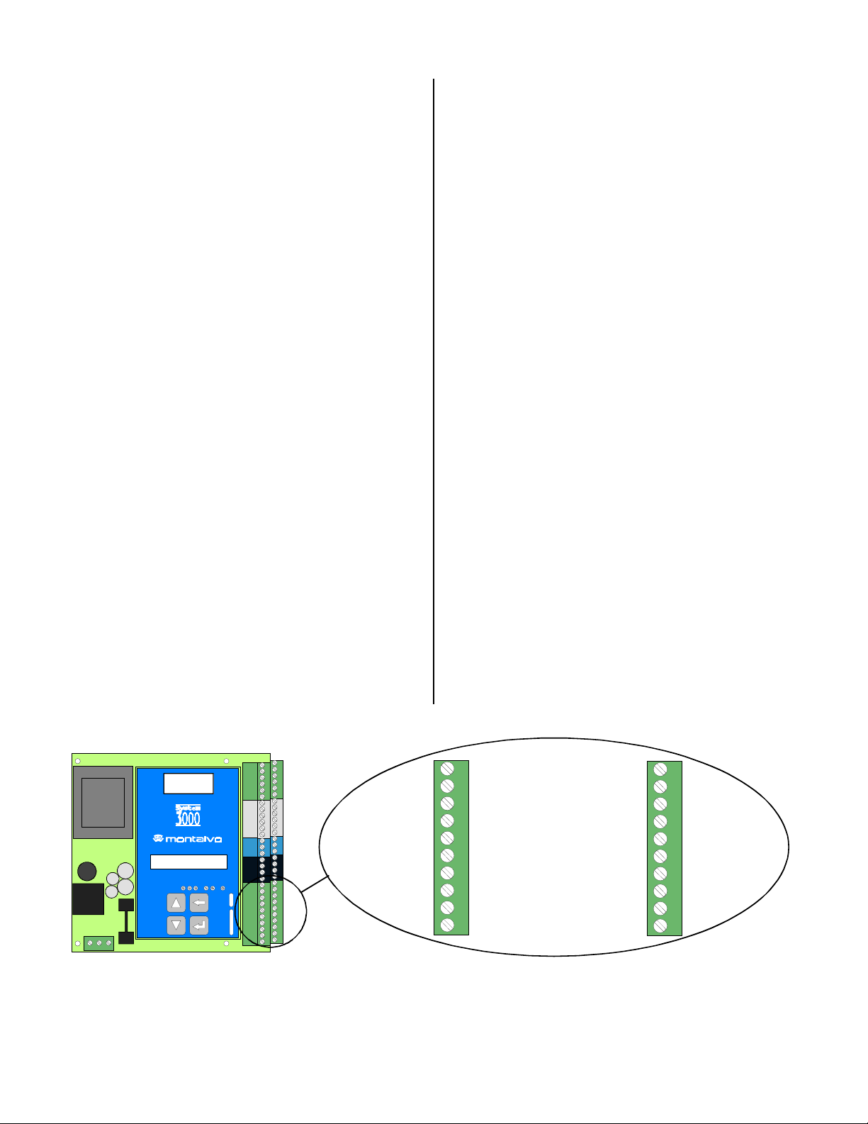
Optional Connections - Used for Rewind Applications
X1.50 0V DC
Connects to the CCW terminals (1) of the splice level potentiometer.
X1.51 Splice Level
Input for external signal is used to set output during splice
mode. A 0 to 10 volt input corresponds to 0 to maximum
output.
X1.52 10 V Reference
Reference voltage applied to the CW terminals (3) of the
splice level potentiometer. Total max. load 5mA.
X1.24 0V DC
Connects to the CCW terminals (1) of the diameter potentiometer.
X1.25 Diameter Input
Diameter reference input. Maximum 0 to 10 V with
reference to 0V DC. Signal may be supplied from a
potentiometer, ultrasonic sensor or diameter calculator.
X1.27 10 V Reference
Reference voltage applied to the CW terminals (3) of the
diameter potentiometer. Total max. load 5 mA.
X1.6 Inertia
When activated by a 24 V input or a contact to X1.36, the
output increases by a level set in the INERTIA menu. This
function is used to compensate for the mechanical inertia of
the rewind at start up. It is activated when the main drive is
started.
X1.31 Manual
When activated by a 24 V input or a contact closure to
X1.33, the controller switches to the manual mode. Output is
set by the potentiometer marked MANUAL. When deactivated, the controller regulates from the manual value.
X1.2 Splice
When activated by a 24 V input or a contact closure to X1.4,
the output switches immediately to the new roll, starting
output determined by the setting of the external splice level
potentiometer. This function is used for flying splice
automatic roll changes and is normally activated by the knife
firing circuit. Rewind splice level is typically set for 5 - 20 %
of maximum to provide the correct torque for the new core
diameter, but the actual setting depends on the application.
The splice level is held constant for a time determined by the
setting of the splice time in the SPLICE menu.
X1.34 Start
When activated by a 24 V input or a contact closure to
X1.34, the regulator is released and begins to integrate up to
the tension set point. Start should be activated when the
rewind motor is started.
X1.3 High Calibration
When activated by a 24 V input or a contact closure to X1.4,
the second calibration range is used. Calibration for this
range is adjusted by potentiometers R3. This feature is used
if the controller is used over a wide tension range or if there
are two different web paths.
X1.35 Roll Pulse
Puls from the rewind roll to calculate the diameter. There can
be more pulses per rev. The number of pulses is given in in
the DIAM. MENU. Max 80 Hz.
X1.5 Web Pulse
Pulses from the web each xx mm. The amount of mm per
pulse is given in in the DIAM.MENU. Max. 800 Hz.
X1.57 Calculated diameter output
0-10V DC output corresponding to the diameter calculated in
the controller.
L N PE
L N PE
Type : X/D-3000
Serial no : 960034
Voltage : 115V/230V AC
Current : 160mA/80mA
TENSION 45 %
R1 R2 R3 R4 R5 R6
DO3
DO1 WB
0VDC
+24V
45 46 47 48 49 50 51 52 53 54 55 56 57 58
15 16 17 18 19 20 21 22 23 24 25 26 27 28 29
44
1 42 43
11 12 13 14
40 4
DO 1-4
DI 1-8
30 31 32 33 34 35 36 37 38 39
1 2 3 4 5 6 7 8 9 10
ROLL PULSE
START
+24V
TENSION OFF
MANUAL
0VDC
30 31 32 33 34 35 36 37 38 39
+24V DC FOR DO
INERTIA(MAIN START)
WEB PULSE
HIGH CALIBRATION
DO4
DO2
0VDC
+24V
SPLICE
0VDC
Optional Connections - Rewind, Printed Circuit Board Version
1 2 3 4 5 6 7 8 9 10
7
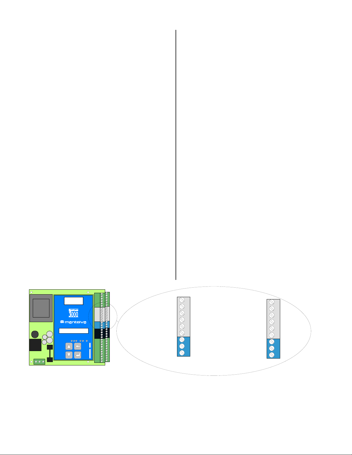
X1.47 0V DC
Connects to the CCW terminal (1) of the MANUAL
potentiometer. Use 10 k Ω potentiometer.
X1.48 Manual Input
0 to 10 volt input which corresponds to 0 to maximum output
from the controller when in the manual or soft start modes.
Connects to the wiper (2) of the MANUAL potentiometer.
X1.49 10 V Reference
Reference voltage applied to the CW terminal (3) of the
manual potentiometer. Total max. load 5 mA.
X1.18 0V DC
Connects to the CCW terminal (1) of the AUTO
potentiometer. Use 10 k Ω potentiometer.
X1.19 Auto Setpoint
0 to 10 volt input which corresponds to 0 to full scale tension
when the controller is in the auto mode. Connects to the
wiper (2) of the AUTO potentiometer.
X1.20 10 V Reference
Reference voltage applied to the CW terminal of the AUTO
potentiometer. Total max. load 5 mA.
X1.50 0V DC
Connects to the CCW terminals (1) of the splice level potentiometer. Use 10 k Ω potentiometer.
X1.51 Splice Level
Input for external signal is used to set output during splice
mode. A 0 to 10 volt input corresponds to 0 to maximum
output.
X1.52 10 V Reference
Reference voltage applied to the CW terminals (3) of the
splice level potentiometer. Total max. load 5 mA.
X1.24 0V DC
Connects to the CCW terminals (1) of the diameter potentiometer. Use 10 k Ω potentiometer.
X1.25 Diameter Input
Diameter reference input. Maximum 0 to 10 V with
reference to 0V DC. Signal may be supplied from a
potentiometer, ultrasonic sensor or diameter calculator.
X1.27 10 V Reference
Reference voltage applied to the CW terminals (3) of the
diameter potentiometer. Total max. load 5 mA.
X1.44 0V DC
Common for tension outputs.
X1.45 Tension, 0 to 10 V
0 to 10 volts proportional to 0 to full scale tension.
X1.46 Tension, 0 to 100 µA
0 to 100 µamp output proportional to 0 to full scale tension.
X1.23 Diameter Output
Amplified diameter output, adjusted for the correct span and
the points at which taper begins and ends.
Should be 0 volts at minimum diameter and 10 volts at
maximum. Connects to CW (3) of the taper %
potentiometer.
X1.22 Taper % Input
Adjusted diameter output signal, which allows the operator to
set the desired amount of taper. This input determines how
much the setpoint will be reduced as the roll increases in
diameter. If no taper is required, potentiometer may be set to
zero. Connects to the wiper (2) of the taper % potentiometer.
X1.21 0V DC
Connects to the CCW terminals (1) of the taper %
potentiometer.
Type : X/D-3000
Serial no : 960034
Voltage : 115V/230V AC
L N PE
L N PE
Current : 160mA/80mA
TENSION 45 %
R1 R2 R3 R4 R5 R6
45 46 47 48 49 50 51 52 53 54 55 56 57 58
15 16 17 18 19 20 21 22 23 24 25 26 27 28 29
44
1 42 43
11 12 13 14
40 4
DO 1-4
DI 1-8
TENSION OUT. 0-100 uA
1 2 3 4 5 6 7 8 9 10
30 31 32 33 34 35 36 37 38 39
SPLICE SETP.
TENSION OUT. 0-10V
+10V
0VDC
+10V
MAN. SETP.
0VDC
0VDC
45 46 47 48 49 50 51 52
44
DIAMETER OUTP. CAL.
TAPER SETP.
0VDC
+10V
AUTO SETP.
0VDC
REG OUT 0-10V
REG OUT 4-20mA
0VDC
15 16 17 18 19 20 21 22 23
8
 Loading...