

www.montalvo.com / Technical details subject to change without notice. Mamp-technical manual-US-07 © Montalvo
EST
.
1947
207-856-2501 / 800-226-8710
+86-21-52188010
+45 75 57 27 11
+49 (0)511 760 691 41
Need help installing?
www.montalvo.com
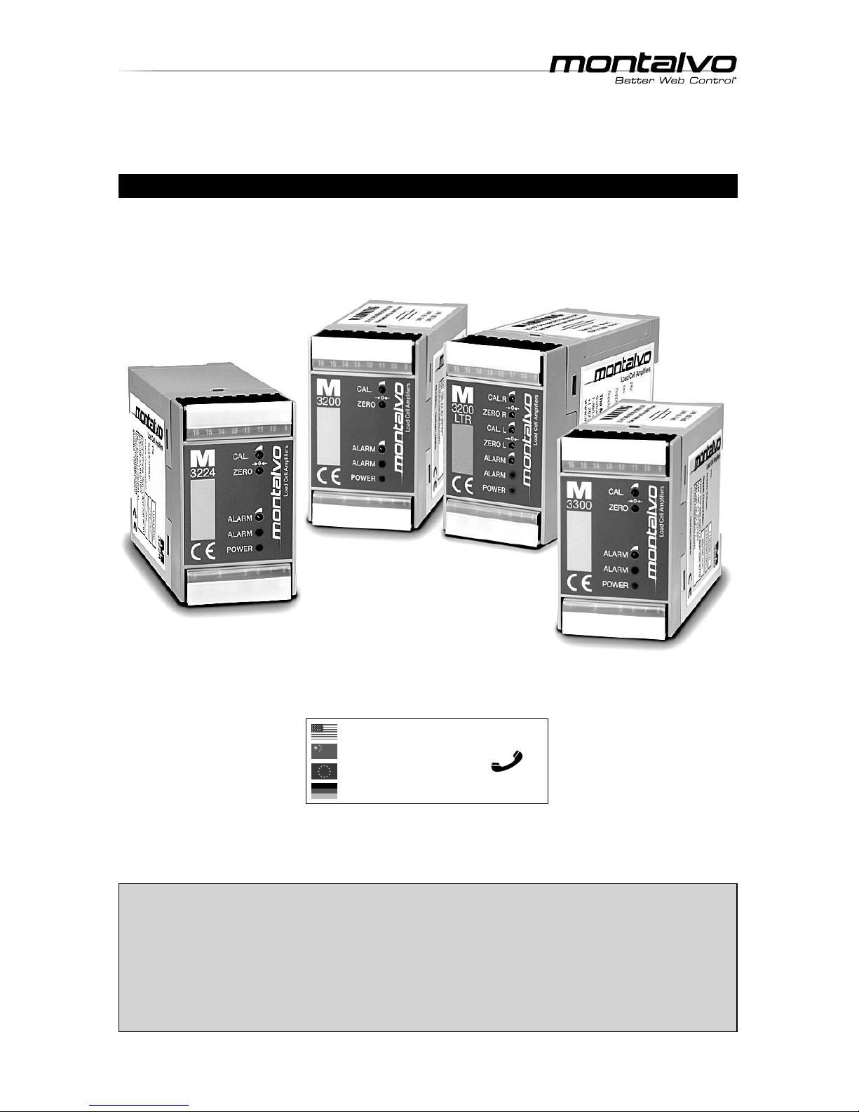
TECHNICAL MANUAL
M Series Ampli er Modules
For Models M3200, M3224, M3200LTR and M3300
Publication Date: 04/22/2019
EST
.
1947
p. 2
M Series Ampli er
__ ___________________________________________________________________________________
Technical Manual
INDEX
www.montalvo.com / Technical details subject to change without notice. Mamp-technical manual-US-07 © Montalvo
Con guration
DIP Switches ............................................................................................3
Fuses ........................................................................................................3
DIP Switch / Fuse Location .......................................................................3
Wiring
M3200 ......................................................................................................4
M3224 ......................................................................................................6
M3200LTR ................................................................................................8
M3300 ....................................................................................................10
Calibration
Zero Point ...............................................................................................12
Calibration ...............................................................................................12
Alarm Level Adjustment .................................................................................13
Speci cations
Technical Data .........................................................................................14
M
3200
1 : Line L
2 :
3 : Line N
4 :
5 : Ground PE
6 : Ground
7 : NC.
8 : NC.
9 : +2.5V Supply
10 : + input +/- 250 mV
11 : - input +/- 250 mV
12 : -2.5V Supply
13 : Total output 0-10V / 0-100μA
14 : Total output 4-20mA / 0-20mA / 0-10V
15 : Ground (0VDC)
16 : Alarm output
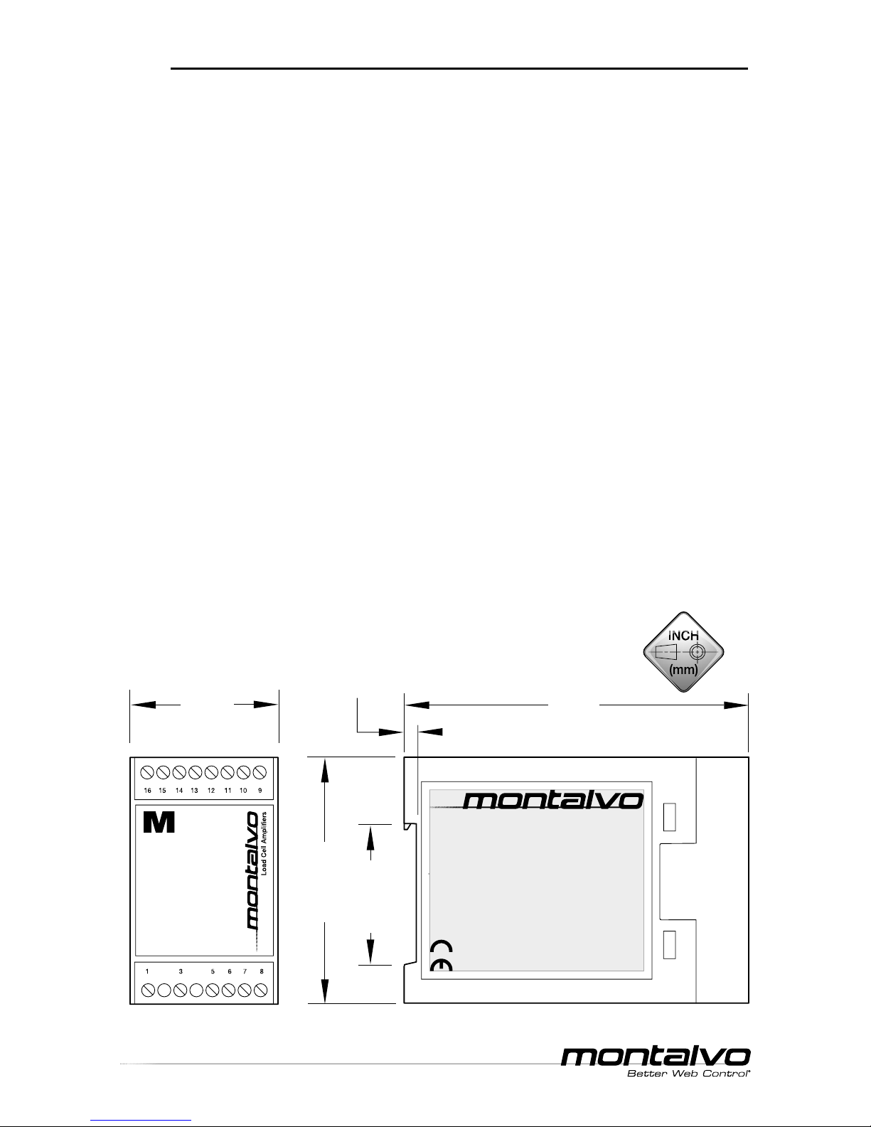
2.95 (75)
4.13
(105)
1.77
(45)
1.42 (36)
0.16 (4)
Load Cell Ampliers
M
Dimensions
EST
.
1947
M Series Ampli er
__ ___________________________________________________________________________________
Technical Manual
p. 3
www.montalvo.com / Technical details subject to change without notice. Mamp-technical manual-US-07 © Montalvo
CONFIGURATION
Model
DIP Switch Settings
Output
Terminal
Affected
1**2**3456
3200
3224
3200LTR
M3300
--ON* ---
Total
0-10V*
13
- - OFF - - - 0-100A
---OFF* ON* OFF* 4-20mA*
14- - - ON OFF OFF 0-20mA
- - - ON OFF ON 0-10V
3200LTR
- ON* ----
Left
0-10V*
7
-OFF---- 0-100A
ON* -----
Right
0-10V*
8
OFF----- 0-100A
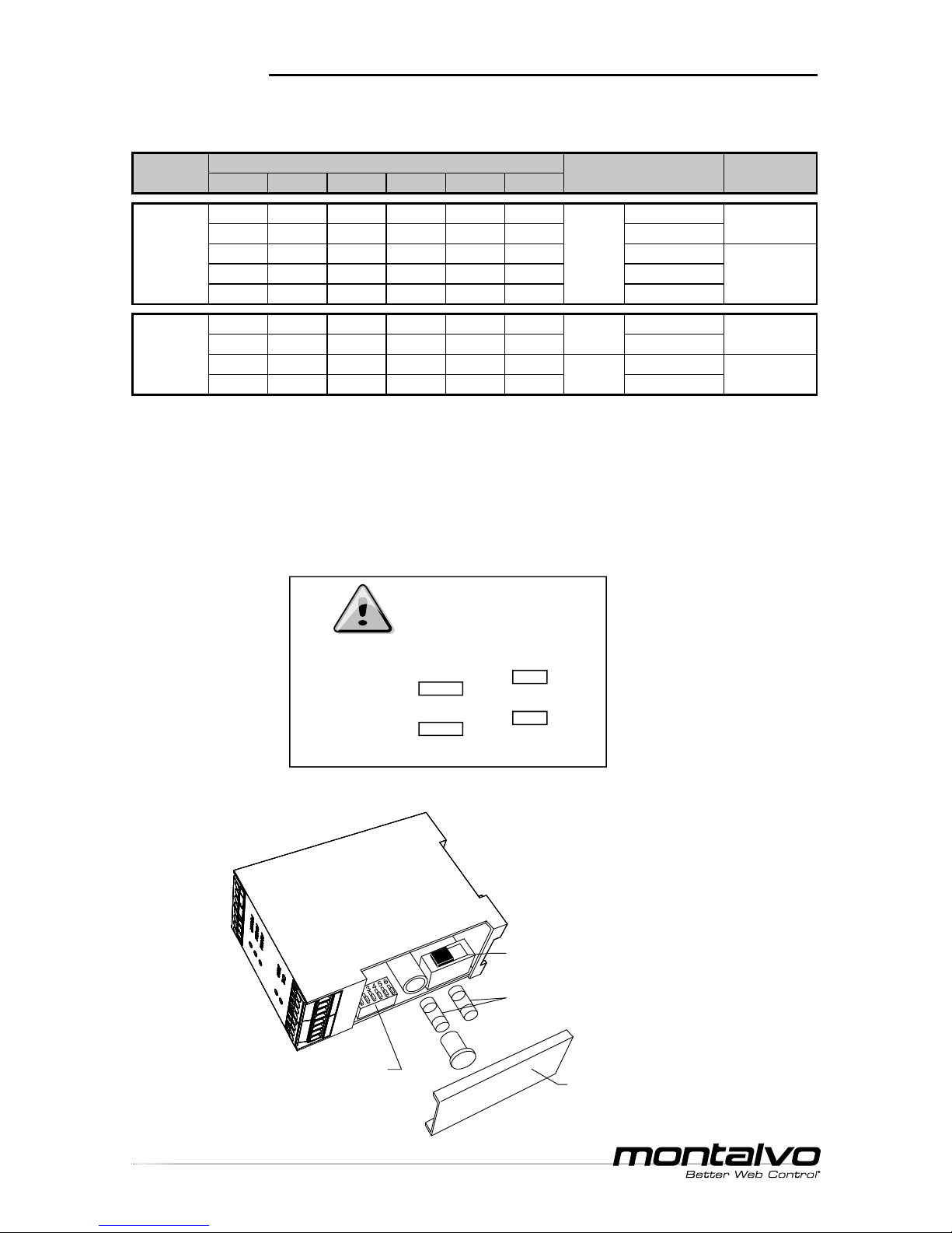
DIP Switches
Fuses
The M3200, M3200LTR and M3300 ship from the factory with fuses NOT
installed. Install the appropriate supplied fuse to match the voltage being used.
The M3224 has a resettable fuse to match the required 24V power supply.
DIP Switch / Fuse Location
* Indicates factory setting.
** DIP switches 1 and 2 have no affect on M3200 and M3224.
This module must be set up for the actual supply voltage.
If power supply is 115V
Step 1 Set power selector in position 115V
Step 2 Mount fuse 80mA T
If power supply is 230V
Step 1 Set power selector in position 230V
Step 2 Mount fuse 50mA T
Note: Power selector and fuses are
found under cover on top of module.
Caution
Failure to follow instructions
may result in equipment
damage or personal injury.
Montalvo
M3200/M3300
Amplier Modules
230
DIP Switches
(1 thru 6)
POWER Switch (AC units only)
(115V or 230V - factory set to 230V)
Cover
(Fuse NOT installed on new units must be installed before operation)
FUSES (AC units only)
(115V or 230V - ships with both)

EST
.
1947
p. 4
M Series Ampli er
__ ___________________________________________________________________________________
Technical Manual
www.montalvo.com / Technical details subject to change without notice. Mamp-technical manual-US-07 © Montalvo
WIRING
M3200 Overview
M3200 Dip Switch Factory Settings
Line L (1)
Line N (3)
Total Output 0-10V / 0-100µA (13)
Total Output 4-20mA / 0-20mA / 0-10V (14)
Ground (0V DC) (15)
Alarm Output (16)
(8) No Connection
(7) No Connection
(6) Ground
(5) Ground PE
(12) - 2.5V Supply
(11) - Input ± 250mV
(10) + Input ± 250mV
(9) + 2.5V Supply (excitation)
16 15
14
13 12
11
10
9
1
3
5
6
7
8
123456
y
ON
See Con guration section (p.3)
for optional DIP switch settings.
EST
.
1947
M Series Ampli er
__ ___________________________________________________________________________________
Technical Manual
p. 5
www.montalvo.com / Technical details subject to change without notice. Mamp-technical manual-US-07 © Montalvo
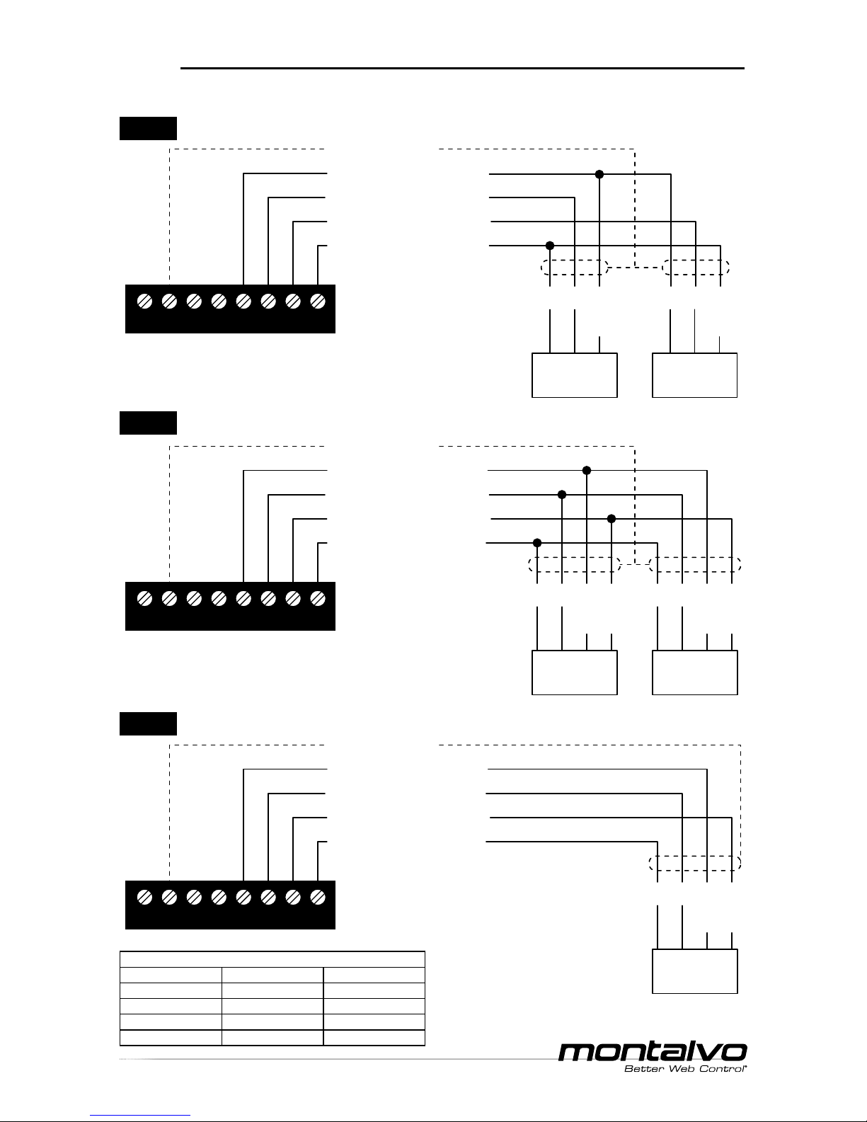
WIRING
(15) Ground (0V DC)
(12) - 2.5V Supply (excitation)
(11) - Input ± 250mV (signal)
(10) + Input ± 250mV (signal)
(9) + 2.5V Supply (excitation)
BK WH BN
or
RD
16 15
14
13 12
11
10
9
BK WH BN
or
RD
#1
Load Cell
#2
Load Cell
(15) Ground (0V DC)
(12) - 2.5V Supply (excitation)
(11) - Input ± 250mV (signal)
(10) + Input ± 250mV (signal)
(9) + 2.5V Supply (excitation)
BK WH BN
or
RD
BL
or
GN
16 15
14
13 12
11
10
9
#1
Load Cell
BK WH BN
or
RD
BL
or
GN
#2
Load Cell
(15) Ground (0V DC)
(12) - 2.5V Supply (excitation)
(11) - Input ± 250mV (signal)
(10) + Input ± 250mV (signal)
(9) + 2.5V Supply (excitation)
16 15
14
13 12
11
10
9
BK WH BN
or
RD
BL
or
GN
Load Cell
* If using only a single half bridge load cell,
connect as shown for #2 load cell.
M3200 Dual Full Bridge Semiconductor Strain Gauge Load Cells
M3200 Single Full Bridge Semiconductor Strain Gauge Load Cell
Standard conductor colors for Montalvo load cell cables
4 pin connector 6 pin connector 3 pin connector
Brown (BN) Red (RD) Red (RD)
White (WH) White (WH) White (WH)
Black (BK) Black (BK) Black (BK)
Blue (BU) Green (GN) NA
M3200 Dual* Half Bridge Semiconductor Strain Gauge Load Cells

EST
.
1947
p. 6
M Series Ampli er
__ ___________________________________________________________________________________
Technical Manual
www.montalvo.com / Technical details subject to change without notice. Mamp-technical manual-US-07 © Montalvo
WIRING
M3224 Overview
No Connection (1)
+24V DC Supply (2)
No Connection (3)
Ground Supply (0V DC) (4)
Total Output 0-10V / 0-100µA (13)
Total Output 4-20mA / 0-20mA / 0-10V (14)
Ground (0V DC) (15)
Alarm Output (16)
(8) No Connection
(7) No Connection
(6) Ground (0V DC)
(5) Ground PE
(12) - 2.5V Load Cell Supply (excitation)
(11) - Input ± 250mV (signal)
(10) + Input ± 250mV (signal)
(9) + 2.5V Load Cell Supply (excitation)
16 15
14
13 12
11
10
9
1 24V
24V 0V
0V
3
PE
6
7
8
M
3224
123456
y
ON
See Con guration section (p.3)
for optional DIP switch settings.
M3224 Dip Switch Factory Settings

EST
.
1947
M Series Ampli er
__ ___________________________________________________________________________________
Technical Manual
p. 7
www.montalvo.com / Technical details subject to change without notice. Mamp-technical manual-US-07 © Montalvo
WIRING
(15) Ground (0V DC)
(12) - 2.5V Supply (excitation)
(11) - Input ± 250mV (signal)
(10) + Input ± 250mV (signal)
(9) + 2.5V Supply (excitation)
BK WH BN
or
RD
16 15
14
13 12
11
10
9
BK WH BN
or
RD
#1
Load Cell
#2
Load Cell
(15) Ground (0V DC)
(12) - 2.5V Supply (excitation)
(11) - Input ± 250mV (signal)
(10) + Input ± 250mV (signal)
(9) + 2.5V Supply (excitation)
BK WH BN
or
RD
BL
or
GN
16 15
14
13 12
11
10
9
#1
Load Cell
BK WH BN
or
RD
BL
or
GN
#2
Load Cell
(15) Ground (0V DC)
(12) - 2.5V Supply (excitation)
(11) - Input ± 250mV (signal)
(10) + Input ± 250mV (signal)
(9) + 2.5V Supply (excitation)
16 15
14
13 12
11
10
9
BK WH BN
or
RD
BL
or
GN
Load Cell
* If using only a single half bridge load cell,
connect as shown for #2 load cell.
M3224 Dual* Half Bridge Semiconductor Strain Gauge Load Cells
M3224 Dual Full Bridge Semiconductor Strain Gauge Load Cells
M3224 Single Full Bridge Semiconductor Strain Gauge Load Cell
Standard conductor colors for Montalvo load cell cables
4 pin connector 6 pin connector 3 pin connector
Brown (BN) Red (RD) Red (RD)
White (WH) White (WH) White (WH)
Black (BK) Black (BK) Black (BK)
Blue (BU) Green (GN) NA

EST
.
1947
p. 8
M Series Ampli er
__ ___________________________________________________________________________________
Technical Manual
www.montalvo.com / Technical details subject to change without notice. Mamp-technical manual-US-07 © Montalvo
WIRING
M3200LTR Overview
Line L (1)
Line N (3)
Total Output 0-10V / 0-100µA (13)
Total Output 4-20mA / 0-20mA / 0-10V (14)
Ground (0V DC) (15)
Alarm Output (16)
(8) Right Output 0-10V / 0-100µA
(7) Left Output 0-10V / 0-100µA
(6) Ground
(5) Ground PE
(12) - 2.5V Supply (excitation)
(11) Left - Input ± 250mV (signal)
(10) Right + Input ± 250mV (signal)
(9) + 2.5V Supply (excitation)
16 15
14
13 12
11
10
9
1
3
5
6
7
8
CAL. R
ZERO R
CAL. L
ZERO L
ALARM
ALARM
POWER
Load Cell Ampliers
M
3200
LTR
0
0
123456
y
ON
See Con guration section (p.3)
for optional DIP switch settings.
M3200LTR Dip Switch Factory Settings

EST
.
1947
M Series Ampli er
__ ___________________________________________________________________________________
Technical Manual
p. 9
www.montalvo.com / Technical details subject to change without notice. Mamp-technical manual-US-07 © Montalvo
WIRING
(15) Ground (0V DC)
(12) - 2.5V Supply (excitation)
(11) Left - Input ± 250mV (signal)
(10) Right + Input ± 250mV (signal)
(9) + 2.5V Supply (excitation)
BK WH BN
or
RD
16 15
14
13 12
11
10
9
BK WH BN
or
RD
#1 (LEFT)
Load Cell
#2 (RIGHT)
Load Cell
(15) Ground (0V DC)
(12) - 2.5V Supply (excitation)
(11) Left - Input ± 250mV (signal)
(10) Right + Input ± 250mV (signal)
(9) + 2.5V Supply (excitation)
BK WH BN
or
RD
BL
or
GN
16 15
14
13 12
11
10
9
#1 (LEFT)
Load Cell
BK WH BN
or
RD
BL
or
GN
#2 (RIGHT)
Load Cell
(15) Ground (0V DC)
(12) - 2.5V Supply (excitation)
(11) Left - Input ± 250mV (signal)
(10) Right + Input ± 250mV (signal)
(9) + 2.5V Supply (excitation)
16 15
14
13 12
11
10
9
BK WH BN
or
RD
BL
or
GN
Load Cell
* If using only a single half bridge load cell,
connect as shown for #2 load cell.
M3200LTR Dual* Half Bridge Semiconductor Strain Gauge Load Cells
M3200LTR Dual Full Bridge Semiconductor Strain Gauge Load Cells
M3200LTR Single Full Bridge Semiconductor Strain Gauge Load Cell
Standard conductor colors for Montalvo load cell cables
4 pin connector 6 pin connector 3 pin connector
Brown (BN) Red (RD) Red (RD)
White (WH) White (WH) White (WH)
Black (BK) Black (BK) Black (BK)
Blue (BU) Green (GN) NA

EST
.
1947
p. 10
www.montalvo.com / Technical details subject to change without notice. Mamp-technical manual-US-07 © Montalvo
M Series Ampli er
__ ___________________________________________________________________________________
Technical Manual
WIRING
Line L (1)
Line N (3)
Total Output 0-10V / 0-100µA (13)
Total Output 4-20mA / 0-20mA / 0-10V (14)
Ground (0V DC) (15)
Alarm Output (16)
(8) No Connection
(7) No Connection
(6) Ground
(5) Ground PE
(12) - 5VDC Supply
(11) - Input ± 30mVDC
(10) + Input ± 30mVDC
(9) + 5VDC Supply (excitation)
16 15
14
13 12
11
10
9
1
3
5
6
7
8
M3300 Overview
M3300 Dip Switch Factory Settings
123456
y
ON
See Con guration section (p.3)
for optional DIP switch settings.

EST
.
1947
M Series Ampli er
__ ___________________________________________________________________________________
Technical Manual
p. 11
www.montalvo.com / Technical details subject to change without notice. Mamp-technical manual-US-07 © Montalvo
WIRING
M3300 Dual* Half Bridge Foil Gauge Load Cells
(15) Ground (0V DC)
(12) - 5V Supply (excitation)
(11) - Input ± 30mV (signal)
(10) + Input ± 30mV (signal)
(9) + 5V Supply (excitation)
BK WH BN
or
RD
16 15
14
13 12
11
10
9
BK WH BN
or
RD
#1
Load Cell
#2
Load Cell
(15) Ground (0V DC)
(12) - 5V Supply (excitation)
(11) - Input ± 30mV (signal)
(10) + Input ± 30mV (signal)
(9) + 5V Supply (excitation)
BK WH BN
or
RD
BL
or
GN
16 15
14
13 12
11
10
9
#1
Load Cell
BK WH BN
or
RD
BL
or
GN
#2
Load Cell
(15) Ground (0V DC)
(12) - 5V Supply (excitation)
(11) - Input ± 30mV (signal)
(10) + Input ± 30mV (signal)
(9) + 5V Supply (excitation)
16 15
14
13 12
11
10
9
BK WH BN
or
RD
BL
or
GN
Load Cell
* If using only a single half bridge load cell,
connect as shown for #2 load cell.
Standard conductor colors for Montalvo load cell cables
4 pin connector 6 pin connector 3 pin connector
Brown (BN) Red (RD) Red (RD)
White (WH) White (WH) White (WH)
Black (BK) Black (BK) Black (BK)
Blue (BU) Green (GN) NA
M3300 Dual Full Bridge Foil Gauge Load Cells
M3300 Single Full Bridge Foil Gauge Load Cell

EST
.
1947
p. 12
M Series Ampli er
__ ___________________________________________________________________________________
Technical Manual
www.montalvo.com / Technical details subject to change without notice. Mamp-technical manual-US-07 © Montalvo
CALIBRATION
Zero Point
1 Connect power and load cells to M Series Ampli er as described in
WIRING section.
2 With web removed and no tension on load cell roller, adjust ZERO
potentiometer using a voltmeter:
Note: A remote meter can be used to zero the 3200/3224. Connect
meter (see WIRING section) and adjust ZERO potentiometer until
meter reads 0.
Calibration
3 Select a weight that is at least 25% of the full scale tension range expected
to be present on the load cells.
4 Suspend the weight from a non-elastic rope or strap that has been fed
through the rollers of the machine exactly as the feed material will be in the
application. It is important that the rope match the wrap angles on the
tension sensing roller that will be used when the machine is running.
Known
Weight
Rope fastened
to this roller
Load Cell
Roller
Model Output Potentiometer Connections Reading
3200/3224
M3300
Total ZERO 13 (+) 15 (-) 0V
3200LTR
Left ZERO L 7 (+) 6 (-) 0V
Right ZERO R 8 (+) 6 (-) 0V

EST
.
1947
M Series Ampli er
__ ___________________________________________________________________________________
Technical Manual
p. 13
www.montalvo.com / Technical details subject to change without notice. Mamp-technical manual-US-07 © Montalvo
CALIBRATION
5 Rotate all of the rollers the rope wraps around in the direction of the weight.
This is done to counteract friction forces on the rope to the rollers, which
may cause inaccurate readings.
6 Adjust potentiometer(s) using a voltmeter:
*
Output voltage value = V. Calculated by the following formula:
V = (calibration weight/CAL. full-scale value) x 10 volts
Note: A remote meter can be used to calibrate the 3200/3224.
Connect meter (see WIRING section) and adjust CAL. potentiometer
until meter displays calibration weight.
7 Remove weight. Output should return to 0. If not, repeat steps 2, 5 and
` 6 while verifying calibration weight. Repeat as necessary until 0 and
calibrated weights are accurate.
Model Output Potentiometer Connections Reading
3200/3224
M3300
Total CAL. 13 (+) 15 (-)
*
3200LTR
Left CAL. L 7 (+) 6 (-)
*
Right CAL. R 8 (+) 6 (-)
*
Alarm Level Adjustment
Apply a weight to the tension sensing roller equal to the value that should
activate the alarm. Adjust the ALARM potentiometer until the ALARM LED
lights up. Alarm output will be high (+24 V) whenever tension drops below
the alarm level.

EST
.
1947
p. 14
www.montalvo.com / Technical details subject to change without notice. Mamp-technical manual-US-07 © Montalvo
M Series Ampli er
__ ___________________________________________________________________________________
Technical Manual
SPECIFICATIONS
Supply Voltage M3200/M3200LTR/M3300 Selectable 115V/230V AC ± 10% (IEC 204-1)
Supply Voltage M3224 24VDC±15% (IEC60204-1)
Supply Frequency 48-62 Hz
Overvoltage Category II (IEC 664)
Maximum Internal Fuse Size 5x20mm 115V/80mA(T) / 230V/50mA(T)
Material Degree of In ammability UL94V0
Maximum Power Consumption 3.5 VA
Maximum Supply Fuse Size 10 A
Testing Voltage - Primary to Secondary 3.75 kV for 1 Minute
EMC-Immunity EN 50082-2, Industry
EMC-Emission EN 50081-1, Trade and Light Industry
Degree of Protection IP20 (IEC 529)
Installation Environment (Pollution Degree) 2
Connections Removable Terminal Blocks
Weight 0.14 lb (0.3 kg)
Dimension (L x W x H) 2.95 x 1.77 x 4.21 (75 x 45 x 107 mm)
Mounting DIN Rail 35 mm
Mounting Orientation Not Critical
Ambient Temperature Range: Operating 14°F to 122°F (-10°C to 50°C)
Ambient Temperature Range: Storing 14°F to 176°F (-10°C to 80°C)
Humidity < 95% Non-Condensing
Load Cell Input M3200/M2300LTR/M3224 ±250mVDC
Load Cell Input M3300 ±30mVDC
Input Impedance 100 KΩ
Load Cell Supply M3200/M2300LTR/M3224 ±2.5 VDC ±2%
Load Cell Supply M3300 ±5 VDC ±2%
Meter Output, Selectable 0 to 100μA / 0 to 10V, Max. Load 5 mA
Process Output, Selectable 0 to 20 mA / 4 to 20 mA / 0 to 10V
Process Output Load (Current) ≤ 500 Ω
Process Output Load (Voltage) > 5000 Ω
Zero Range Adj. M3200/M2300LTR/M3224 50% of Load Cell Rating [Max. 250 mVDC (±125 mV)]
Zero Range Adjustment M3300 300% of Load Cell Rating [Max. 60 mVDC (±30 mV)]
Gain Adjustment M3200/M2300LTR/M3224 11 to 510
Gain Adjustment M3300 90 to 4400
Accuracy Better Than 1%
Alarm Output Voltage 24 VDC ±15%
Alarm Output Load > 650 Ω

EST
.
1947
M Series Ampli er
__ ___________________________________________________________________________________
Technical Manual
p. 15
www.montalvo.com / Technical details subject to change without notice. Mamp-technical manual-US-07 © Montalvo
NOTES

EST
.
1947
p. 16
www.montalvo.com / Technical details subject to change without notice. Mamp-technical manual-US-07 © Montalvo
M Series Ampli er
__ ___________________________________________________________________________________
Technical Manual
Montalvo USA
(Corporate Headquarters)
Gorham, Maine 04038 USA
Tel: 1-800-226-8710
Tel: +1-207-856-2501
info@montalvo.com
Montalvo Europe ApS
Horsens, Denmark
Tel: +45 75 57 27 11
info.eu@montalvo.com
Montalvo Deutchland
Hannover, Germany
Tel: +49 (0)511 760 691 41
info.de@montalvo.com
Montalvo (Shanghai) Trading Co., Ltd.
Shanghai, China
Tel: +86-21-52188010
info.cn@montalvo.com
 Loading...