

Montalvo M3200, M, M3224, M3200LTR, M3300 Technical Manual
www.montalvo.com / Technical details subject to change without notice. Mamp-technical manual-US-07 © Montalvo
EST
.
1947
207-856-2501 / 800-226-8710
+86-21-52188010
+45 75 57 27 11
+49 (0)511 760 691 41
Need help installing?
www.montalvo.com
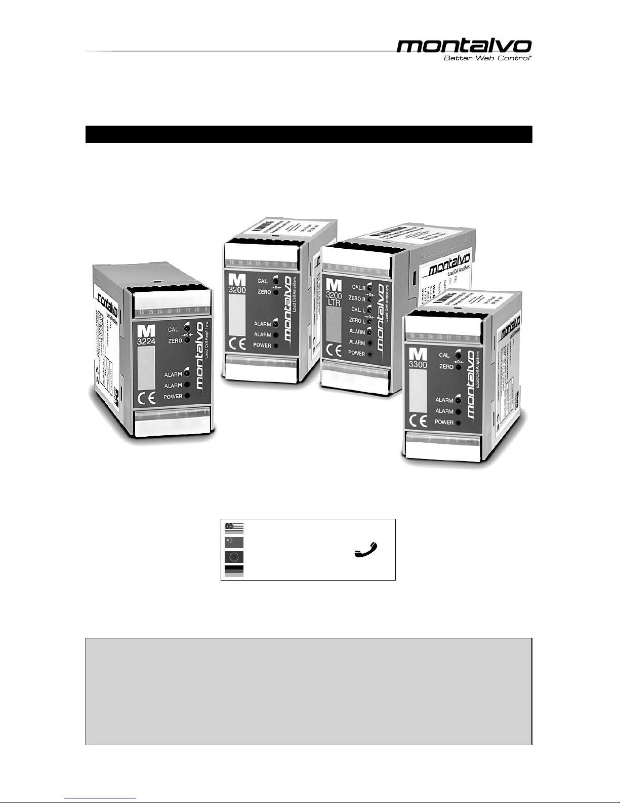
TECHNICAL MANUAL
M Series Ampli er Modules
For Models M3200, M3224, M3200LTR and M3300
Publication Date: 04/22/2019
EST
.
1947
p. 2
M Series Ampli er
__ ___________________________________________________________________________________
Technical Manual
INDEX
www.montalvo.com / Technical details subject to change without notice. Mamp-technical manual-US-07 © Montalvo
Con guration
DIP Switches ............................................................................................3
Fuses ........................................................................................................3
DIP Switch / Fuse Location .......................................................................3
Wiring
M3200 ......................................................................................................4
M3224 ......................................................................................................6
M3200LTR ................................................................................................8
M3300 ....................................................................................................10
Calibration
Zero Point ...............................................................................................12
Calibration ...............................................................................................12
Alarm Level Adjustment .................................................................................13
Speci cations
Technical Data .........................................................................................14
M
3200
1 : Line L
2 :
3 : Line N
4 :
5 : Ground PE
6 : Ground
7 : NC.
8 : NC.
9 : +2.5V Supply
10 : + input +/- 250 mV
11 : - input +/- 250 mV
12 : -2.5V Supply
13 : Total output 0-10V / 0-100μA
14 : Total output 4-20mA / 0-20mA / 0-10V
15 : Ground (0VDC)
16 : Alarm output
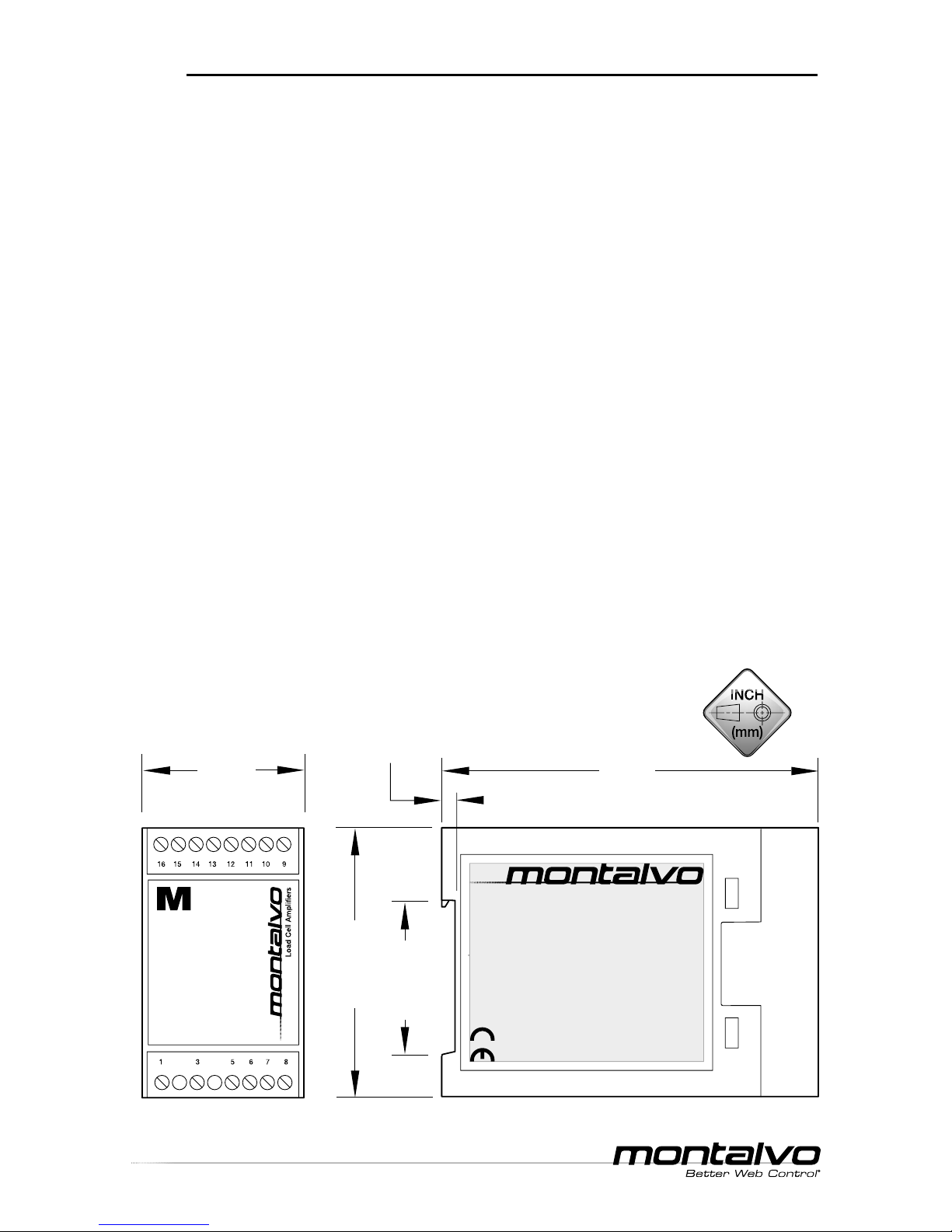
2.95 (75)
4.13
(105)
1.77
(45)
1.42 (36)
0.16 (4)
Load Cell Ampliers
M
Dimensions
EST
.
1947
M Series Ampli er
__ ___________________________________________________________________________________
Technical Manual
p. 3
www.montalvo.com / Technical details subject to change without notice. Mamp-technical manual-US-07 © Montalvo
CONFIGURATION
Model
DIP Switch Settings
Output
Terminal
Affected
1**2**3456
3200
3224
3200LTR
M3300
--ON* ---
Total
0-10V*
13
- - OFF - - - 0-100A
---OFF* ON* OFF* 4-20mA*
14- - - ON OFF OFF 0-20mA
- - - ON OFF ON 0-10V
3200LTR
- ON* ----
Left
0-10V*
7
-OFF---- 0-100A
ON* -----
Right
0-10V*
8
OFF----- 0-100A
DIP Switches
Fuses
The M3200, M3200LTR and M3300 ship from the factory with fuses NOT
installed. Install the appropriate supplied fuse to match the voltage being used.
The M3224 has a resettable fuse to match the required 24V power supply.
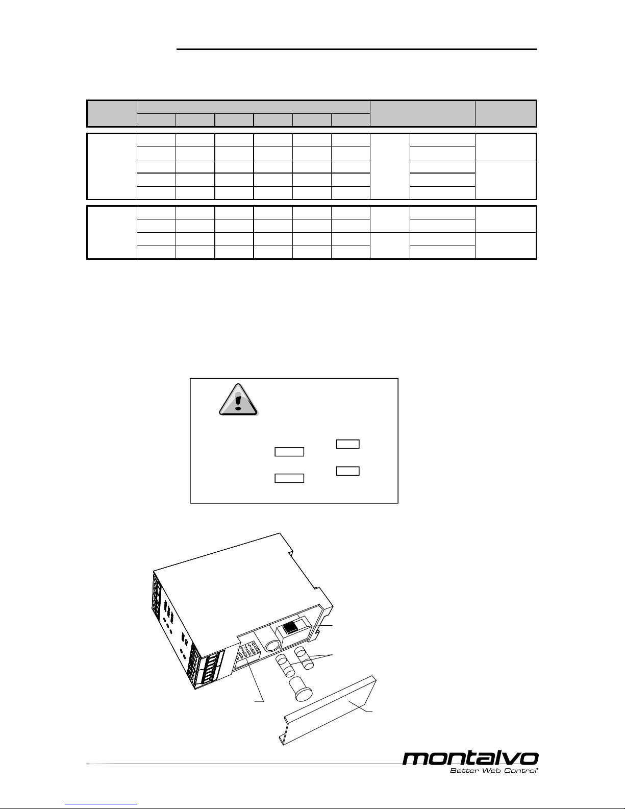
DIP Switch / Fuse Location
* Indicates factory setting.
** DIP switches 1 and 2 have no affect on M3200 and M3224.
This module must be set up for the actual supply voltage.
If power supply is 115V
Step 1 Set power selector in position 115V
Step 2 Mount fuse 80mA T
If power supply is 230V
Step 1 Set power selector in position 230V
Step 2 Mount fuse 50mA T
Note: Power selector and fuses are
found under cover on top of module.
Caution
Failure to follow instructions
may result in equipment
damage or personal injury.
Montalvo
M3200/M3300
Amplier Modules
230
DIP Switches
(1 thru 6)
POWER Switch (AC units only)
(115V or 230V - factory set to 230V)
Cover
(Fuse NOT installed on new units must be installed before operation)
FUSES (AC units only)
(115V or 230V - ships with both)

EST
.
1947
p. 4
M Series Ampli er
__ ___________________________________________________________________________________
Technical Manual
www.montalvo.com / Technical details subject to change without notice. Mamp-technical manual-US-07 © Montalvo
WIRING
M3200 Overview
M3200 Dip Switch Factory Settings
Line L (1)
Line N (3)
Total Output 0-10V / 0-100µA (13)
Total Output 4-20mA / 0-20mA / 0-10V (14)
Ground (0V DC) (15)
Alarm Output (16)
(8) No Connection
(7) No Connection
(6) Ground
(5) Ground PE
(12) - 2.5V Supply
(11) - Input ± 250mV
(10) + Input ± 250mV
(9) + 2.5V Supply (excitation)
16 15
14
13 12
11
10
9
1
3
5
6
7
8
123456
y
ON
See Con guration section (p.3)
for optional DIP switch settings.
EST
.
1947
M Series Ampli er
__ ___________________________________________________________________________________
Technical Manual
p. 5
www.montalvo.com / Technical details subject to change without notice. Mamp-technical manual-US-07 © Montalvo
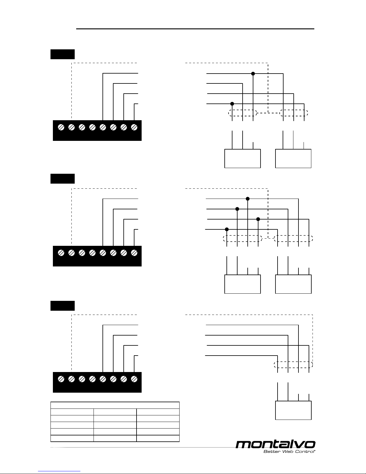
WIRING
(15) Ground (0V DC)
(12) - 2.5V Supply (excitation)
(11) - Input ± 250mV (signal)
(10) + Input ± 250mV (signal)
(9) + 2.5V Supply (excitation)
BK WH BN
or
RD
16 15
14
13 12
11
10
9
BK WH BN
or
RD
#1
Load Cell
#2
Load Cell
(15) Ground (0V DC)
(12) - 2.5V Supply (excitation)
(11) - Input ± 250mV (signal)
(10) + Input ± 250mV (signal)
(9) + 2.5V Supply (excitation)
BK WH BN
or
RD
BL
or
GN
16 15
14
13 12
11
10
9
#1
Load Cell
BK WH BN
or
RD
BL
or
GN
#2
Load Cell
(15) Ground (0V DC)
(12) - 2.5V Supply (excitation)
(11) - Input ± 250mV (signal)
(10) + Input ± 250mV (signal)
(9) + 2.5V Supply (excitation)
16 15
14
13 12
11
10
9
BK WH BN
or
RD
BL
or
GN
Load Cell
* If using only a single half bridge load cell,
connect as shown for #2 load cell.
M3200 Dual Full Bridge Semiconductor Strain Gauge Load Cells
M3200 Single Full Bridge Semiconductor Strain Gauge Load Cell
Standard conductor colors for Montalvo load cell cables
4 pin connector 6 pin connector 3 pin connector
Brown (BN) Red (RD) Red (RD)
White (WH) White (WH) White (WH)
Black (BK) Black (BK) Black (BK)
Blue (BU) Green (GN) NA
M3200 Dual* Half Bridge Semiconductor Strain Gauge Load Cells
 Loading...