

MONTAGUE E36W36, E236W36, E43W36, E243W36, E136W36 Instructional Manual
...
INSTRUCTIONAL
MANUAL
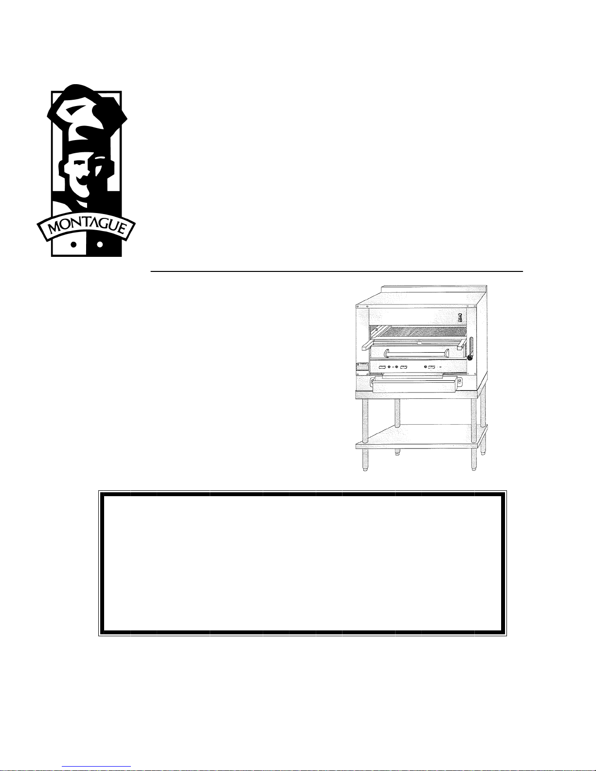
GAS FIRED BROILERS
E36W36 E236W36
E43W36 E243W36
E136W36 EC36
EV136W36 EC45
EC36W36 EV136C36
WC43W36 EV136C45
E136C36 W136XC36
E136C45 W136XC45
with optional searing plate (-SHB)
This manual is prepared for the use of Service Technicians
and should not be used by those not properly qualified. This
manual is not intended to be all encompassing. You should
read, in its entirety, the repair procedure you wish to per-
form to determine if you have the necessary tools,
instruments, and skills required to perform the procedure.
RETAIN THIS MANUAL FOR FUTURE REFERENCE.
DESTINATION COUNTRIES: AUSTRALIA, NEW ZEALAND
THE MONTAGUE COMPANY www.montaguecompany.com
1830 Stearman Avenue • P.O. BOX 4954 • HAYWARD,CA 94540-4954 •TEL: 510/785-8822 • FAX: 510/785-3342
NOTICE:
IMPORTANT FOR YOUR SAFETY
THE INSTALLATION INSTRUCTIONS CONTAINED HEREIN ARE FOR THE USE OF
QUALIFIED INSTALLATION AND SERVICE PERSONNEL ONLY. INSTALLATION OR
SERVICE BY OTHER THAN QUALIFIED PERSONNEL MAY RESULT IN DAMAGE TO THE
UNIT AND/OR INJURY TO THE OPERATOR.
IF YOU SMELL GAS
1. TURN OFF THE APPLIANCE AT THE GAS INLET COCK AND OPEN ALL DOORS
AND WINDOWS.
2. DO NOT OPERATE ANY ELECTRICAL SWITCHES AND EXTINGUISH ALL NAKED
FLAMES.
3. CONTACT THE LOCAL GAS AUTHORITY IMMEDIATELY.
THE FOLLOWING INSTRUCTIONS SHOULD BE READ CAREFULLY AS THE
MANUFACTURER CANNOT BE HELD RESPONSIBLE FOR ANY DAMAGE TO
PROPERTY, PERSONS OR ANIMALS CAUSED BY INCORRECT INSTALLATION OR
OPERATION OF THE APPLIANCE.
POST IN A PROMINENT LOCATION THE INSTRUCTIONS TO BE FOLLOWED IN THE EVENT
THE SMELL OF GAS IS DETECTED. THIS INFORMATION CAN BE OBTAINED FROM THE
LOCAL GAS SUPPLIER.
IN THE EVENT OF POWER FAILURE, DO NOT ATTEMPT TO OPERATE THIS DEVICE.
IMPORTANT
IN THE EVENT A GAS ODOR IS DETECTED, SHUT DOWN UNITS AT MAIN SHUTOFF
VALVE AND CONTACT THE LOCAL GAS COMPANY OR SUPPLIER FOR SERVICE.
FOR YOUR SAFETY
DO NOT SPRAY AEROSOLS, STORE OR USE GASOLINE OR OTHER FLAMMABLE
VAPORS OR LIQUIDS IN THE VICINITY OF THIS APPLIANCE WHILE IN OPERATION.
WARNING!
Improper installation, adjustment, alteration, service, or maintenance can cause
property damage, injury, or death. Read the INSTALLATION AND OPERATING
INSTRUCTIONS thoroughly before installing, servicing, or operating this equipment.
SAVE THESE INSTRUCTIONS FOR FUTURE USE.
2

TABLE OF CONTENTS
IMPORTANT FOR YOUR SAFETY ………. 2
INTRODUCTION ………. 4
GENERAL ………. 4
MODELS ………. 4
DATA PLATE LOCATION ………. 4
SERIAL NUMBER LOCATION ………. 4
RECEIVING AND INSPECTING THE EQUIPMENT
SPECIFICATIONS ………. 5
INSTALLATION ………. 6
STATUTORY REGULATIONS ………. 6
CLEARANCES ………. 6
VENTILATING HOOD ………. 6
VENTILATION AIR ………. 6
ASSEMBLY ………. 6
Legs ………. 6
ELECTRICAL CONNECTION 7
Ceramic Radiants ………. 8
LOCATION ………. 8
SITING ………. 8
BATTERY ARRANGEMENT ………. 8
Setting in Place ………. 8
Floor Mounted Ranges ………. 9
GAS SUPPLY ………. 9
GAS CONNECTION ………. 9
GAS PRESSURE REGULATOR ………. 10
Adjustment Procedure ………. 11
PILOT INITIAL ADJUSTMENT ………. 12
BURNER ADJUSTMENT ………. 12
OPERATION ………. 15
GENERAL ………. 15
OPERATING CONTROLS ………. 16
Gas Control ………. 15
Lighting/Relighting Pilot and Main Burner ………. 15
Shutdown ………. 16
Grid Height Adjustment ………. 16
GENERAL MAINTENANCE ………. 18
GENERAL CLEANING ………. 18
Daily ………. 18
PAINTED SURFACES ………. 18
Exterior ………. 18
Interior ………. 18
STAINLESS STEEL SURFACES ………. 18
VENTILATION ………. 19
SERVICING ………. 19
SAFETY ………. 19
………. 4
C36 & C45 EXPLODED VIEW ………. 20
C36 & C45 PARTS LIST ………. 21
36W36 & 43W36 EXPLODED VIEW ………. 22
36W36 & 43W36 PARTS LIST ………. 23
Montague E136 Series Heavy Duty Range Parts
List
PARTS REMOVAL AND REPLACEMENT PROCEDURES
COVERS AND PANELS ………. 27
Venturi Cover ………. 27
Control Panel Cover ………. 27
DRIP DEFLECTOR ………. 28
PILOT ASSEMBLY AND INJECTOR ………. 29
MAIN BURNER ………. 30
Burner Assembly, Orifice, and Venturi ………. 31
Burner Valve Removal/Replacement ………. 31
CARRIAGE POSITION HANDLE ………. 32
Black Ball Knob ………. 32
Chrome Sleeve ………. 32
Threaded Stud ………. 32
Gear and Tube Assembly ………. 32
Compression Spring ………. 33
Gear with Bracket ………. 33
SERVICE AND ADJUSTMENT PROCEDURES ………. 33
GAS PRESSURE REGULATOR ADJUSTMENT PROCEDURE
PILOT BURNER CLEANING AND ADJUSTMENT PROCEDURE
GAS TAPS ………. 34
CLEANING BURNER HEADS ………. 34
CLEANING BURNER VENTURI ………. 34
CARRIAGE POSITION HANDLE
ADJUSTMENT PROCEDURE
Handle Tension Adjustment ………. 34
CARRIAGE TENSION SPRING ADJUSTMENT
PROCEDURE
MISCELLANEOUS ………. 35
SAFETY AND PILOT BURNER INSPECTION ………. 36
SAFETY PILOT VALVE ………. 36
OVEN PILOT BURNER ………. 36
OPERATIONAL DIFFICULTIES & PROBABLE
CAUSES
TROUBLESHOOTING CHART ………. 38
EC36 & E45 EXPLODED VIEW ………. 39
EC36 & E45 PARTS LIST ………. 40
E36W36 & E43W36 EXPLODED VIEW ………. 42
E36W36 & E43W36 PARTS LIST ………. 43
Montague E136 Series Heavy Duty Range Parts
List
………. 24
………. 27
………. 33
………. 34
………. 34
………. 35
………. 37
………. 46
3
INTRODUCTION
GENERAL
The gas broilers covered in this manual are
manufactured for use with the type of gas indicated
on the nameplate. Some models include a cabinet,
conventional oven or convection oven. Ovens are
covered in separate manuals. This manual only
covers the broiler.
Montague gas broilers are produced with the best
possible material and workmanship. Proper
installation is essential for safe, efficient, troublefree operation.
MODELS
MODEL CONSISTS OF
E36W36
E43W36
EV136W36
E136W36
Cabinet Base Broiler with
Warming Oven
Broiler with Conv. or Std.
Oven + Warming Oven
(opt. ‗W45)
EV136C36
E136C36
E136XC36 Broiler w/ Low Oven (opt.
Broiler with Convection or
Standard Oven (opt. ‗C45)
‗C45)
E236W36 Double Broiler (opt.
EC36 Broiler w/ Stand (opt.
E243W36)
EC45)
EC36W36 Double Broiler + Warming
Oven
EC45W36 Double Broiler + Warming
Oven
Note: A suffix of ―SHB‖ designates searing plate
option.
DATA PLATE LOCATION
The Data Plate is located on the front of the unit,
or inside the oven burner.
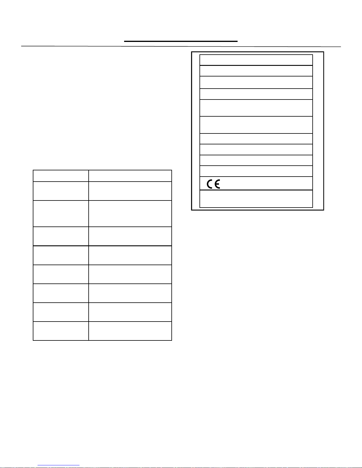
SERIAL NUMBER LOCATION
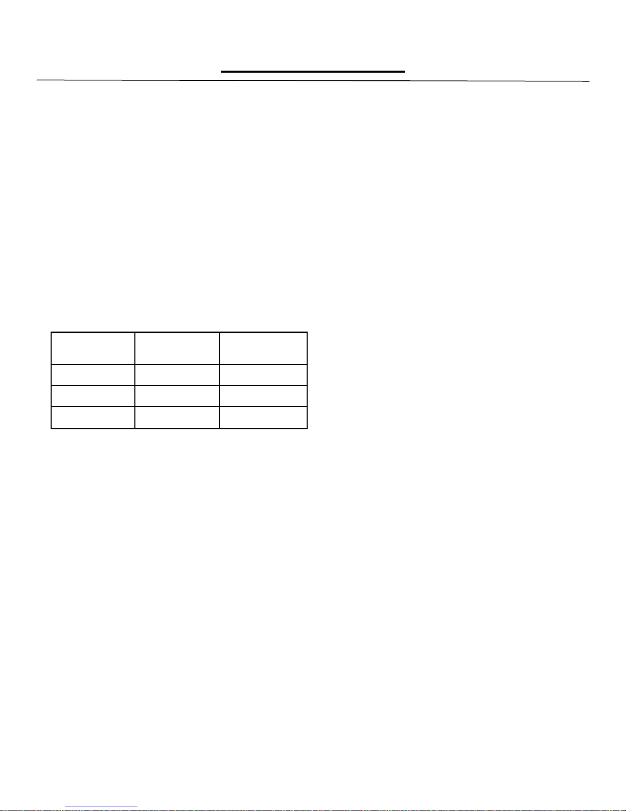
Always have the serial number of your unit available when calling for parts or service. The serial
number is on the nameplate that also includes the
model number. A typical identification plate is
shown in Figure 1.
MODEL:
SERIAL NO.:
HEAT INPUT: kW
CATEGORY:
SUPPLY PRESSURE: mbar
GAS: SET PRESS: mbar
ELECTRICAL
V Hz Ph W
COUNTRY:
P.I.N:
GAS CATERING EQUIPMENT
SALAMANDER– TYPE A
0359-10
THE MONTAGUE COMPANY
HAYWARD, CALIFORNIA USA
Figure 1. Typical Nameplate
RECEIVING AND INSPECTING
THE EQUIPMENT
Care should be taken during unloading so the
equipment is not damaged while being moved
into the building.
1. Visually inspect the exterior of the package and
skid or container. Any damage should be noted and
reported to the delivering carrier immediately.
2. If damaged, open and inspect the contents with
the carrier.
3. In the event that the exterior is not damaged, yet
upon opening, there is concealed damage to the
equipment, notify the carrier. Notification should be
made verbally as well as in written form.
4. Request an inspection by the shipping company
of the damaged equipment. This should be done
within 10 days from receipt of the equipment.
5. Freight carriers can supply the necessary
damage forms upon request.
6. Retain all shipping materials until an inspection
has been made or waived.
4
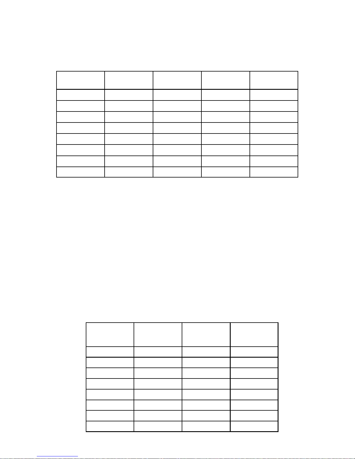
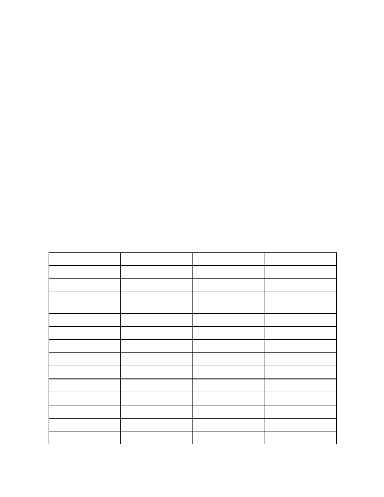
SPECIFICATIONS
Table A: Heat Input
MODEL No. Burners
(broiler/oven)
E36W36 2 / 0 44.3 ea. 44.3 ea. 88.6
Natural Gas
MJ/h
Propane Gas
MJ/h
TOTAL
MJ/h
E43W36 3 / 0 44.3 ea. 44.3 ea. 132.9
E136W36 2 / 1 44.3 / 42.2 ea. 44.3 / 42.2 ea. 130.8
EV136W36 2 / 1 44.3 / 42.2 ea. 44.3 / 42.2 ea. 130.8
E236W36 4 / 0 44.3 ea. 44.3 ea. 177.2
E243W36 6 / 0 44.3 ea. 44.3 ea. 265.8
EC36 2 / 0 44.3 ea. 44.3 ea. 88.6
EC45 3 / 0 44.3 ea. 44.3 ea. 132.9
Table B: Setting Pressure/Injector Size
Manifold Pressure Orifices
Fixed for specified gas type
Natural: 1.0kPa Natural: Broiler: 3.05mm Oven: 2.95mm
Propane: 2.75 kPa Propane: Broiler: 1.93mm Oven: 1.85mm
Gas Inlet Size:
3/4‖ NPT at lower left rear
(all models)
NOTE: The pressure must be measured at the pressure test nipple located at the
manifold pipe with the burner lit.
TABLE C: Aeration Shutter/Pilot Flame Settings
Natural Gas
MODEL
E36W36 25 / — 32 / — 12.5
E43W36 25 / — 32 / — 12.5
Broiler/Oven
mm
Propane
Broiler/Oven
mm
PILOT FLAME
LENGTH mm
E136W36 25 / 19 32 / 22 12.5
EV136W36 25 / 19 32 / 22 12.5
E236W36 25 / — 32 / — 12.5
E243W36 25 / — 32 / — 12.5
EC36 25 / — 32 / — 12.5
EC45 25 / — 32 / — 12.5
5
INSTALLATION
THIS APPLIANCE, WHEN INSTALLED, MUST BE ELECTRICALLY GROUNDED IN ACCORDANCE WITH
LOCAL CODES. THIS APPLIANCE MUST BE INSTALLED WITH THE REQUIREMENTS OF AS5601 / AG601,
LOCAL AUTHORITY, GAS, ELECTRICITY AND ANY OTHER RELEVANT STATUTORY REGULATIONS.
CAUTION: Provision must be made to assure
adequate air supply to unit for proper burner
operation.
STATUTORY REGULATIONS
The installation of this appliance must be carried out
by a competent person in accordance with the relevant regulations, standards, codes of practice, and
the related publications of the country of destination.
CLEARANCES
The following are minimum clearances from combustible and noncombustible materials.
Location Combustible
Construction
Noncombustible
Construction
Back Wall 152 mm 0 mm
Left Side 152 mm 0 mm
Right Side 152 mm 0 mm
1000mm clearance above to combustibles.
With 152mm legs: Suitable for installation on
combustible floors.
Without legs: For use with special insulated base
on noncombustible floors only.
The EV 136 must have an air space behind it.
VENTILATING HOOD
The broiler(s) must be installed under a properly
designed ventilating hood. The hood should extend
at least 152mm beyond all sides of the unit. The
hood should be connected to an adequate mechanical exhaust system.
VENTILATION AIR
The following notes are intended to give general
guidance. For detailed recommendations, refer to
the applicable code(s) in the country of destination.
NOTE 1: The room containing the appliance is
required to have a permanent air vent. The
minimum effective area of the vent is related to the
maximum rated hear input of the appliance and
shall be 4.5 cm² per kW in excess of 7kW.
NOTE 2: Air vents should be of such a size to
compensate for the effects of any extract fan in the
premises.
It is also necessary that sufficient room air ingress
be allowed to compensate for the amount of air
removed by the ventilating system. Otherwise, a
subnormal atmospheric pressure will occur which
may interfere with burner performance or may
extinguish the pilot flame. In case of unsatisfactory
broiler performance, check with the exhaust fan in
the ―OFF‖ position.
This appliance is to be installed with sufficient ventilation to prevent the occurrence of unacceptable
concentrations of substances harmful to health in
the room in which it is installed.
ASSEMBLY
Uncrate broiler as near to final location as possible.
For easier and lighter handling of broiler, remove
grids, grid frame, drip tray and grease container.
Remove all packing materials and accessories from
broiler interior.
Legs
Some broilers are mounted on legs.
1. Screws the legs into the modular stand.
2. Tightly screw the complete leg assembly into
the mounting holes in the bottom of the broiler at
each corner. If the unit is intended for curb
installation, no legs are provided. The curb must
be noncombustible material.
THE GAS CONNECTION IS LOCATED 813mm ABOVE THE FINISHED FLOOR AND 127mm FROM THE LEFT SIDE ON THE
REAR OF THE UNIT
6
Electrical Connection
A terminal block is provided for 208-240 VAC equipment. The wiring diagram is located on the
back of the range. To connect supply wires, remove cover from connection box at right rear of
range. Route supply wires and ground wire through hole with strain relief fitting at top of connection
box. Attach supply wires to proper terminal of terminal block. Attach ground wire to ground loug inside connection box. See wiring diagram for proper connection.
THIS APPLIANCE, WHEN INSTALLED, MUST BE ELECTRICALLY GROUNDED IN
ACCORDANCE WITH LOCAL CODES. THIS APPLIANCE MUST BE INSTALLED WITH THE
REQUIREMENTS OF AS5601 / AG601, LOCAL AUTHORITY, GAS, ELECTRICITY, AND ANY
OTHER RELEVANT STATUTORY REGULATIONS.
THE ELECTRICAL CONNECTION IS LOCATED 254mm ABOVE THE FINISHED FLOOR AND
305mm FROM THE RIGHT SIDE ON THE REAR OF THE UNIT.
The installation of electrical wiring from the electric meter, main control box, or service outlet to the
electric appliance must be performed by a licensed electrician. Qualified installation personnel
must be experienced with such work, be familiar with all precautions required and have complied
with all requirements of state or local authorities having jurisdiction.
OVERALL DIMENSIONS (in millimetres):
Model Height Width Depth
E36W36 1816 914 933
E43W36 1816 1143 933
E(V)136W36 1816 914 933
E(V)136C36 1451 914 933
E(V)136C45 1451 1143 933
E136XC36(SHB) 1426 914 870
E136XC45(SHB) 1426 1143 870
E236W36 1603 914 870
E243W36 1603 1143 870
EC36(SHB) 1324 914 870
EC45(SHB) 1324 1143 870
EC36W36 1968 914 864
EC43W36 1968 1143 864
7
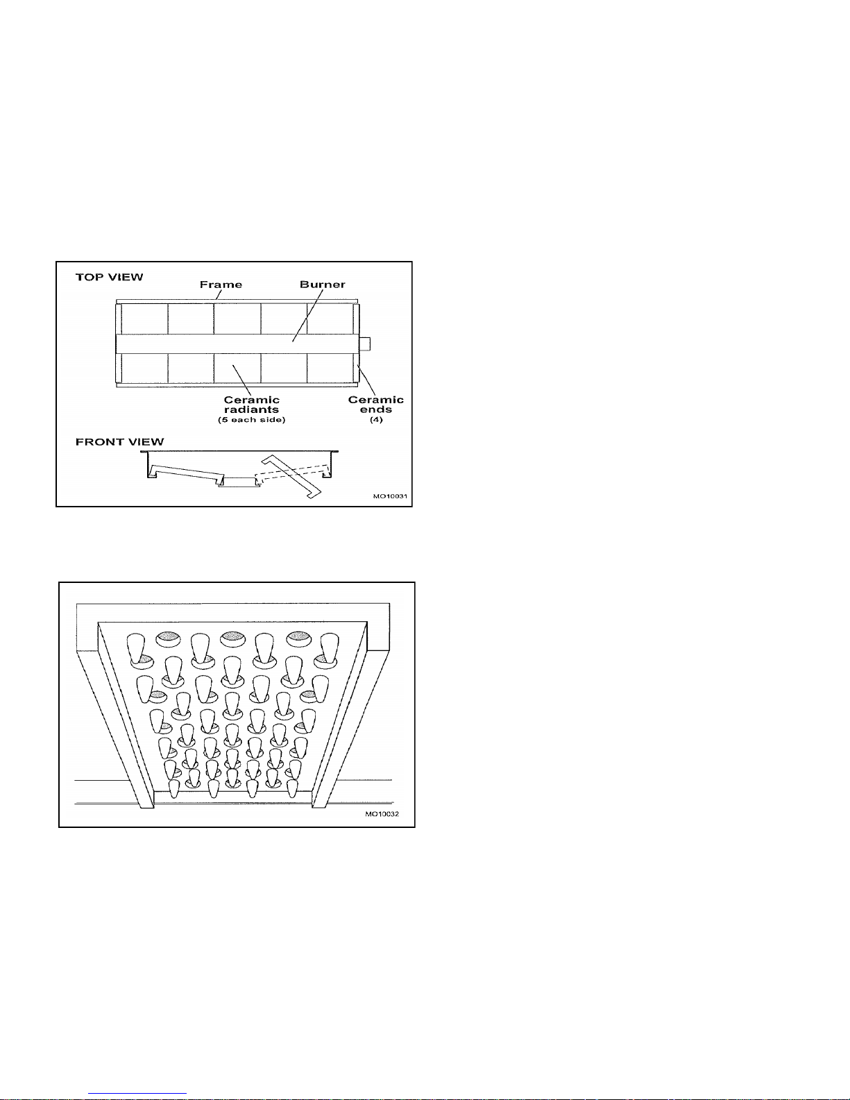
Ceramic Radiants
Ceramic radiants, Figure 2, are located on
each side of the burners. Ceramic end pieces
are installed at both ends of each burner
assembly. Five (5) ceramic radiants are
installed on each side of the burner with the
pointed side facing down and the side holes
facing up, Figure 3.
Figure 2. Ceramic Radiants Positioning
Figure 3. Ceramic Radiants
1. Insert ceramic end pieces at front and rear
of the burner frame. Four (4) are required
for each burner.
2. Tilt ceramic radiants sideways to clear
burner and frame assembly, then lower
radiant into position with one flange resting
on burner ledge and one flange resting on
frame edge.
3. Install the remaining ceramic radiants so
that five (5) ceramic radiants are located on
each side of the burner.
LOCATION
Adequate clearance for service and proper
operation must be provided at the front, top,
sides, and back. The combustion air openings
are provided in the front of the unit and must
not be obstructed.
SITING
The floor on which the range is to be sited must
be capable of adequately supporting the weight
of the appliance and any ancillary equipment.
Once in position, check that the unit is level,
both front to back and side to side. Adjust if
necessary, using the adjusting foot on each
leg.
BATTERY ARRANGEMENT
Carefully remove range from crate. Burner tie
wires and other packing materials must be
removed from the unit. On stainless steel units,
the protective material covering the stainless
steel must be removed immediately after unit is
installed.
Setting in Place
Model Nos. E36W36, E43W36, E136W36 and
EV136W36.
8

Floor Mounted Ranges
1. Place the first unit in the exact position it will
occupy in the battery.
2. Using a carpenter‘s level, level the unit front-
to-rear and side-to-side. AN UNLEVELED UNIT
WILL ADVERSELY AFFECT PERFORMANCE.
Adjust as follows:
FLOOR INSTALLATION ON LEGS: Level by
turning foot on leg.
CURB INSTALLATION: Place shim under the low
side. This operation is important since variations
in floors and curbs are common. Unless units are
level, aligning the gas supply manifold will be
difficult and the units will not fit together tightly.
3. Remove the valve panel from the broiler.
4. Move the next unit into position.
5. Engage union nut on manifold with male fitting
on next unit and draw up union nut hand tight. Be
sure appliances meet together both front and rear.
If manifolds do not align, then units are not level.
In extreme cases, it may be necessary to loosen
manifold bolts and adjust.
6. Continue leveling and connecting gas supply
manifolds together until all appliances in battery
are connected.
7. Tighten manifold gas union. Use backup
wrench to prevent manifold from rotating.
FAILURE TO DO THIS MAY RESULT IN
DAMAGE TO THE PILOTS AND GAS VALVES.
GAS SUPPLY
The local gas region should be consulted at the
installation planning stage in order to establish the
availability of an adequate supply of gas and to
ensure that the meter is adequate for the required
flow rate. The pipe work from the meter to the
appliances must be of appropriate size. Where a
number of appliances are installed in a battery, no
more than five should be served by any one
supply pipe.
All fixed (non-mobile) appliances MUST be fitted
with a manual gas cook upstream of the
appliance to provide a means of isolation for
servicing and cleaning. A union or similar means
of disconnection must be provided between the
gas cook and the appliance.
A manually operable valve must be fitted to the
gas supply to the kitchen to enable it to be isolated in an emergency. Wherever practical, this shall
be located either outside the kitchen or near an
exit in a readily accessible position.
Where it is not practical to do this, an automatic
isolation valve system shall be fitted which can be
operated from a readily accessible position near
the exit.
At locations where the manual isolation valve is
fitted or the automatic system can be reset, a
notice MUST be fitted, stating:
“ALL DOWNSTREAM BURNER AND PILOT
VALVES MUST BE TURNED OFF PRIOR TO
ATTEMPTING TO RESTORE THE SUPPLY.
AFTER EXTENDED SHUT OFF, PURGE
BEFORE RESTORING GAS.”
GAS CONNECTION
Before connecting the broiler(s) to the gas supply
line, be sure that all new piping has been cleaned
and purged to prevent any foreign matter from
being carried into the controls by the gas. In some
cases, filters or drops are recommended. A
separate gas shutoff valve must be installed
upstream from the gas pressure regulator
adjacent to the broiler and located in an
accessible area.
It is important that adequately sized piping be run
directly to the point of connection at the broiler
with as few elbows and tees as possible. Consult
your local gas company for proper piping size and
gas pressure. Each broiler has a 3/4" NPT
manifold input located at the lower left rear of the
broiler, Figure 4. On dual broilers, each broiler
must have a separate regulator.
NOTE: Pipe joint compound or thread sealant
that is used should be resistant to action of
liquefied petroleum gases.
9
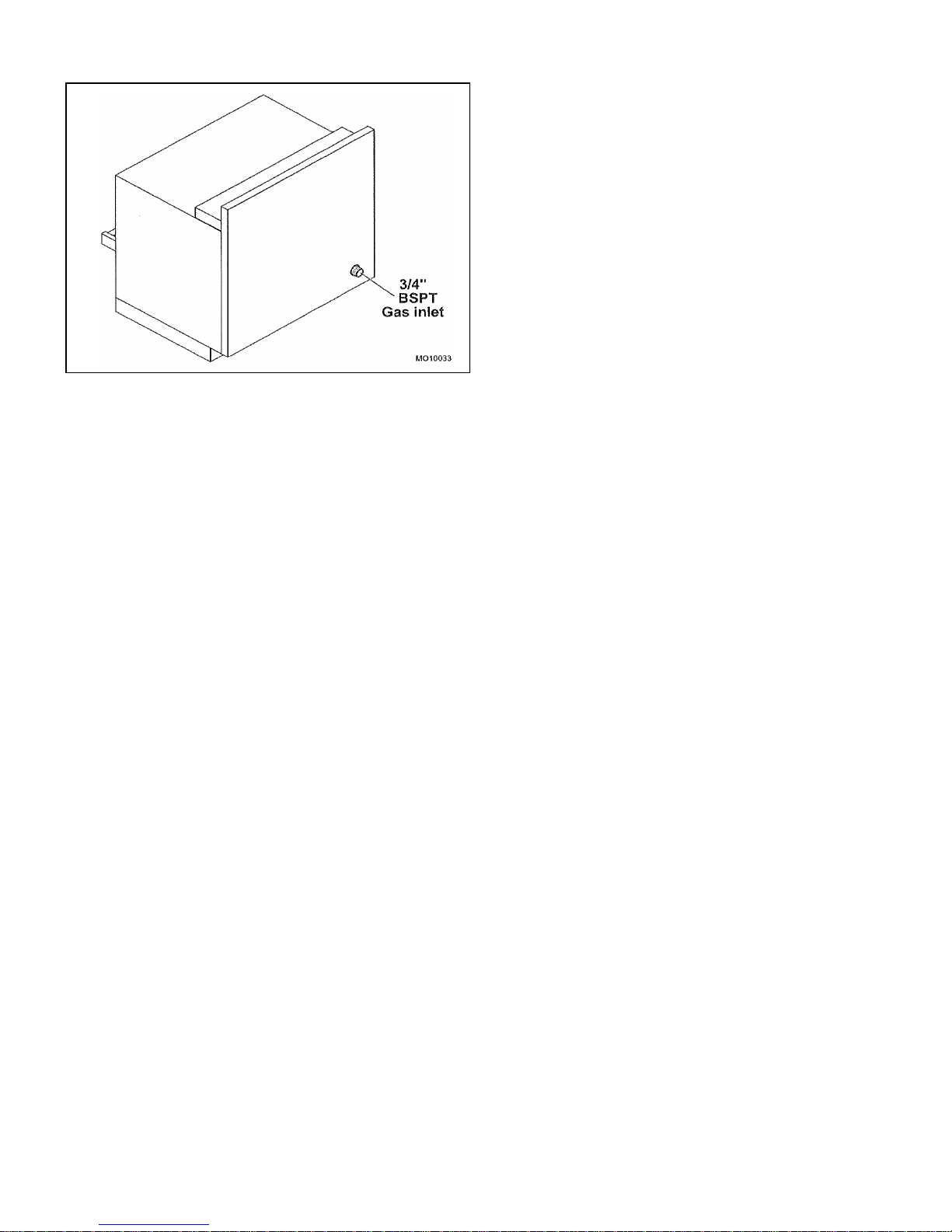
Figure 4. Gas Inlet
Install the gas pressure regulator with gas
flowing as indicated by the arrow on the
regulator. The arrow must be pointing in toward
the unit. Use pipe compound or thread sealant
and carefully thread regulator to pipe so that
there is no cross threading, etc., which could
cause leakage.
1. Apply wrench only to the flat areas around the
pipe tapping at the end being threaded to the
pipe to avoid possible damage to the regulator
body which could result in leakage.
2. Connect the gas supply line from the service
gas shutoff valve to the inlet side of the gas
pressure regulator using 3/4" pipe. Avoid kinks
or sharp bends that could restrict gas flow.
NOTE: If flexible or semi-flexible connectors
are used, an AGA listed flexible connector
with an I.D. equal to 3/4" pipe must be used.
WARNING!
DO NOT USE A DOMESTIC TYPE
FLEXIBLE GAS CONNECTOR.
3. Turn gas shutoff valve on and carefully check
for gas leaks immediately. Do this before
attempting to operate the broiler.
WARNING!
Test all pipe joints for leaks before operating
broiler. This includes all gas connections
that may have loosened during shipment.
Use a rich soap solution (or other accepted
leak tester) around all pipe connections and
all other joints. Do not use an open flame.
Absolutely no leakage should occur,
otherwise there is a danger of fire or
explosion depending upon conditions. Do
not use unit leakage is detected.
After piping has been checked for leaks, all piping receiving gas should be fully purged to remove air.
GAS PRESSURE REGULATOR
WARNING!
THE BROILER(S) IS/ARE DESIGNED FOR
USE WITH A GAS PRESSURE REGULATOR.
THE REGULATOR(S) SUPPLIED WITH THIS
UNIT MUST BE USED.
FOR NATURAL GAS: This gas pressure
regulator is factory adjusted for 1.0 kPa manifold
pressure. The rated inlet pressure to the
regulator is 3.45 kPa.
FOR PROPANE GAS: This gas pressure
regulator is factory adjusted for 2.75 kPa
manifold pressure. The rated inlet pressure to
the regulator is 3.45 kPa.
The broiler is equipped with fixed orifices for use
with a manifold pressure of 1.0 kPa for G20 gas
and 2.75 mbar for propane gas.
Position the gas pressure regulator outside the
broiler as near to the unit as possible.
CAUTION: The gas pressure regulator must
be located out of the heat zone to prevent
damage to the regulator.
The whole of the gas installation, including the
meter, should be inspected, purged, and tested
for soundness in accordance with the codes of
the country of destination.
10
Adjustment Procedure
WARNING!
DO NOT ALLOW UNTRAINED PERSONNEL
TO MAINTAIN OR SERVICE THE GAS
PRESSURE REGULATOR.
1. Before adjusting the regulator, check the
incoming gas line pressure into the regulator.
Incoming pressure must be 20 kPa for natural
gas or 3.5 kPa for propane gas.
2. If incoming pressure is not correct, have the
gas source checked and adjusted.
3. Make sure that the regulator is mounted in
the horizontal position with the arrow pointing
in the direction of the gas flow. SEE PAGE 15,
LIGHTING/RELIGHTING PILOT AND
BURNER.
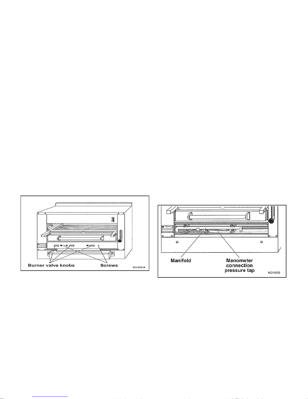
4. Remove the main burner control valve
knobs, Figure 5.
6. Connect a manometer to the pressure tap
provided on the broiler unit gas piping manifold,
Figure 6. Turn all gas taps to the full on ―O‖
position.
7. Check the manometer reading. The
reading must be 1.0 kPa for natural gas or 2.75
kPa for propane gas, per Table B on PAGE 5.
8. If incoming line pressure is not correct,
adjust the regulator. Remove the seal cap
on the top of the regulator.
9. Insert a blade-type screwdriver into the top
hole of the regulator.
10. Turn the adjustment screw clockwise to
increase the pressure, or counter clockwise
to decrease the pressure.
While watching the manometer, turn the
adjustment screw to set proper regulator outlet
pressure to the manifold.
Figure 5. Control Valve Knobs
5. Remove the control valve panel by
removing two screws.
Figure 6. Gas Pressure Tap
11
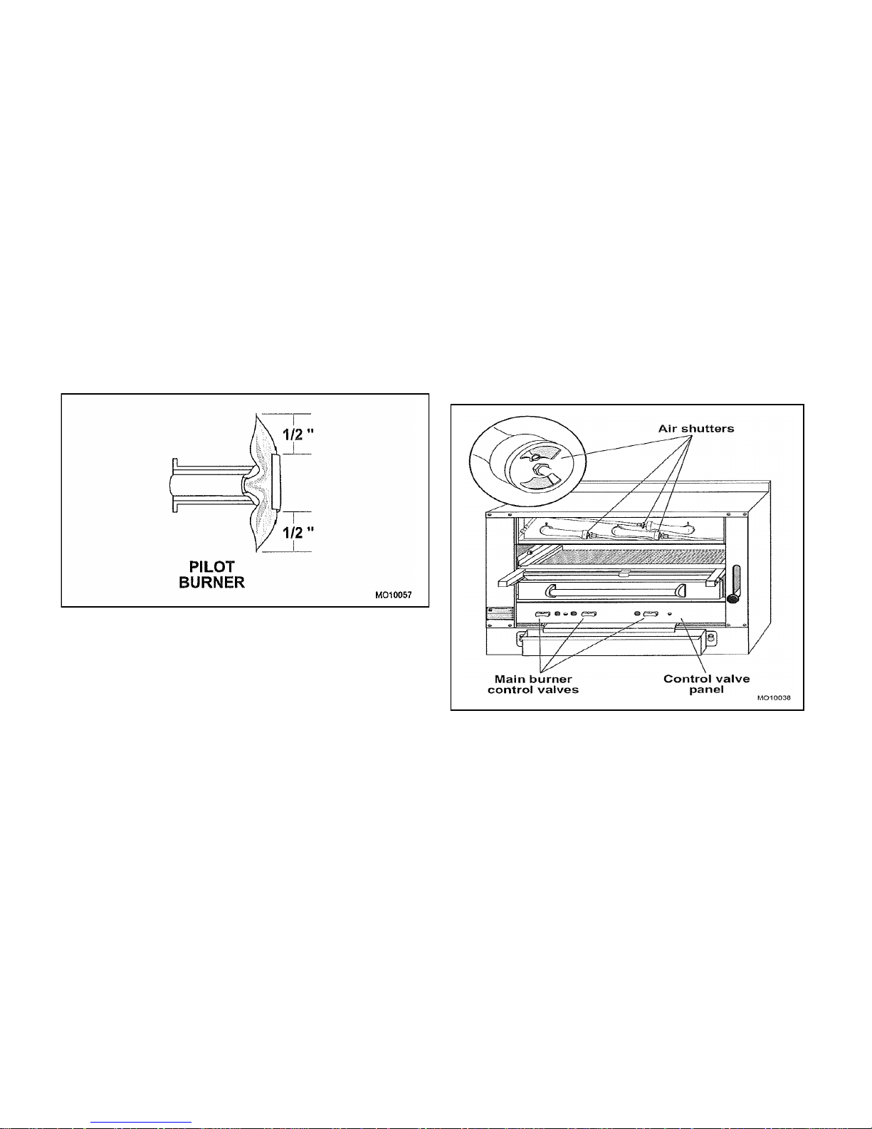
PILOT INITIAL ADJUSTMENT
Each burner has a separate pilot burner. The
pilot flame is adjusted through access holes in
the valve control panel, Figure 7. Pilot access
is through the broiler opening.
1. Turn the main gas shut off valve to the ON
position.
2. Light each pilot.
3. Ensure that each pilot burner has a steady
blue flame, Figure 7, per Table C on PAGE
5. The pilot flame should envelop the tip of
the thermocouple. The pilot flame can be
viewed up through the opening of the broiler
compartment.
1. Lift off the Venturi cover to access the air
shutter for each main burner.
2. Turn on the main burner control valve for
the main burner to be adjusted by rotating
the main burner control valve fully counterclockwise to the ―O‖ position.
3. Increase the air shutter openings until the
flame on the burner begins to ―lift‖. Then
close the shutter until flame no longer
floats, and lock in place. A yellow streaming
flame indicates insufficient air. Correct this
condition by increasing air shutter opening.
The correct setting is shown on Table C on
PAGE 5.
Figure 7. Pilot Burner
Replace the control valve panel and the main
control valve handles.
BURNER ADJUSTMENT
The efficiency of the broiler depends on a
delicate balance between the supply of air and
the volume of gas at each main burner
resulting in complete combustion. Whenever
this balance is disturbed, poor operating
characteristics occur. An air shutter, Figure 8,
on the front of each main burner controls the
air supply.
NOTE: Pilots should be lit, SEE PAGE 12,
before adjusting the main burners.
Figure 8. Main Burner Air Shutter
4. After all main burners are properly adjusted,
reinstall the Venturi cover.
5. Turn all main burner control valves fully
clockwise to the ―O‖ position to turn the
main burner off.
12
OVEN MINIMUM FLAME SETTING
This is the flame that must be maintained on the burner when the oven has come up to the
temperature set on the dial. Enough gas must be bypassed by the control to keep the entire burner
lit. The thermostat regulates the flame from high to low in accordance with the oven temperature
and will automatically turn down to this minimum flame when the temperature set on the dial is
attained in the oven.
1. Light the oven, set thermostat to 100°C and allow 5 minutes for the oven temperature to
stabilize.
2. After oven temperature rises and remains constant, turn dial back to low. This closes the main
valve and permits only the bypass gas to the burner.
3. Remove dial.
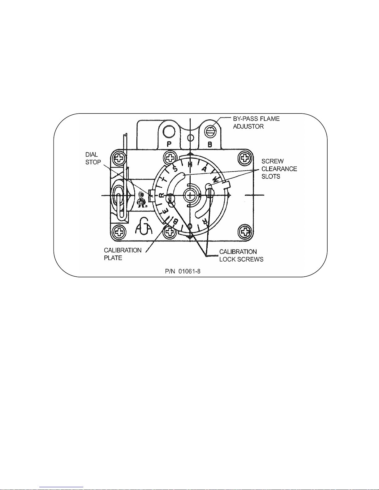
4. With a screwdriver, turn the bypass flame adjustor screw counterclockwise to increase the
bypass flame or clockwise to decrease it until the flame over the entire burner is approximately
4mm high. Replace dial.
13

THERMOSTAT CALIBRATION CHECK
The calibration of this thermostat should not be changed until considerable experience with cooking
results has definitely proved that the thermostat is not maintaining the proper temperature. The
recalibration should not be made until the bypass (minimum burner) flame has been properly
adjusted.
If re-calibration becomes necessary, the following procedure should be followed:
1. Place the thermocouple of test instrument or thermometer in the middle of the oven.
2. Light the main burner.
3. Turn dial to between the ―180‖ and the ―200‖ position (190).
4. Allow the oven to heat until the flames cut down to bypass. After sufficient time, check
temperature. If the temperature does not read within 10 degrees of the dial setting, recalibrate
as follows:
A. Pull dial straight off without turning.
B. Hold calibration plate and loosen the two calibration lock screws until the plate can be
moved independently of the control.
C. Turn calibration plate so that the instrument or thermometer reading is in line with the
indi cator mark. Hold plate and tighten screws firmly. Turn the calibration plate counter
clockwise if the test reading is higher than the dial setting. Replace dial.
NOTE: If the above adjustment is prevented by the two loosened calibration lock screws `
being in contact with the ends of the screw clearance slots in the calibration plate,
remove the screws and after turning the calibration plate to the proper location,
reassemble screws in the other tapped holes designed for them.
OVEN
A. Light pilot in accordance with the Lighting Instructions.
B. Check that the length of the pilot flame is correct per table C.
All pilot flames should envelop the tip of the thermocouple. The pilot flame can be viewed through
the opening in the front of the burner compartment panel.
Replace the burner access panel.
Hand the Instructions & Operation Manual to the user or purchaser for retention and instruct them
in the efficient and safe operation of the appliance.
Tell the user of the location of the gas isolation cock for use in an emergency.
Leave this manual with the user or purchaser.
14
OPERATION
GENERAL
This appliance has been classified as
commercial cooking equipment and must be
operated by qualified and/or professional
operating personnel.
WARNING!
The broiler and its parts are hot. Use care
when operating or servicing the unit.
CAUTION:
Do not obstruct the flow of combustion and
ventilation air to the broiler. Keep appliance
area free and clear of combustibles.
OPERATING CONTROLS
WARNING!
IN THE EVENT GAS ODOR IS DETECTED,
SHUT DOWN UNITS AT MAIN GAS
SHUTOFF VALVE AND CONTACT THE
LOCAL GAS COMPANY OR GAS
SUPPLIER FOR SERVICE.
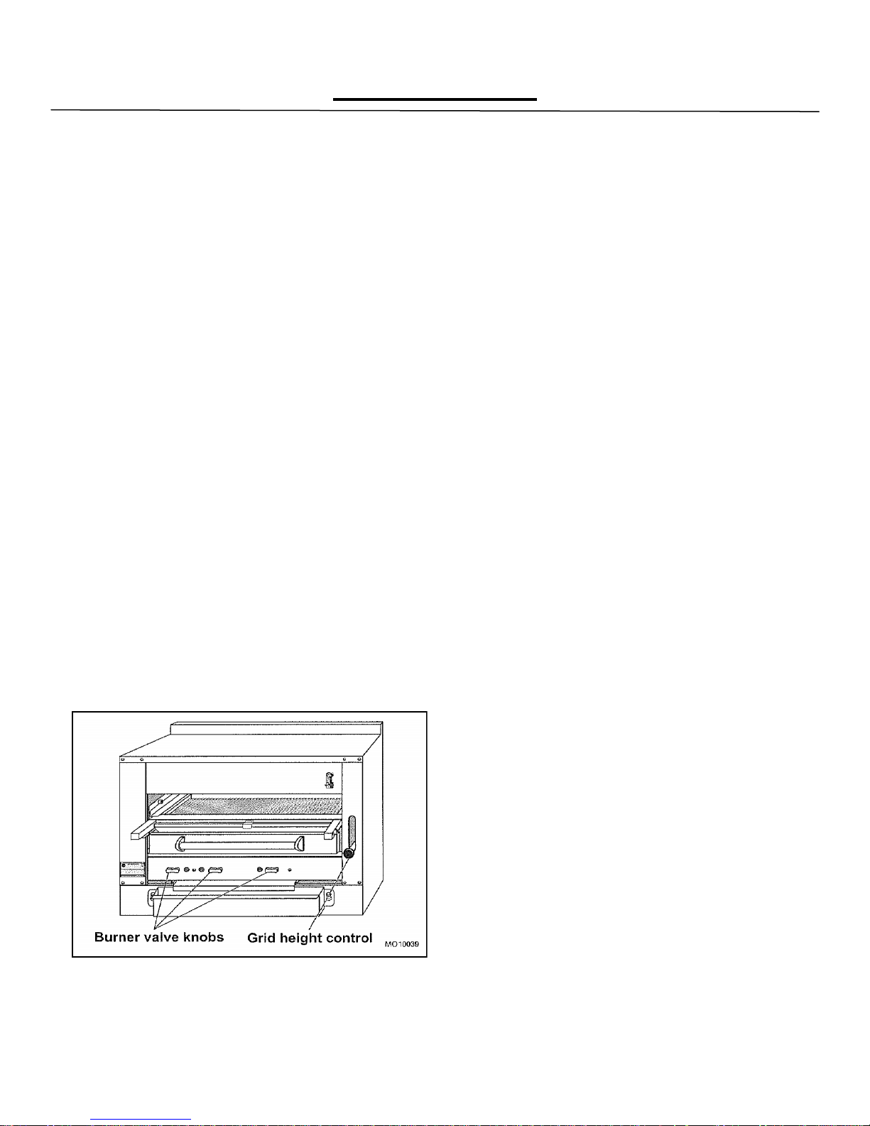
The following controls are used for operation of
the broiler, Figure 9.
BURNER CONTROL: Used to turn the main
burner and pilot gas on or off. One control for
each burner.
GRID HEIGHT: The grid is set to the desired
cooking height by depressing the ball and
adjusting the lever up or down.
Gas Control
Lighting/Relighting Pilot and Main Burner
1. Turn burner valve handle to off position and
wait five (5) minutes.
2. Push in the tap and turn it counter-
clockwise to the ignition position.
3. Holding the tap fully in, light the pilot with a
match or taper.
4. When the pilot is lit, continue to hold the tap
in for 20 seconds, then release it. If the pilot
goes out, wait for five (5) minutes, then
repeat from step 1.
5. When the pilot is established, push the tap
in again and turn it counter-clockwise to the
full flame position, thus lighting the main
burner.
6. If pilot becomes extinguished, turn main
burner valve to the off position (fully counterclockwise) and wait five (5) minutes
before relighting.
Figure 9. Operating Controls
15
 Loading...