

MONTAGUE 36W36, 235W36, 43W36, 243W36, 136W36 Parts Manual
...
SERVICE & P ARTS MANUAL
GAS FIRED
BROILERS
36W36 235W36
43W36 243W36
136W36 C36
V136W36 C45
I
G
S
E
N
D
THE M
ONTAGUE CO.
C
E
D
R
E
I
T
I
F
NOTICE
This manual is prepared for the use of Service Technicians
and should not be used by those not properly qualified.
This manual is not intended to be all encompassing. You
should read, in its entirety, the repair procedure you wish
to perform to determine if you have the necessary tools,
instruments and skills required to perform the procedure.
RETAIN THIS MANUAL FOR FUTURE REFERENCE.
The MONTAGUE Company
1830 Stearman A ve. • P.O. Box 4954 • Hayward, CA 94540-4954
T el: 510/785-8822
Fax: 510/786-9931
1-888-875-2722
WWW.MONTAGUECOMPANY.COM
IMPORTANT FOR YOUR SAFETY
THIS MANUAL HAS BEEN PREPARED FOR PERSONNEL QUALIFIED TO INSTALL GAS EQUIPMENT,
WHO SHOULD PERFORM THE INITIAL FIELD START-UP AND ADJUSTMENTS OF THE EQUIPMENT
COVERED BY THIS MANUAL.
Qualified installation personnel are individuals, a firm, corporation, or company which either in person or through a
representative are engaged in and are responsible for:
A. The installation or replacement of gas piping or the connection, installation, repair or servicing of
equipment, who is experienced in such work familiar with all precautions required, and have complied with
all requirement of state or local authorities having jurisdiction. Reference: National Fuel Gas Code, ANSI
Z223.1, section 1.4, latest addenda.
B. The installation of electrical wiring from the electric meter, main control box or service outlet to the electric appliance.
Qualified installation personnel must be experienced in such work, be familiar with all precautions required and have
complied with all requirements of state and local authorities having jurisdiction. Reference: National Electric Code,
ANSI/NFPA No. 70, latest addenda.
THE BROILER(S) MUST BE INSTALLED IN ACCORDANCE WITH LOCAL CODES, OR IN THE ABSENCE OF
LOCAL CODES, WITH THE NATIONAL FUEL GAS CODE, ANSI Z223.1 LATEST ADDENDA, INCLUDING:
The appliance and its individual shutoff valve must be disconnected from the gas supply piping system during
any pressure testing of that system at test pressures in excess of 1/2 psig (3.45 kPa).
The appliance must be isolated from the gas supply piping system by closing its individual manual shutoff valve during
any pressure testing of the gas supply piping system at test pressures equal to or less than 1/2 psig (3.45 kPa).
POST IN A PROMINENT LOCATION THE INSTRUCTIONS TO BE FOLLOWED IN THE
EVENT THE SMELL OF GAS IS DETECTED. THIS INFORMATION CAN BE OBTAINED
FROM THE LOCAL GAS SUPPLIER.
IN THE EVENT OF A POWER FAILURE, DO NOT ATTEMPT TO OPERATE THIS DEVICE.
IMPORTANT
IN THE EVENT A GAS ODOR IS DETECTED, SHUT DOWN UNITS AT MAIN SHUTOFF
VALVE AND CONTACT THE LOCAL GAS COMPANY OR GAS
SUPPLIER FOR SERVICE.
FOR YOUR SAFETY
DO NOT STORE OR USE GASOLINE OR OTHER FLAMMABLE VAPORS OR LIQUIDS IN
THE VICINITY OF THIS OR ANY OTHER APPLIANCE.
WARNING
IMPROPER INSTALLATION, ADJUSTMENT, ALTERATION, SERVICE OR MAINTENANCE
CAN CAUSE PROPERTY DAMAGE, INJURY OR DEATH. READ THE INSTALLATION,
OPERATING AND MAINTENANCE INSTRUCTIONS THOROUGHLY BEFORE INSTALLING,
SERVICING OR OPERATING THIS EQUIPMENT.
SAVE THESE INSTRUCTIONS FOR FUTURE USE.
SM-2
The MONTAGUE Company

TABLE OF CONTENTS
SAFETY PRECAUTIONS .................................................................................................................................2
INTRODUCTION ................................................................................................................................................4
GENERAL...................................................................................................................................................4
Models..................................................................................................................................................4
Installation............................................................................................................................................4
Operation .............................................................................................................................................4
Cleaning ...............................................................................................................................................4
TOOLS ........................................................................................................................................................4
SPECIFICATIONS ...................................................................................................................................... 5
REMOVAL AND REPLACEMENT OF PARTS ................................................................................................6
COVERS AND PANELS ............................................................................................................................ 6
Venturi Cover........................................................................................................................................6
Control Panel Cover .............................................................................................................................6
DRIP DEFLECTOR ..................................................................................................................................... 6
DRIP TRAY AND HORIZONTAL GREASE CONTAINER...........................................................................7
PILOT .......................................................................................................................................................... 7
Adjustment Valve.................................................................................................................................7
Pilot Assembly and Orifice.................................................................................................................. 7
MAIN BURNERS ........................................................................................................................................8
Burner Assembly, Orifice and Venturi.................................................................................................8
Burner Valve.........................................................................................................................................9
CARRIAGE POSITION HANDLE..............................................................................................................10
Black Ball Knob ................................................................................................................................. 10
Chrome Sleeve................................................................................................................................... 10
Threaded Stud.................................................................................................................................... 10
Gear and Tube Assembly .................................................................................................................. 10
Compression Spring .......................................................................................................................... 10
Gear with Bracket ..............................................................................................................................11
SERVICE AND ADJUSTMENT PROCEDURES............................................................................................. 12
GAS PRESSURE REGULATOR ADJUSTMENT PROCEDURE ............................................................. 12
PILOT BURNER ADJUSTMENT PROCEDURE ....................................................................................... 12
CARRIAGE POSITION HANDLE ADJUSTMENT PROCEDURE ............................................................. 13
Handle Tension Adjustment............................................................................................................... 13
CARRIAGE TENSION SPRING ADJUSTMENT PROCEDURE............................................................... 13
TROUBLESHOOTING CHART........................................................................................................................ 14
C36 & C45 EXPLODED VIEW........................................................................................................................ 16
C36 & C45 PARTS LIST ................................................................................................................................. 17
36W36 & 43W36 EXPLODED VIEW.............................................................................................................. 20
36W36 & 43W36 PARTS LIST .......................................................................................................................21
CALIFORNIA REGULATIONS ........................................................................................................................23
GAS FIRED BROILERS
SM-3

INTRODUCTION
GENERAL
Montague Gas Broilers are manufactured for use with
the type of gas indicated on the nameplate (Natural
Gas or Propane).
Models
The following models are covered in this manual:
MODEL CONSISTS OF
36W36 Cabinet-Base Broiler
with Warming Oven
43W36 Cabinet-Base Broiler
with Warming Oven
136W36 Broiler with Conventional Oven and
Warming Oven
V136W36 Broiler with Convection Oven
236W36 Double Broiler
243W36 Double Broiler
C3 6 Broiler Only on Stand
C4 5 Broiler Only on Stand
Installation
Refer to the Installation and Operation Manual.
Operation
Refer to the Installation and Operation Manual.
Cleaning
Refer to the Installation and Operation Manual.
TOOLS
• Standard set of hand tools
• Gas leak detection equipment
• Gas pressure manometer
SM-4
The MONTAGUE Company

SPECIFICATIONS
MODEL
NO. BURNERS NA TURAL GAS PROP ANE GAS TOTAL
(broiler only) BTU/HR BTU/HR BTU/HR
36W36 2 42,000 ea. 42,000 ea. 84,000
43W36 3 42,000 ea. 42,000 ea. 126,000
136W36 2 42,000 ea. 42,000 ea. 124,000
V136W36 2 42,000 ea. 42,000 ea. 129,000
236W36 4 42,000 ea. 42,000 ea. 168,000
243W36 6 42,000 ea. 42,000 ea. 252,000
C36 2 42,000 ea. 42,000 ea. 84,000
C45 3 42,000 ea. 42,000 ea. 126,000
Manifold Pressure
Natural Gas: 6.0" W.C.
Propane Gas: 10.0" W.C.
Orifices
Fixed for specified gas type
Natural Gas: #33 DMS
Propane Gas: #48 DMS
Gas Inlet Size:
3/4" NPT at lower left rear (all models)
GAS FIRED BROILERS
SM-5
PARTS REMOVAL AND REPLACEMENT PROCEDURES
Perform the following procedures to remove and
replace parts. To eliminate mistakes when ordering
parts, always provide the following information:
• Model Number
• Serial Number
These numbers are located on the nameplate.
CAUTION
Turn off the broiler gas valve and allow broiler
to cool before removing any components.
COVERS AND PANELS
CAUTION
Turn off the gas supply at the manual shutoff
valve that is next to the broiler before
attempting to loosen any gas connections.
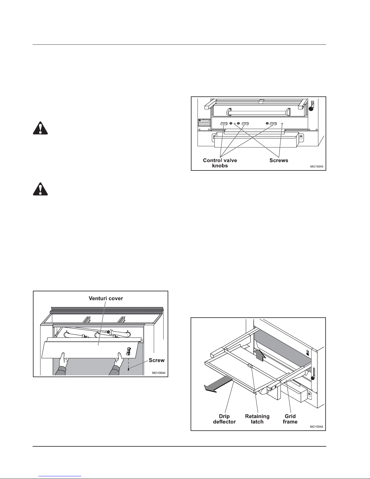
Venturi Cover
Removal of the venturi cover provides access to the air
shutter adjustments and main burner orifices.
1. Remove the two screws under the front edge of
the venturi cover.
2. Lift the venturi cover from the broiler.
1. Turn the control valves to the full off position, then
remove the control valve knobs.
2. Remove the two screws from the front of the
control panel.
Figure 2. Control Panel Cover
DRIP DEFLECTOR
The drip deflector is located below the grid frame and
is angled toward the back of the broiler. Grease
dripping onto the drip deflector runs off the back edge
to the drip tray then flows forward into the horizontal
grease container.
1. Pull the grid frame assembly forward to the stop.
2. Remove the grids from the frame assembly.
3. Lift the back edge of the drip deflector to disengage
the drip deflector from the retaining latch.
4. Slide the drip deflector out at a downward angle.
Figure 1. Venturi Cover
Control Panel Cover
Removal of the control panel cover provides access to
the burner valves, pilot adjustment and carriage springs.
SM-6
5. When reinstalling the drip deflector, be sure to
engage the front end under the retaining latch.
Figure 3. Drip Deflector
The MONTAGUE Company
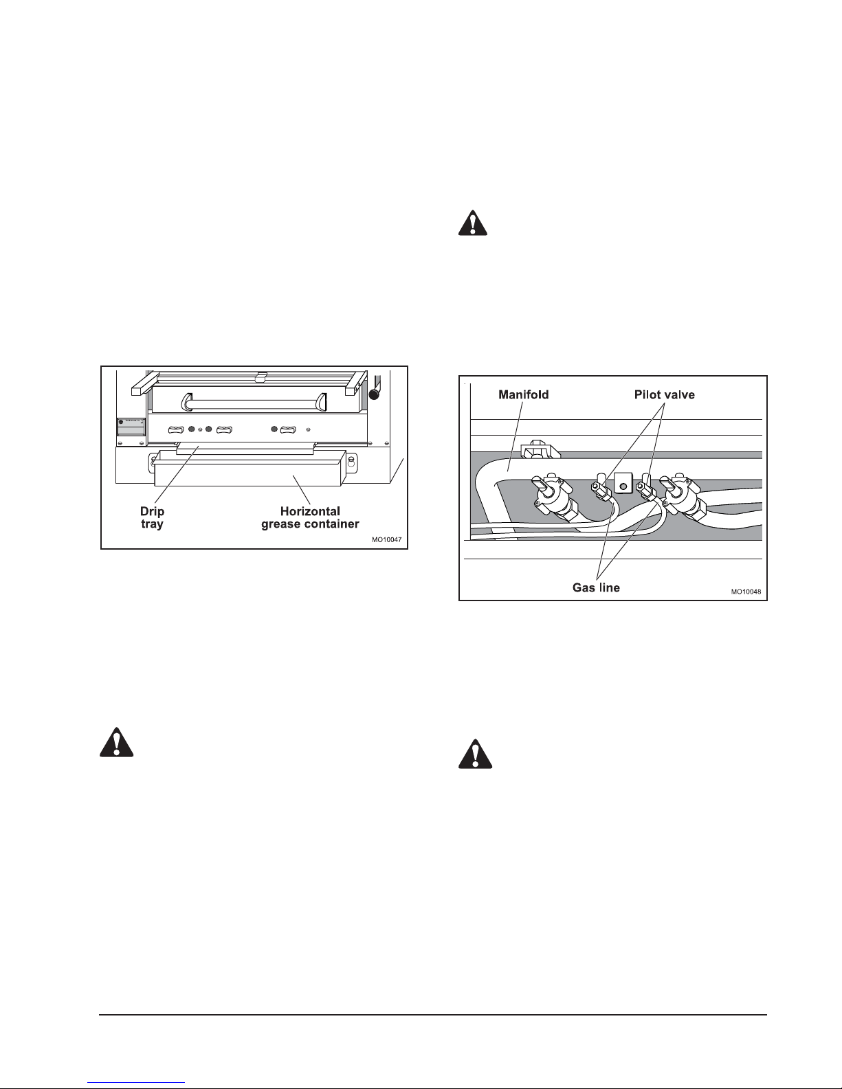
DRIP TRAY AND HORIZONTAL
GREASE CONTAINER.
The drip tray is located below the drip deflector.
Grease dripping onto the drip deflector runs off the
back edge to the drip tray then flows forward into the
horizontal grease container.
1. Pull the drip tray straight out the front of the
broiler.
NOTE: Make sure that the pipe joint compound or
pipe thread sealant that is being used is resistant
to the corrosive actions of liquefied petroleum gases.
5. Connect the gas line to the back of the valve.
6. Turn the main gas shutoff valve to broiler to the
ON position.
WARNING
2. Lift the horizontal grease container up and away
from the broiler.
NOTE: When dumping the contents of the
horizontal grease container, be sure to follow
appropriate regulations for disposing of grease.
Figure 4. Drip Tray and Grease Container
PILOT
ALL GAS JOINTS DISTURBED DURING
SERVICING MUST BE CHECKED FOR LEAKS.
CHECK WITH A SOAP AND WATER SOLUTION
(BUBBLES). DO NOT USE AN OPEN FLAME.
7. Light pilot and adjust pilot valve.
8.
Reinstall control panel cover and control valve knobs.
Figure 5. Pilot Valve
Adjustment Valve
The pilot adjustment valves are located on the manifold
behind the control panel cover.
CAUTION
Turn off the gas supply at the manual shutoff
valve that is next to the broiler before
attempting to loosen any gas connections.
1. Remove the control panel cover as described
under COVERS AND PANELS to access the
pilot valve.
2. Disconnect the gas line from the back of the valve.
3. Unscrew the pilot valve from the manifold.
4. Install the new pilot valve with the adjustment
screw facing the front of the broiler.
GAS FIRED BROILERS
Pilot Assembly and Orifice
The pilot assembly is located adjacent to each burner.
The connection for the pilot assembly is accessed by
removing the venturi cover.
CAUTION
Turn off the gas supply at the manual shutoff
valve that is next to the broiler before
attempting to loosen any gas connections.
1. Remove the venturi cover as described in COVERS
AND PANELS.
2. Disconnect gas line from back of pilot assembly.
3. Unscrew the two screws attaching the pilot
assembly and pilot assembly bracket.
NOTE: Check condition of the pilot orifice and
replace if damaged.
SM-7
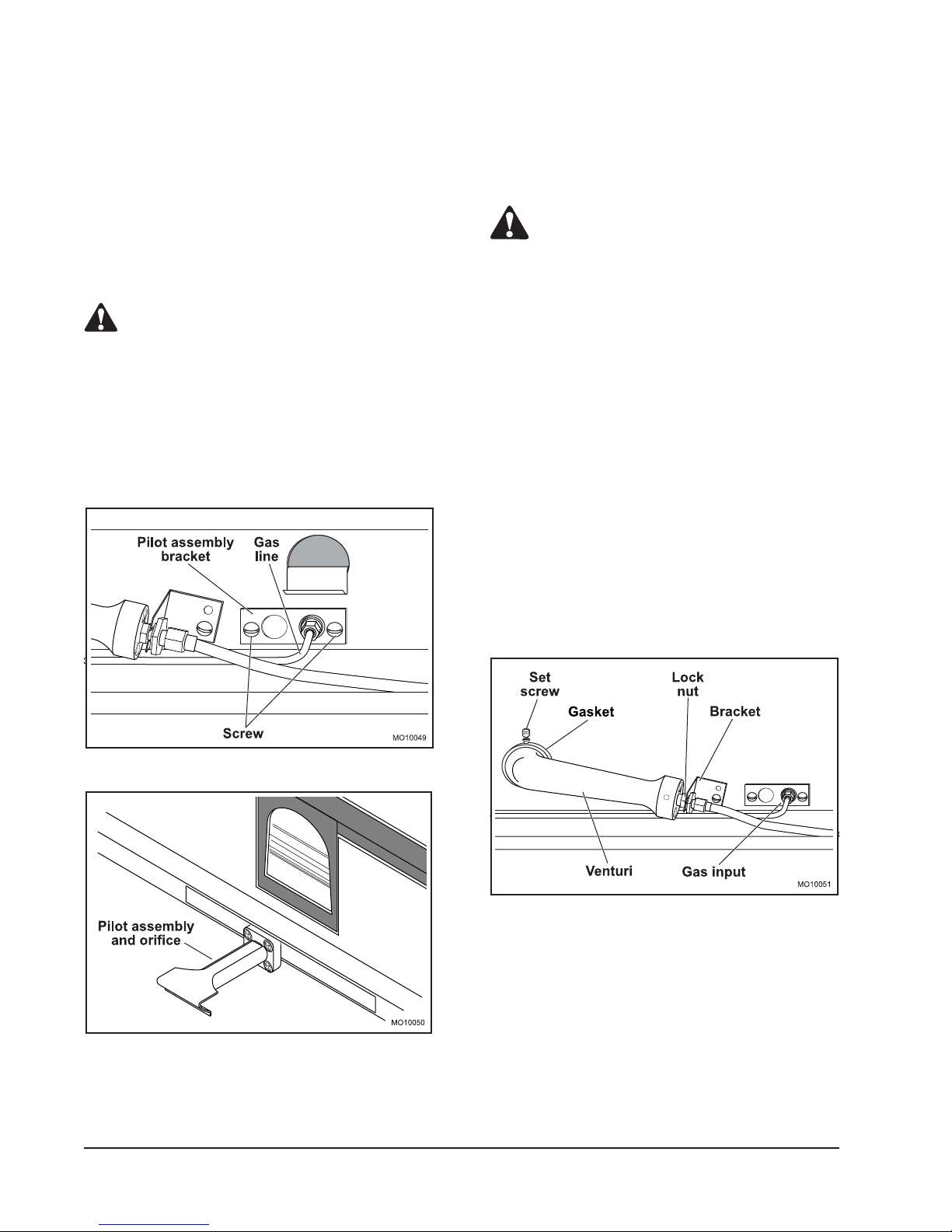
4. Install the new pilot assembly, orifice and pilot
assembly bracket.
5. Connect the gas line to the back of pilot assembly.
NOTE: Make sure that the pipe joint compound or
pipe thread sealant that is being used is resistant
to the corrosive actions of liquefied petroleum gases.
MAIN BURNERS
The connection for the burners is accessed by removing
the venturi cover. The burners are accessed by
removing the grids and carriage. The burner valves are
accessed by removing the control panel cover.
CAUTION
6. Turn the main gas shutoff valve to the broiler to
the ON position.
WARNING
ALL GAS JOINTS DISTURBED DURING
SERVICING MUST BE CHECKED FOR LEAKS.
CHECK WITH A SOAP AND WATER SOLUTION
(BUBBLES). DO NOT USE AN OPEN FLAME.
7. Light pilot and adjust pilot valve.
8. Reinstall venturi cover, heat shield, insulation and
exterior top.
Turn off the gas supply at the main shutoff
valve that is next to the broiler before
attempting to loosen any gas connections.
Burner Assembly, Orifice and Venturi
1. Remove the venturi cover as described in COVERS
AND PANELS.
2. Remove the ceramic radiants from each side of
the main burner to be replaced.
3. Loosen the set screw that attaches the main
burner to the venturi assembly.
4. Slide the main burner out of the broiler.
5. If the venturi or orifice is to be replaced, disconnect
the gas input to the venturi. Remove the gasket.
Replace the gasket every time the venturi or
burner is removed.
6. Loosen the lock nut so that the venturi can be
removed from the bracket.
Figure 6. Pilot Assembly Connection
Figure 7. Pilot Assembly
SM-8
Figure 8. Burner Pilot Assembly
7. Remove the orifice hex nut fitting from the venturi.
8. Remove the orifice from the hex nut fitting.
NOTE: Make sure that the pipe joint compound or
pipe thread sealant that is being used is resistant
to the corrosive actions of liquefied petroleum gases.
The MONTAGUE Company
 Loading...