

Montague 2-115A Installation Manual
INSTRUCTION MANUAL
MONTAGUE
Gas Convention
Ovens
MODELS:
70, 115, R85, 2-70, 2-115, & R2-85 Series
These instructions should be read thoroughly before attempting installation.
Set up and installation should be performed by qualified installation personnel.
Keep area around appliances free and clear from combustibles.
PLEASE RETAIN THIS MANUAL
FOR FUTURE REFERENCE.
THE MONTAGUE COMPANY
1830 Stearman Avenue
P.O. BOX 4954
Hayward, CA 94540-4954
TEL: (510) 785-8822 FAX: (510) 785-3342

IMPORTANT
TABLE OF CONTENTS
Important (Cautions and Warnings) ........................................................... Page 1
Installation .................................................................................................... Page 2 - 10
Operation ...................................................................................................... Page 11 - 12
Cooking Hints .............................................................................................. Page 13 - 17
Maintenance ................................................................................................. Page 18 - 20
Maintenance Schedule ................................................................................ Page 21
Service .......................................................................................................... Page 22 - 33
Orifice Size Chart - Drill Size ....................................................................... Page 34
Exploded View ............................................................................................. Page
Exploded View Parts List ............................................................................ Page
Wire Diagram ................................................................................................ Page
SHIPPING DAMAGE CLAIM PROCEDURE
For your protection, please note that equipment in this shipment was carefully inspected and packed
by skilled personnel before leaving the factory. The transportation company assumed full
responsibility for safe delivery upon acceptance of this shipment.
If shipment arrives damaged:
1. VISIBLE LOSS OR DAMAGE - Be certain this is noted on freight bill or express receipt, and
signed by person making delivery.
2. FILE CLAIM FOR DAMAGES IMMEDIATELY - Regardless of the extent of damage.
3. CONCEALED LOSS OR DAMAGE - If damage is unnoticed until merchandise is unpacked,
notify transportation company or carrier immediately, and file “concealed damage” claim with
them. This should be done within fifteen (15) days of date that delivery was made to you. Be sure
to retain container for inspection.
We cannot assume responsibility for damage incurred in transit. We will, however, be glad to furnish you with
IMPORTANT
FOR YOUR SAFETY
WARNING
IMPROPER INSTALLATION, ADJUSTMENT, ALTERATION, SERVICE OR MAINTENANCE CAN
CAUSE PROPERTY DAMAGE, INJURY OR DEATH. READ THE OPERATING AND
MAINTENANCE INSTRUCTIONS THOROUGHLY BEFORE INSTALLING OR SERVICING THIS
EQUIPMENT.
WARNING
DO NOT STORE OR USE GASOLINE OR OTHER FLAMMABLE VAPORS AND LIQUIDS IN THE
VICINITY OF THIS OR ANY OTHER APPLIANCE.
NOTE: This manual has been prepared for personnel qualified to install commercial
equipment who should perform the initial field start-up and the adjustments of the equipment
covered by this manual.
NOTE: Instructions to be followed in the event the user smells gas must be posted in a
prominent location. This information may be obtained by consulting the local gas supplier.
1

INSTALLATION
Vectaire gas convection ovens are
manufactured for use with the type of gas and
electric supply indicated on the nameplate
behind the fire box panel.
The Vectaire oven is produced with the best
possible material and workmanship.
Proper installation is essential for safe and
efficient trouble-free operation.
NOTE: The installation instructions
contained herein are for the use of qualified
installation and service personnel only.
Installation or service by other than qualified
personnel may result in damage to the oven
and/or injury to the operator.
Qualified installation personnel are individuals,
a firm, corporation or company which either in
person, or through a representative are
engaged in, and are responsible for:
1. The installation or replacement of gas
piping or the connection, installation, repair
with the national fuel code, ANSI Z223.1-latest
addenda, including:
1. The appliance and its individual shutoff
valve must be disconnected from the gas
supply piping system during any pressure
testing of that system at test pressures in
excess of 1/2 psig. (3.45kPa).
2. The appliance must be isolated from the
gas supply piping system by closing its
individual manual shutoff valve during any
pressure testing of the gas supply piping
system at test pressure equal to or less
than 1/2 psig. (3.45kPa).
This unit when installed must be electrically
grounded in accordance with local codes, or in
absence of local codes, with the national
electrical code, ANSI/NFPA No. 70–latest
addenda.
Provisions must be made for adequate air
supply to the unit.
or servicing of equipment, who is
experienced in such work, familiar with all
precautions required, and has complied
with all requirements of state or local
authorities having jurisdiction. Reference:
National Fuel Gas Code Z223.1-latest
addenda, Section 1.4.
DO NOT OBSTRUCT THE FLOW OF
COMBUSTION AND VENTILATION AIR TO
THE OVEN. KEEP THE APPLIANCE AREA
FREE AND CLEAR FROM COMBUSTIBLES.
CAUTION
2. The installation of electrical wiring from the
electric meter, main control box or service
outlet to the electric appliance. Qualified
personnel must be experienced in such
work, be familiar with all precautions
required and have complied with all
requirements of state and local authorities
having jurisdiction. Reference: National
Electric Code, N.F.P.A. No. 70– latest
addenda.
Read carefully and follow these
instructions.
The oven must be installed in accordance with
local codes, or in the absence of local codes,
Solid state components have a very short life
span when exposed to temperatures above
185°F (85°C), therefore, certain installation
precautions are necessary. The Vectaire SL
ovens have been designed to operate below
this temperature when properly installed. The
following precautions must be observed:
1. Do not obstruct the flow of air through the
vent openings at the top of the oven, or the
flow of room air to the oven bottom or
lower front portion of the burner access
panel.
2
INSTALLATION
2. Do not mount the oven on a curb unless it
has been equipped with the No. 555 Toe
Base (P/N: 06024-0) for this type of
installation.
3. When stacking ovens, never reverse the
top and bottom oven sections.
4. Never stack an “SL” series convection
oven with a standard Vectaire or another
brand of oven without first consulting the
factory. Certain ovens are not compatible,
or a stacking kit may be required.
SPECIAL CAUTION
DO NOT PLACE HIGH HEAT PRODUCING
EQUIPMENT ADJACENT TO THE RIGHT
SIDE OF A SOLID STATE CONTROLLED
OVEN. SURFACE TEMPERATURES
EXCEEDING 185°F (85°C) CAN CAUSE
PREMATURE COMPONENT FAILURE NOT
COVERED UNDER MANUFACTURER’S
WARRANTY.
CAUTION
PROVISIONS MUST BE MADE TO ASSURE
ADEQUATE AIR SUPPLY TO UNIT FOR
PROPER BURNER OPERATION.
CLEARANCES
Adequate clearances must be provided in the
aisle and at the side and back to allow the
doors to open sufficiently to permit the
removal of the racks and for serviceability.
Adequate clearance for air openings into the
combustion chamber must be provided.
Care must be taken to prevent the motor from
overheating. A minimum of one inch (2.54 cm)
clearance must be maintained behind the
motor to provide air circulation.
The following is the minimum clearance from
combustible material and non-combustible
material.
6” LEGS: SUITABLE FOR INSTALLATION
Location Combustible
Construction
Back Wall
Left Side
Right Side
6” 5”
6” 0”
6” 0”
Noncombustible
Construction
On combustible floors. Curb mount with 1” toe
base (P/N: 6024-0): for use only with noncombustible floors.
VENTILATING HOOD
The unit must be installed under a properly
designed ventilating hood. The hood should
extend at least 6” beyond all sides of the unit.
The hood should be connected to an
adequate mechanical exhaust system.
Information on the construction and
installation of ventilating hoods may be
obtained from the “Standard for the Installation
of Equipment for the Removal of Smoke and
Grease Laden Vapors from Commercial
Cooking Equipment,” NFPA No. 96 - latest
addenda, available from the National Fire
Protection Association, Batterymarch Park,
Quincy, Ma 02269.
It is also necessary that sufficient room air
ingress be allowed to compensate for the
amount of air removed by the ventilating
system. Otherwise, a subnormal atmospheric
pressure will occur which may interfere with
burner performance or may extinguish the
flame. In case of unsatisfactory oven
performance, check with the exhaust fan in
the “OFF” position.
DIRECT FLUE CONNECTION
If the oven is connected directly to an outside
flue, a draft hood P/N: 04392-3 for
3
INSTALLATION
Model 70, 115, SL70 and SL115 series and P/
N: 03099-6 for Model 2-70, 2-115, SL2-70 and
SL2-115 series must be used. The flue should
rise at least 10 feet above the roof or any
surrounding structure. The flue should rise at
least 10 feet above the roof or any
surrounding structure. The flue must be
terminated with an U.L. listed vent cap or
spinner.
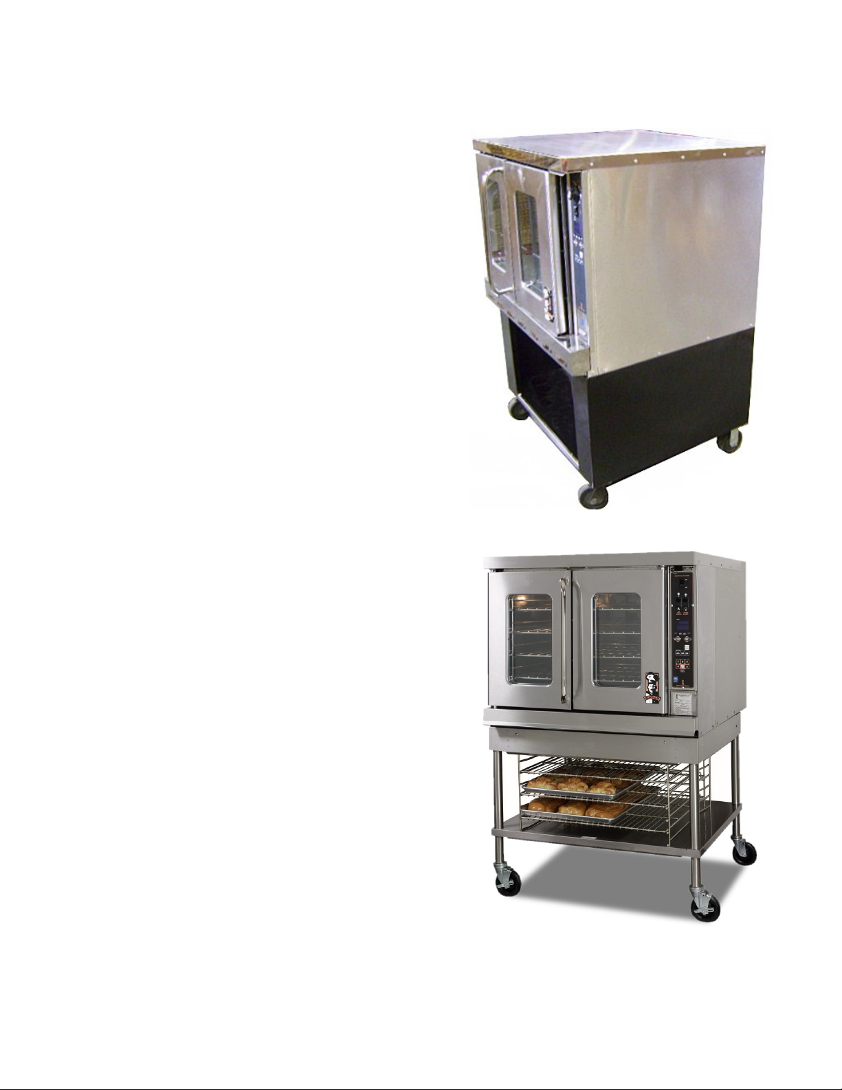
ASSEMBLY
Vectaire Models: 70, 115, SL70 & SL115
Series (See Figure 1 & 2)
Attaching Gusset Legs
Uncrate oven and base as near to final
location as possible.
Remove all packing material and
accessories from oven interior.
Install rack guides (if provided) in base.
Place oven on stand as shown in Figure 1.
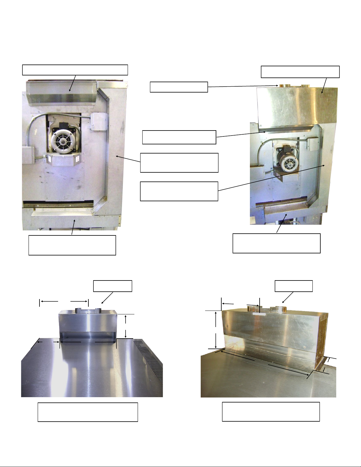
Install flue deflector (P/N: 16522-0 or
16532-8) or draft hood (P/N: 04391-5 or
04392-3). Either a flue deflector or a draft
hood is shipped with every unit. The flue
deflector is intended for use when the oven
is installed under a properly designed
hood.
When oven is directly connected to vent
system, the draft hood must be used
(See Figure 2 & 5). When oven is in
permanent position, level entire unit by
placing carpenter’s level on oven rack and
adjusting the foot of the bottom of each leg
so that oven is level from front to back and
side to side.
Enclosed Based
Modular Stand
(Figure 1)
4

INSTALLATION
Tighten the knurled lock nut by hand until
the caster is secure inside tube of leg.
Secure the Caster Restraint Mount to the
bottom of the oven directly below the gas
inlet pipe. Use the hex head screws
supplied.
Insert the non-locking casters into the rear
legs.
Tighten the knurled lock nut by hand until
the caster is secure inside the legs.
Flue Deflector
P/N: 16532-8 (S/S)
Lower unit in place and lock the front
casters.
The caster restraint cable should be
attached to the exposed hole in the Caster
Restraint Mount.
NOTE: For an appliance equipped with
casters the installation shall be made with a
connector that complies with the Standard for
Connectors for Movable Gas Appliances,
ANSI Z21.69 or Connectors for Movable Gas
Appliances, CAN/CGA-6.16, and a quick-
Draft Hood
P/N: 4392-3 (S/S)
(Figure 2)
disconnect device that complies with the
Standard for Quick-Disconnect Devices for
Use With Gas Fuel, ANSI Z21.41, or Quick
Disconnect Devices for Use with Gas Fuel,
Can 1-6.9.
CASTER AND CASTER RESTRAINT
INSTALLATION
The casters are available as an option to
the bullet-style feet (gusset legs) and also
in plate style for double stacked units.
A lift with the proper weight capacity will be
needed to suspend the unit in order to
install the casters.
Remove the bullet style feet from the legs.
Insert the locking casters into the bottom of
the front legs.
Install rack guides inside oven. Place oven on
stand. Install flue deflector (P/N: 16539-5) or
drafthood (P/N: 3099-6). Either a flue deflector
or a drafthood is shipped with every unit. The
flue deflector is intended for use when the
oven is installed under a properly designed
hood. When the oven is directly connected to
the vent system, the draft hood must be used.
5
INSTALLATION
When the oven is in permanent position, level
entire unit by placing a carpenter’s level on the
oven rack and adjusting the foot on the bottom
of each leg so that the oven is level from front
to back and side to side.
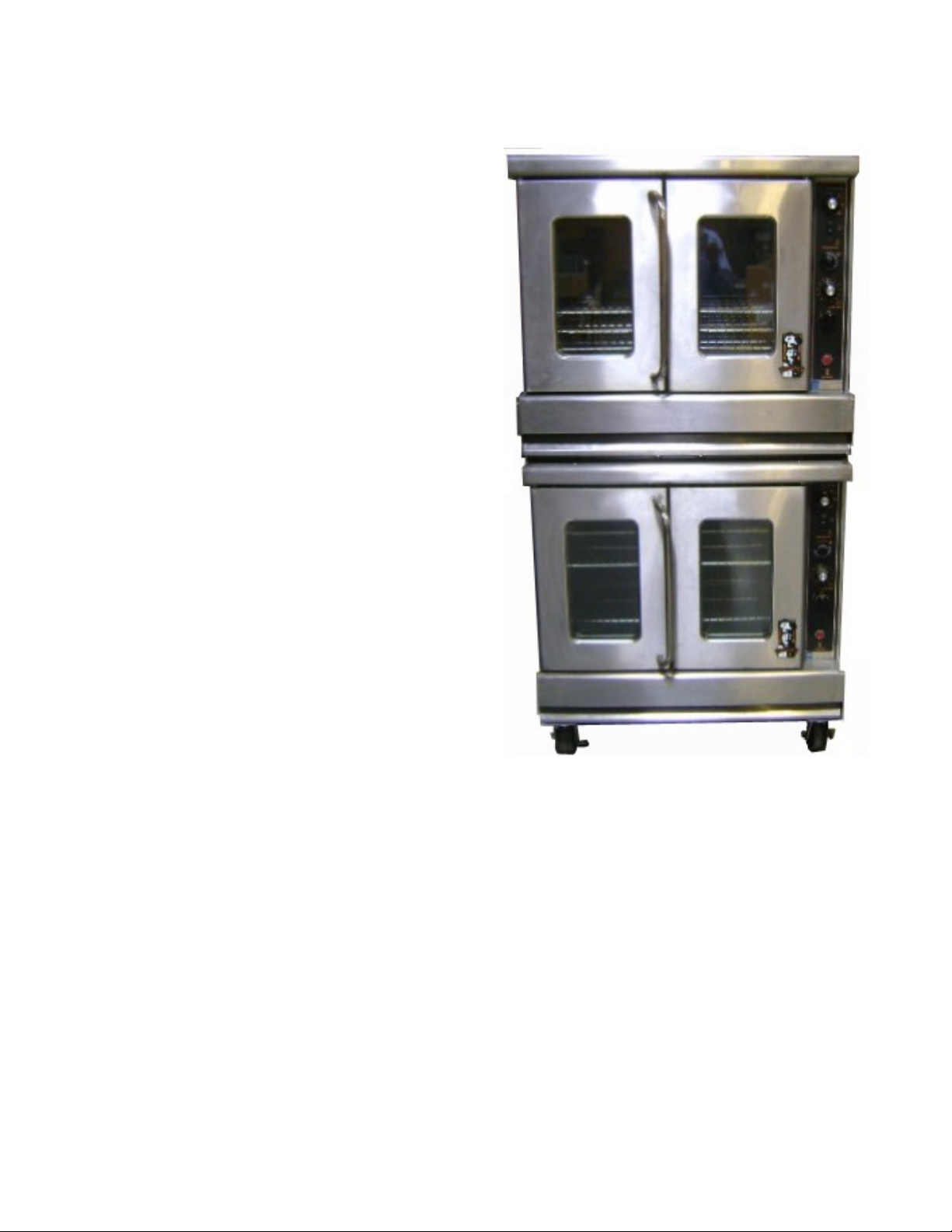
Vectaire Models: 2-70, 2-115, SL2-70 & SL2115 Series (See Figure 3-5)
1. Screw the adjustable feet of the legs in all
the way. Then tightly screw the complete
leg assembly into the mounting holes at
each corner of the lower deck (note: lugs
on top of lower deck). If unit is intended for
curb mounting, Toe Base (P/N: 6024-0)
must be used. The Toe Base is factory
installed when curb mount is specified.
2. Using a lift with the proper weight capacity,
set upper deck unit in place on top of lower
deck. There are lugs on the top panel of
the lower unit to assist in aligning upper
unit.
3. Install flue riser (P/N: 4437-7) over outlet of
horizontal flue collector (P/N: 4439-3) of
the lower deck. Secure in place with the
screws that are provided. Install flue
deflector (P/N: 16539-5) over flue outlet of
top oven section.
4. Install low profile deflector trim (P/N: 26604
-3) or draft hood (P/N: 24678-6). Either a
flue deflector or a draft hood is shipped
with every unit. The flue deflector is
intended for use when the oven is installed
under a properly designed hood. When the
oven is directly connected to the vent
system, the draft hood must be used.
(Figure 3)
6
INSTALLATION
Flue Deflector SS P/N: 16539-5
Flue Collector Alzd P/N: 4439-3
SS 4443-1
Drafthood SS P/N: 3099-6
FOR 8” VENT PIPE
Flue Box SS P/N: 16532-8
Flue Riser Alzd P/N: 4437-7
SS 4445-8
Flue Riser Alzd P/N: 4437-7
SS 4445-8
Flue Collector Alzd P/N: 4439-3
SS 4443-1
6” Oval Vent
16”
7 1/2”
19”
P/N: 4392-3 SS FOR MODELS
70, 115, SL70, AND SL115
10”
(Figure 4)
(Figure 5)
8” Oval Vent
13 1/2”
11”
27”
P/N: 3099-6 SS FOR MODELS
2-70, 2-115, SL2-70 AND SL2-115
8 1/2”
7
INSTALLATION
5. When oven is in permanent position, level
entire unit by placing a carpenter’s level on
the oven rack and adjusting the foot on the
bottom of each leg, so that the oven is
level from front to back and side to side.
Level a curb mounted unit by placing
shims under the low side.
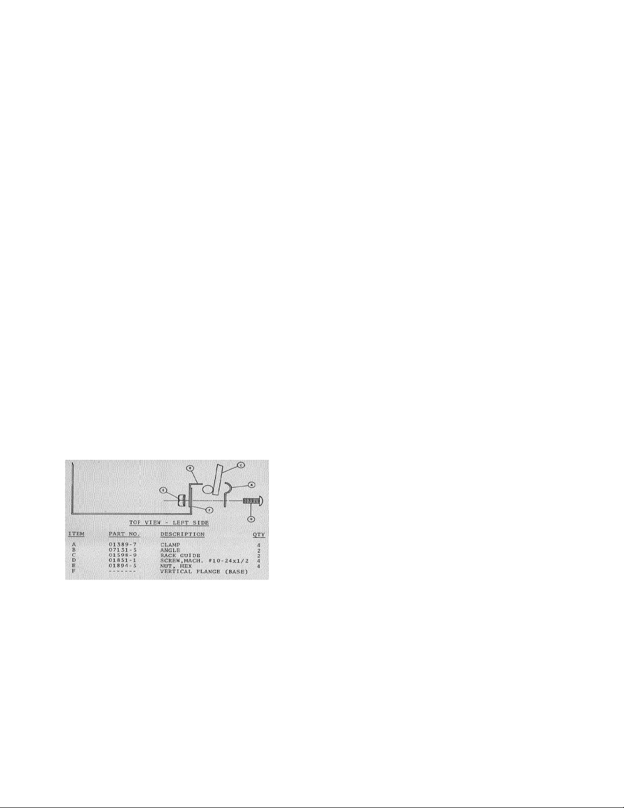
INSTALLATION OF RACK GUIDES IN BASE
(KIT NO. 04651-5) (If Provided See Figure 6)
1. Set base upright and place on rack guide
in position with rod extensions toward rear
and through holes in back.
2. Install stop (B) behind vertical flange
forming base opening.
3. Place screw through clamp (A), upper hole
of base flange (B) and stop. Install nut.
4. Repeat step 3 with lower hole of flange
and stop. Tighten both nuts.
5. Repeat step 2, 3, and 4 for installation of
other rack guide on opposite side.
holes with the holes on the bottom of the
oven. Secure the leg using the provided 3/8”
bolts and washers. Repeat the procedure for
the rear corner of the side off the ground. Tip
the oven up on the secured legs and lean the
oven against a wall so that the legs on the
remaining side can be attached. Install the
remaining two legs using the aforesaid
procedure. Tip the oven back down on the
newly installed legs and re-tighten all the bolts
securely.
A flue detector is supplied with the gusset
legs. A Draft Hood is also available and
replaces the flue deflector. Either a flue
deflector or a draft hood must be installed on
the unit. The flue detector is intended for use
when the oven in installed under a properly
designed hood. When the oven is directly
connected to a vent system, the draft hood
must be used.
When the oven is in permanent position, level
entire unit by placing a carpenter’s level on the
oven rack and adjusting the foot on the bottom
of each leg so that the oven is level from front
to back and side to side.
(Figure 6)
MODEL R85
Uncrate oven and base as near to final
location as possible. Remove all packing
material and accessories from oven interior.
Using a lift with the proper weight capacity
suspend unit. Insert the leg into the nut and
turn the leg clockwise. Tighten the leg to the
oven securely. Rotate the leg counterclockwise slightly to align the two leg plate
MODEL R2-85 SERIES
Using a lift with the proper weight capacity
suspend unit. Screw the adjustable feet of the
legs in all the way. Then tightly screw the
complete leg assembly into the mounting
holes at each corner of the lower R85 unit.
Mount lugs on top of the lower R85 unit, as to
center the top unit on the lower one.
Using a lift with the proper weight capacity.
Set upper deck unit in place on top of lower
deck.
Locate the flue riser, the flue collector, and the
flue deflector. Install the flue collector over the
flue outlet on the lower R85 unit. Install the
flue riser over the outlet of the
8

INSTALLATION
horizontal flue collector. Secure in place with
self-drilling sheet-metal screws. Install the flue
deflector over the flue outlet of the upper R85
unit. This setup is intended for use when the
oven is installed under a properly designed
hood.
Note: When the oven is to be directly
connected to a vent system, a draft hood must
be used in conjunction. Replace the flue
deflector with the Draft Hood ensuring that it
covers the flue outlet of the upper R85 unit. It
must cover the top of the flue riser as well.
When the oven is in permanent position, level
entire unit by placing a carpenter’s level on the
oven rack and adjusting the foot on the bottom
of each leg, so that the oven is level from front
to back and side to side.
GAS CONNECTION
Before connecting oven to the gas supply line,
be sure that all new piping has been cleaned
and purged to prevent any foreign matter from
being carried into the controls by the gas. In
some cases, filters or drops are
recommended. A separate gas shutoff valve
must be installed upstream from the gas
pressure regulator adjacent to the oven and
be located in an accessible area.
It is important that adequately sized piping be
run directly to the point of connection at the
oven, with as few elbows and tees as
possible. Consult local gas company for
proper piping size and gas pressure.
Each oven is equipped with an appliance gas
pressure regulator. This gas pressure
regulator is factory adjusted for the manifold
pressure specified on the name plate.
Note: If using pressure test do not exceed
manufacturer specification of 1/2 psi or
damage to the regulator may occur.
For Natural Gas
This gas pressure regulator is factory adjusted
for 3.5” Water Column (W.C.) manifold
pressure. The maximum inlet pressure to the
regulator should not exceed manufacturers
specification of 1/2 psi.
For Propane Gas
This pressure regulator is factory adjusted for
10.0” W.C. manifold pressure. The maximum
inlet pressure to the regulator should not
exceed manufacturers specification of 1/2 psi.
Connect the gas supply line from the service
gas shutoff valve to the inlet on the unit using
3/4” pipe and 3/4” reducer. If flexible or
semi-flexible connectors are used, an AGA
listed flexible connector with an I.D. equal to
3/4” pipe must be used. Do not use a
domestic appliance type gas flexible
connector. Avoid kinks or sharp bends that
could restrict gas flow.
Pipe joint compound or thread sealant that
is used should be resistant to action of
liquefied petroleum gases.
Turn gas shutoff valve “ON” and immediately
check carefully for gas leaks. Do this before
attempting to operate the oven.
Test all pipe joints for leaks before operating
oven. This includes all gas connections that
may have loosened during shipment. Use a
rich soap solution (or other accepted leak
tester) around all pipe connections and all
other joints. Do not use an open flame.
Absolutely no leakage should occur, otherwise
there is a danger of fire or explosion
depending upon conditions. Never use if
leakage is detected.
ELECTRICAL CONNECTION
Unless otherwise specified, the oven is
equipped with a 6 foot flexible supply cord for
115 VAC, 60 hertz. A terminal block is
provided for 208/240 VAC, 60 hertz, single or
9

INSTALLATION
three phase units. The wiring diagram is
located on the back of the oven.
WARNING
THIS APPLIANCE, WHEN INSTALLED,
MUST BE ELECTRICALLY GROUNDED IN
ACCORDANCE WITH LOCAL CODES, OR
IN THE ABSENCE OF LOCAL CODES,
WITH THE NATIONAL ELECTRICAL CODE,
ANSI/NFPA No. 70-LATEST ADDENDA.
115 VAC - 60 Hz - Single Phase
Ovens with this electrical rating are factory
supplied with a three-wire cord and threeprong plug which fits any standard three-prong
grounded receptacle. A separate 15 ampere
supply is needed for each oven.
ELECTRICAL GROUNDING INSTRUCTIONS
This appliance is equipped with a three-prong
(grounding) plug for your protection against
shock hazard and should be plugged directly
into a properly grounded three-prong
receptacle. Do not cut or remove the
grounding prong from this plug.
115/208-240 VAC - 60Hz - Single Phase (3
Wire)
Ovens with this electrical rating are factory
equipped with a 3 pole terminal block. To
connect supply wires, remove cover from
junction box at right rear of oven. Route
supply wires and ground wire through hole
with strain relief fitting at bottom of connection
box. Attach supply wires to proper terminals of
terminal block. Attach ground wire to ground
lug inside connection box. See wiring diagram
for proper connection.
10

OPERATION
GAS CONTROL SYSTEM (ALL MODELS
EXCEPT WITH SUFFIX “EI”)
Lighting
Turn on main gas shutoff valve and electrical
service.
In the event a gas odor is detected, shut
down units at main shutoff valve and
contact the local gas company or gas
supplier for service.
1. Turn oven burner valve clockwise to “OFF”
position.
2. Remove burner compartment access panel
below oven doors by pulling insert access
panel outward to disengage panel catches.
3. Press and hold red safety pilot in and apply
lit extended lighter or match to pilot burner.
After pilot burner ignites, continue to hold
red button depressed for 30-45 seconds or
until pilot remains burning when button is
released.
4. Replace burner compartment access
panel.
5. Set thermostat to desired temperature.
6. Turn oven burner valve counterclockwise
to “ON” position.
b. Turn fan off.
c. Turn electrical service off
disconnect electrical supply cord
from wall receptacle.
Relighting (Standard Pilot)
1. Turn oven burner valve to “OFF” position.
2. Wait five (5) minutes then follow “Lighting”
instructions.
GAS CONTROL SYSTEM (MODELS WITH
SUFFIX “EI”) (EQUIPPED WITH
ELECTRONIC IGNITION SYSTEM)
Operation
1. Turn rotary switch to cool, hi, or lo position.
2. Set thermostat to desired temperature.
3. Push toggle of Start/Reset switch to “UP”
position and release. The electronic pilot
ignition control will automatically light the
pilot and burner each time the thermostat
calls for heat.
4. If pilot fails to ignite within 30 seconds, a
complete shut down of the ignition system
will occur. To initiate a re-ignition, wait at
least 30 seconds, push toggle of Start/
Reset switch up, then release.
7. Turn on fan. Fan should be on at all times
during cooking operation.
Shut Down
1. Stand By
a. Turn oven burner valve to “OFF”
position.
b. Turn off fan.
2. Complete
a. Turn all gas valves to “OFF”
position.
NOTE: Instructions for pilot re-lighter: hold
safety valve red button in while re-ignition
switch is in re-light position.
CAUTION
DO NOT ATTEMPT TO LIGHT THE PILOT
MANUALLY WITH A MATCH. THIS COULD
RESULT IN THE MAIN VALVE BEING
ENERGIZED IMMEDIATELY.
Shut Down
1. Turn manual valve to “OFF” position.
11

OPERATION
2. Turn thermostat to lowest setting.
CONTROLS (STANDARD MODELS)
(MODELS WITH SUFFIX “AE, AG, ZE, ZG”)
1. “LIGHT-OFF” switch controls the oven
interior lights.
2. Four position rotary switch controls the fan
operation. It must be on to obtain
satisfactory performance.
a. The first position is “OFF.” The
second position is cool down. The
third position is “HI.” The fourth
position will either be “OFF” or
“LO,” depending on the option for
2 speeds.
b. “HI” or “LOW” position causes the
motor to run continuously when
doors are closed. When doors are
opened, fan will stop. These
positions are for cooking.
c. Cool down will result in continuous
blower operation even with doors
open. This position is intended for
cooling the oven at the end of
work period or lowering oven
temperature.
NOTE: When cooling oven down, the
burner valve should be turned off to prevent
burner operation.
3. The thermostat controls the oven
temperature. The “BURNER” indicator light
remains lit until desired oven temperature
is reached.
4. The timer is only a time reminder. It has no
control over the oven. Turn dial past to
minimal mark.
12
 Loading...