

Montague 136W36 Installation Manual
INST ALLA TION &
OPERA TION MANUAL
G
AS FIRE
D
BR
O
E36W36 EV136W36 EC36
E43W36 E236W36 EC45
E136W36 E243W36
ILERS
G
I
S
N
E
D
THE M
ONTAGUE CO.
C
E
D
R
E
I
T
F
I
Please read this manual completely before attempting to
install or operate this equipment! Notify carrier of damage.
Inspect all components immediately . See page 4.
RETAIN THIS MANUAL FOR FUTURE REFERENCE.
The MONTAGUE Company
1830 Stearman A ve. • P.O. Box 4954 • Hayward, CA 94540-4954 • Tel: 510/785-8822 • Fax: 510/785-3342
IMPORTANT FOR YOUR SAFETY
THE INSTALLATION INSTRUCTIONS CONTAINED HEREIN ARE FOR THE USE OF QUALIFIED
INSTALLATION AND SERVICE PERSONNEL ONLY. INSTALLATION OR SERVICE BY OTHER THAN
QUALIFIED PERSONNEL MAY RESULT IN DAMAGE TO THE UNIT AND/OR INJURY TO THE OPERATOR.
IF YOU SMELL GAS
1. TURN OFF THE APPLIANCE AT THE GAS INLET COCK AND OPEN ALL DOORS
AND WINDOWS.
2. DO NOT OPERATE ANY ELECTRICAL SWITCHES AND EXTINGUISH ALL
NAKED FLAMES.
3. CONTACT THE LOCAL GAS AUTHORITY IMMEDIATELY.
THE FOLLOWING INSTRUCTIONS SHOULD BE READ CAREFULLY AS THE
MANUFACTURER CANNOT BE HELD RESPONSIBLE FOR ANY DAMAGE
TO PROPERTY, PERSONS OR ANIMALS CAUSED BY INCORRECT
INSTALLATION OR OPERATION OF THE APPLIANCE.
POST IN A PROMINENT LOCATION THE INSTRUCTIONS TO BE FOLLOWED
IN THE EVENT THE SMELL OF GAS IS DETECTED. THIS INFORMATION CAN
BE OBTAINED FROM THE LOCAL GAS SUPPLIER.
IN THE EVENT OF A POWER FAILURE, DO NOT ATTEMPT TO OPERATE THIS DEVICE.
IMPORTANT
IN THE EVENT A GAS ODOR IS DETECTED, SHUT DOWN UNITS AT MAIN
SHUTOFF VALVE AND CONTACT THE LOCAL GAS COMPANY OR GAS
SUPPLIER FOR SERVICE.
FOR YOUR SAFETY
DO NOT STORE OR USE GASOLINE OR OTHER FLAMMABLE VAPORS
OR LIQUIDS IN THE VICINITY OF THIS OR ANY OTHER APPLIANCE.
Improper installation, adjustment, alteration, service or
maintenance can cause property damage, injury or death. Read the
INSTALLATION, OPERATING AND MAINTENANCE INSTRUCTIONS
thoroughly before installing, servicing or operating this equipment.
I&O-2
SAVE THESE INSTRUCTIONS FOR FUTURE USE.
The MONTAGUE Company

TABLE OF CONTENTS
IMPORTANT FOR YOUR SAFETY ..................................................................................................................2
INTRODUCTION ................................................................................................................................................ 4
GENERAL...................................................................................................................................................4
MODELS ....................................................................................................................................................4
DATA PLATE LOCATION...........................................................................................................................4
SERIAL NUMBER LOCATION ...................................................................................................................4
RECEIVING AND INSPECTING THE EQUIPMENT................................................................................... 4
SPECIFICATIONS ...................................................................................................................................... 5
INSTALLATION .................................................................................................................................................6
STATUTORY REGULATIONS ..........................................................................................................................6
CLEARANCES ...........................................................................................................................................6
VENTILATING HOOD .................................................................................................................................6
VENTILATION AIR......................................................................................................................................6
ASSEMBLY................................................................................................................................................6
Legs......................................................................................................................................................6
Ceramic Radiants ................................................................................................................................7
LOCATION ..................................................................................................................................................7
SITING ........................................................................................................................................................7
BATTERY ARRANGEMENT ......................................................................................................................7
Setting In Place ................................................................................................................................... 7
Floor Mounted Ranges.........................................................................................................................8
GAS SUPPLY ............................................................................................................................................8
GAS CONNECTION....................................................................................................................................8
GAS PRESSURE REGULATOR................................................................................................................9
Adjustment Procedure ....................................................................................................................... 10
PILOT INITIAL ADJUSTMENT ..................................................................................................................11
BURNER ADJUSTMENT .......................................................................................................................... 11
OPERATION ................................................................................................................................................... 12
GENERAL................................................................................................................................................. 12
OPERATING CONTROLS ........................................................................................................................ 12
Gas Control ........................................................................................................................................ 12
Lighting/Relighting Pilot and Main Burner ..................................................................................12
Shutdown .....................................................................................................................................13
Grid Height Adjustment ..................................................................................................................... 13
GENERAL MAINTENANCE............................................................................................................................14
GENERAL CLEANING ............................................................................................................................. 14
Daily ................................................................................................................................................... 14
PAINTED SURFACES.............................................................................................................................. 14
Exterior............................................................................................................................................... 14
Interior ................................................................................................................................................14
STAINLESS STEEL SURFACES............................................................................................................. 14
VENTILATION ........................................................................................................................................... 15
SAFETY .................................................................................................................................................... 15
SERVICING .............................................................................................................................................. 15
C36 & C45 EXPLODED VIEW........................................................................................................................ 16
C36 & C45 PARTS LIST ................................................................................................................................. 17
36W36 & 43W36 EXPLODED VIEW.............................................................................................................. 18
36W36 & 43W36 PARTS LIST ....................................................................................................................... 19
GAS FIRED BROILERS
I&O-3
INTRODUCTION
GENERAL
The gas broilers covered in this manual are
manufactured for use with the type of gas
indicated on the nameplate. Some models
include a cabinet, conventional oven or
convection oven. Ovens are covered in separate
manuals. This manual only covers the broiler.
Montague gas broilers are produced with the
best possible material and workmanship.
Proper installation is essential for safe,
efficient, trouble-free operation.
MODELS
MODEL CONSISTS OF
E36W36 Cabinet Base Broiler with
Warming Oven
E43W36 Cabinet Base Broiler with
Warming Oven
E136W36 Broiler with Conventional
Oven and Warming Oven
EV136W36 Broiler with Convection Oven
E236W36 Double Broiler
E243W36 Double Broiler
EC36 Broiler Only
EC45 Broiler Only
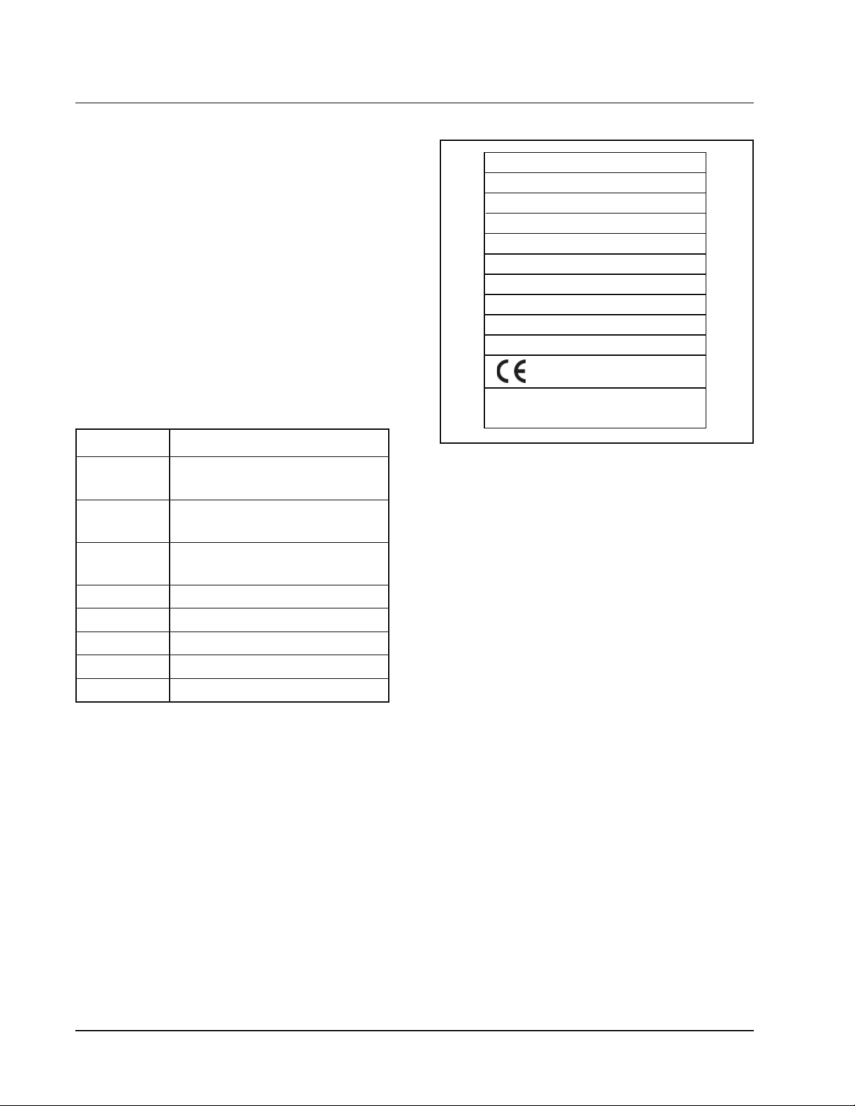
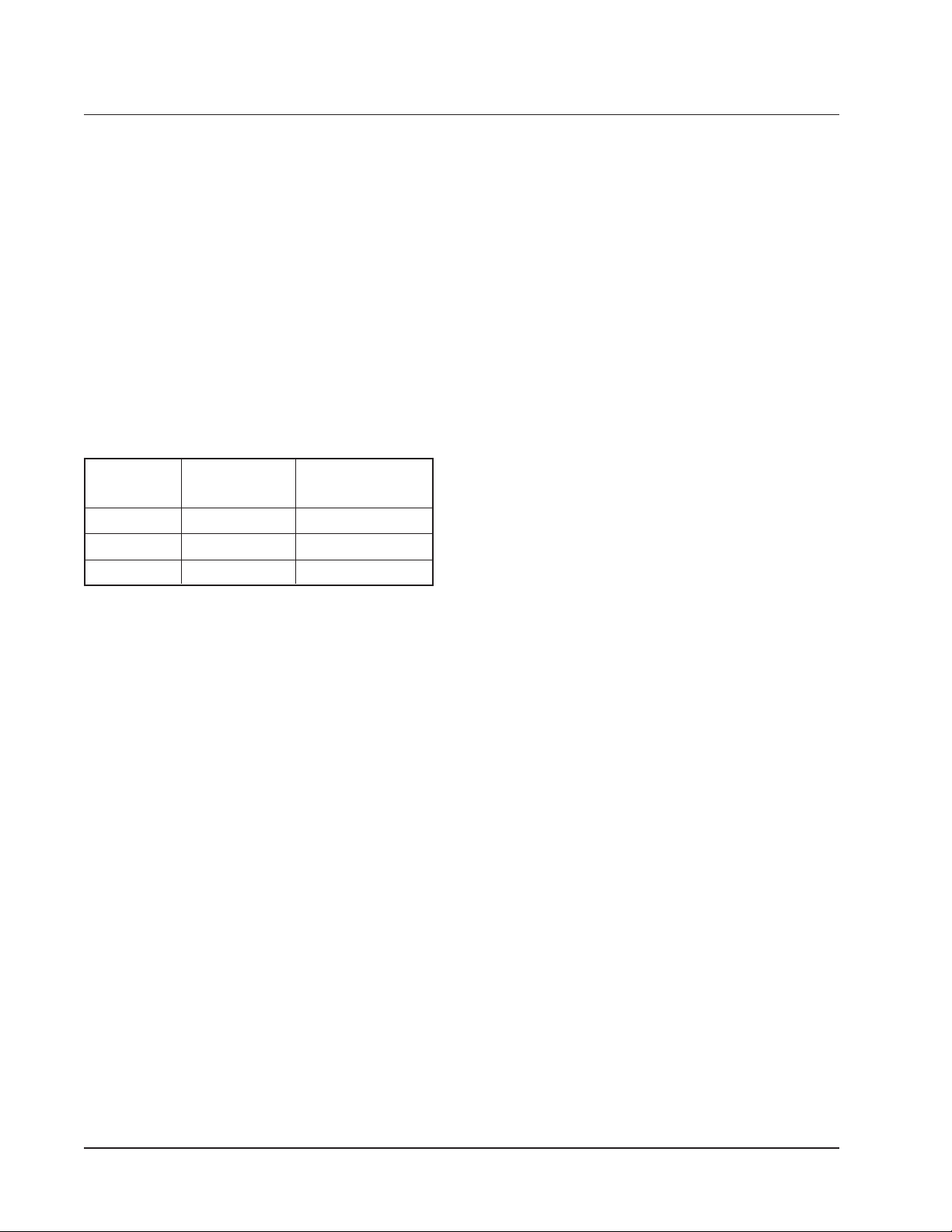
MODEL:
SERIAL NO.:
I TA
PN
EH
CATEGORY:
SUPPLY PRESSURE: mbar
GAS: SET PRESS: mbar
ELECTRICAL
VHzPh W
COUNTRY:
P.I.N.:
GAS CATERING EQUIPMENT
SALAMANDER - TYPE A
Wk:TU
THE MONTAGUE COMPANY
HAYWARD, CALIFORNIA USA
Figure 1. Typical Nameplate
RECEIVING AND INSPECTING
THE EQUIPMENT
Care should be taken during unloading so the
equipment is not damaged while being moved
into the building.
1. Visually inspect the exterior of the package
and skid or container. Any damage should
be noted and reported to the delivering
carrier immediately.
DATA PLATE LOCATION
The Data Plate is located on the front left of the
unit, at the level of the Control Valve panel.
SERIAL NUMBER LOCATION
Always have the serial number of your unit
available when calling for parts or service.
The serial number is on the nameplate that
also includes the model number. A typical
identification plate is shown in Figure 1.
I&O-4
2. If damaged, open and inspect the contents
with the carrier.
3. In the event that the exterior is not
damaged, yet upon opening, there is
concealed damage to the equipment, notify
the carrier. Notification should be made
verbally as well as in written form.
4. Request an inspection by the shipping
company of the damaged equipment. This
should be done within 10 days from receipt
of the equipment.
5. Freight carriers can supply the necessary
damage forms upon request.
6. Retain all shipping materials until an
inspection has been made or waived.
The MONTAGUE Company
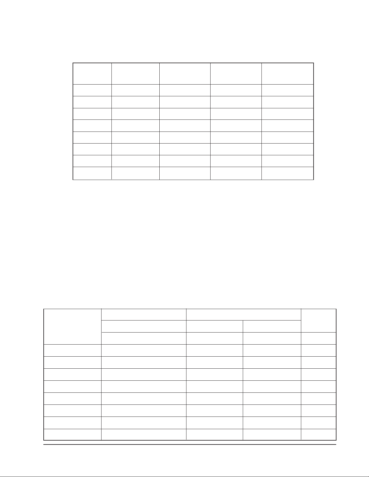
SPECIFICATIONS
Table A: Heat Input
MODEL
E36W36 2 123,000 ea. 123,000 ea. 24.6
E43W36 3 123,000 ea. 123,000 ea. 36.9
E136W36 2 123,000 ea. 123,000 ea. 36.3
EV136W36 2 123,000 ea. 123,000 ea. 36.3
E236W36 4 123,000 ea. 123,000 ea. 49.2
E243W36 6 123,000 ea. 123,000 ea. 73.8
EC36 2 123,000 ea. 123,000 ea. 24.6
EC45 3 123,000 ea. 123,000 ea. 36.9
NO. BURNERS G20 @ 20 mbar G31 @ 37 mbar TOT AL
(broiler only) kW kW kW
Table B: Setting Pressure/Injector Size
Manifold Pressure
G20: 15 mbar
G31: 25 mbar
G30: 25 mbar
Orifices
Fixed for specified gas type
G20: mm (#32 DMS)
G31: mm (#47 DMS)
Gas Inlet Size:
3/4" NPT at lower left rear (all
models)
NOTE: The pressure must be measured at the pressure test nipple located on
the manifold pipe with the burner lit.
Table C: Aeration Shutter/Pilot Flame Settings
MODEL 2nd FAMIL Y , GROUP H 3rd FAMIL Y , GROUP 3+
G20 @ 20 mbar G30 @ 30 mbar G31 @ 37 mbar
mm mm mm mm
E36W36 25 32 32 12.5
E43W36 25 32 32 12.5
E136W36 25 32 32 12.5
EV136W36 25 32 32 12.5
E236W36 25 32 32 12.5
E243W36 25 32 32 12.5
EC36 25 32 32 12.5
PILOT
FLAME
LENGTH
EC45 25 32 32 12.5
GAS FIRED BROILERS
I&O-5
INSTALLATION
CAUTION: Provision must be made to
assure adequate air supply to unit for
proper burner operation.
STATUTORY REGULATIONS
The installation of this appliance must be carried
out by a competent person and in accordance
with the relevant regulations, standards, codes
of practice and the related publications of the
country of destination.
CLEARANCES
The following are minimum clearances from
combustible and noncombustible materials.
Location Combustible Noncombustible
Construction Construction
Back Wall 152 mm 0 mm
Left Side 152 mm 0 mm
Right Side 152 mm 0 mm
With 152 mm legs: Suitable for installation on
combustible floors.
NOTE 1: The room containing the appliance
is required to have a permanent air vent. The
minimum effective area of the vent is related
to the maximum rated heat input of the
appliance and shall be 4.5 cm2 per kW in
excess of 7 kW.
NOTE 2: Air vents should be of such a size
to compensate for the effects of any extract
fan in the premises.
It is also necessary that sufficient room air
ingress be allowed to compensate for the amount
of air removed by the ventilating system.
Otherwise, a subnormal atmospheric pressure
will occur which may interfere with burner
performance or may extinguish the pilot flame.
In case of unsatisfactory broiler performance
check with the exhaust fan in the “OFF” position.
This appliance is to be installed with sufficient
ventilation to prevent the occurance of
unacceptable concentrations of substances
harmful to health in the room in which it is
installed.
Without legs: For use with special insulated
base on noncombustible floors only.
VENTILATING HOOD
The broiler(s) must be installed under a properly
designed ventilating hood. The hood should
extend at least 152 mm beyond all sides of the
unit. The hood should be connected to an
adequate mechanical exhaust system.
VENTALIATION AIR
The following notes are intended to give general
guidance. For detailed recommendations, refer
to the applicable code(s) in the country of
destination.
ASSEMBLY
Uncrate broiler as near to final location as
possible. For easier and lighter handling of broiler,
remove grids, grid frame, drip tray and grease
container. Remove all packing materials and
accessories from broiler interior.
Legs
Some broilers are mounted on legs.
1. Screws the legs into the modular stand.
2. Tightly screw the complete leg assembly
into the mounting holes in the bottom of the
broiler at each corner. If the unit is intended
for curb installation, no legs are provided.
The curb must be noncombustible material.
I&O-6
The MONTAGUE Company
 Loading...