

Page 1
INSTRUCTION MANUAL
MONTAGUE
Gas
Convection Ovens
MODELS:
70, 115, R85, 2-70,
2-115 & R2-85 Series
These instructions should be read thoroughly before attempting installation.
Set up and installation should be performed by qualified installation personnel.
Keep area around appliances free and clear from combustibles.
PLEASE RETAIN THIS MANUAL
FOR FUTURE REFERENCE.
THE MONTAGUE COMPANY
1830 Stearman Avenue P.O. BOX 4954
HAYWARD,CA 94540-4954
TEL: 510/785-8822 FAX: 510/785-3342
Page 2
CONTENTS
INSTALLATION ………. 3 MAINTENANCE ……… 21
OPERATION ………….. 11 SERVICE ……………… 26
COOKING HINTS ……. 16
IMPORTANT
WARNING:
Improper installation, adjustment,
alteration, service or maintenance
can cause property damage, injury
or death. Read the operating and
maintenance instructions thoroughly before installing or servicing this
FOR YOUR SAFETY:
Do not store or use gasoline or other
flammable vapors and liquids in the
vicinity of this or any other appliance.
equipment.
INSTRUCTIONS TO BE FOLLOWED IN THE EVENT THE USER SMELLS GAS MUST BE
POSTED IN A PROMINENT LOCATION. THIS INFORMATION MAY BE OBTAINED BY
CONSULTING THE LOCAL GAS SUPPLIER.
SHIPPING DAMAGE CLAIM PROCEDURE
For your protection, please note that equipment in this shipment was carefully inspected and packed
by skilled personnel before leaving the factory. The transportation company assumes full responsibility for safe delivery upon acceptance of this shipment.
If shipment arrives damaged:
1. VISIBLE LOSS OR DAMAGE—Be certain this is noted on freight bill or express receipt, and
signed by person making delivery.
2. FILE CLAIM FOR DAMAGES IMMEDIATELY—Regardless of the extent of damage.
3. CONCEALED LOSS OR DAMAGE—If damage is unnoticed until merchandise is unpacked,
notify transportation company or carrier immediately, and file “concealed damage” claim with
them. This should be done within fifteen (15) days of date that delivery was made to you. Be
sure to retain container for inspection.
We cannot assume responsibility for damage incurred in transit. We will, however, be glad to furnish
you with necessary documents to support your claim.
2
Page 3
INSTALLATION
Vectaire gas convection ovens are manufactured for use with the type of gas and electric supply indicated
on the nameplate behind the fire box panel.
The Vectaire oven is produced with the best possible material and workmanship. PROPER INSTALLATION
IS ESSENTIAL FOR SAFE AND EFFICIENT TROUBLE-FREE OPERATION.
THE INSTALLATION INSTRUCTIONS CONTAINED HEREIN ARE FOR THE
USE OF QUALIFIED INSTALLATION AND SERVICE PERSONNEL ONLY.
INSTALLATION OR SERVICE BY OTHER THAN QUALIFIED PERSONNEL
MAY RESULT IN DAMAGE TO THE OVEN AND/OR INJURY TO THE
OPERATOR.
Qualified installation personnel are individuals, a firm, corporation or company which either in
person, or through a representative are engaged in, and are responsible for:
A. The installation or replacement of gas piping or the connection, installation, repair or ser-
vicing of equipment, who is experienced in such work, familiar with all precautions required, and has complied with all requirements of state or local authorities having jurisdiction. Reference: National Fuel Gas Code Z223.1-latest addenda, Section 1.4.
B. The installation of electrical wiring from the electric meter, main control box or service out-
let to the electric appliance. Qualified personnel must be experienced in such work, be familiar with all precautions required and have complied with all requirements of state and
local authorities having jurisdiction. Reference: National Electric Code, N.F.P.A. No. 70–
latest addenda.
READ CAREFULY AND FOLLOW THESE INSTRUCTIONS
THE OVEN MUST BE INSTALLED IN ACCORDANCE WITH LOCAL CODES,
OR IN THE ABSENCE OF LOCAL CODES, WITH THE NATIONAL FUEL
CODE, ANSI Z223.1-LATEST ADDENDA, INCLUDING:
1. The appliance and its individual shutoff valve must be disconnected
from the gas supply piping system during any pressure testing of that
system at test pressures in excess of 1/2 psig. (3.45kPa).
2. The appliance must be isolated from the gas supply piping system by
closing its individual manual shutoff valve during any pressure testing of
the gas supply piping system at test pressure equal to or less than 1/2
psig. (3.45kPa).
THIS UNIT WHEN INSTALLED MUST BE ELECTRICALLY GROUNDED
IN ACCORDANCE WITH LOCAL CODES, OR IN ABSENCE OF LOCAL
CODES, WITH THE NATIONAL ELECTRICAL CODE, ANSI/NFPA No.70–
LATEST ADDENDA.
PROVISIONS MUST BE MADE FOR ADEQUATE AIR SUPPLY TO THE UNIT.
3
Page 4
INSTALLATION
Ventilating Hood
The ideal method of ventilating a convection oven is the use of a properly designed ventilating hood. The hood should extend at least 6‖ beyond all sides of the oven. The hood should
be connected to an adequate mechanical exhaust system.
Information on the construction and installation of ventilating hoods may be obtained from the
―Standard for the Installation of Equipment for the Removal of Smoke and Grease Laden Vapors from Commercial Cooking Equipment‖, NFPA No. 96– latest addenda, available from
the National Fire Protection Association, Batterymarch Park, Quincy, MA 02269.
It is also necessary that sufficient room air ingress be allowed to compensate for the amount
of air removed by the ventilating system. Otherwise, a subnormal atmospheric pressure will
occur which may interfere with burner performance or may extinguish the pilot flame. In case
of unsatisfactory oven performance, check with the exhaust fan in the ―OFF‖ position.
Direct Flue Connection
If the oven is connected directly to an outside flue, a draft hood P/N 04391-5 or 04392-3 for
Model 70, 115, SE70 and SE115 series and P/N 03109-7 or 03099-6 for Model 2-70, 2-115,
SE2-70 and SE2-115 series must be used. (See Fig. 2 & 5) The flue should rise at least 10
feet above the roof or any surrounding structure. The flue must be terminated with an U.L.
listed vent cap or spinner.
Clearances
Adequate clearance must be provided in the aisle and at the side and back to allow the doors
to open sufficiently to permit the removal of the racks and for serviceability. Adequate clearance for air openings into the combustion chamber must be provided.
CLEARANCES
MODEL 70, 115, SE70 & SE115 SERIES WITH ENCLOSED BASE & MODULAR STAND:
COMBUSTIBLE CONSTRUCTION NONCOMBUSTIBLE CONSTRUCTION
Back: 6” 5”
Left & Right Side: 6” 0
WITH 4” OR 6” LEGS: SUITABLE FOR INSTALLATION ON COMBUSTIBLE FLOORS.
MODEL 2-70, 2-115, SE2-70 & SE2-115 SERIES:
COMBUSTIBLE CONSTRUCTION NONCOMBUSTIBLE CONSTRUCTION
Back: 6” 5”
Left & Right Side: 6” 0
WITH 4” OR 6” LEGS: SUITABLE FOR INSTALLATION ON COMBUSTIBLE FLOORS.
CURB MOUNT WITH 1” TOE BASE (P/N: 555): FOR USE ONLY WITH NONCOMBUSTIBLE
FLOORS.
4
Page 5

INSTALLATION
CAUTION
DO NOT OBSTRUCT THE FLOW OF COMBUSTION AND VENTILATION
AIR TO THE OVEN. KEEP THE APPLIANCE AREA FREE AND CLEAR
FROM COMBUSTIBLES
Solid state components have a very short life span when exposed to temperatures
above 185°F (85° C), therefore, certain installation precautions are necessary. The
―SE‖ ovens have been designed to operate below this temperature when properly
installed. The following precautions must be observed:
1. Do not obstruct the flow of air through the vent openings at the top of the oven, or
the flow of room air to the oven bottom or lower front portion of the burner access
panel.
2. Do not mount the oven on a curb unless it has been equipped with the No.555 Toe
Base (P/N:06024-0) for this type of installation.
3. When stacking ovens, never reverse the top and bottom oven sections.
4. Never stack an ―SE‖ series convection oven with a standard Vectaire or another
bra brand of oven without first consulting the factory. Certain ovens are not
compatible, or a stacking kit may be required.
SPECIAL CAUTION
DO NOT PLACE HIGH HEAT PRODUCING EQUIPMENT ADJACENT TO THE
RIGHT SIDE OF AN ―SE‖ VECTAIRE CONVECTION OVEN, OR ANY OVEN
EQUIPPED WITH THE IFO FAN CONTROL. SURFACE TEMPERATURES EXCEEDING 185°F (85°C) CAN CAUSE PREMATURE COMPONENT FAILURE
NOT COVERED UNDER MANUFACTURER’S WARRANTY.
ASSEMBLY
Model 70, 115, SE70 & SE115 Series (Fig. 1 & 2)
Uncrate oven and base as near to final location as possible. Remove all packing
material and accessories from oven interior. Install rack guides (if provided) in base.
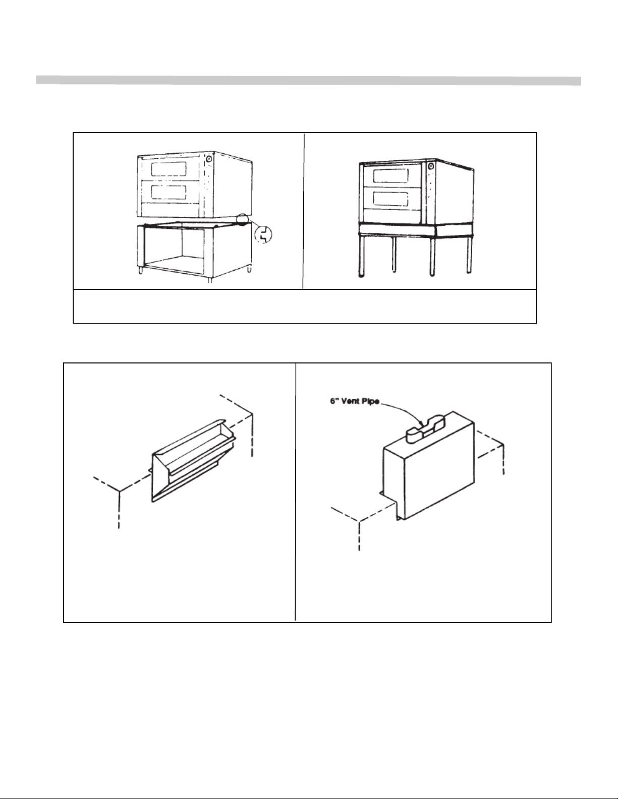
Place oven on stand as shown in Figure 1. Install flue deflector (P/N 16522-0 or 16532
-8) or draft hood (P/N 04391-5 or 04392-3). Either a flue deflector or a draft hood is
shipped with every unit. The flue deflector is intended for use when the oven is installed under a properly designed hood.
When oven is directly connected to vent system, the draft hood must be used. (See
Figure 2 & 6). When oven is in permanent position, level entire unit by placing carpenter’s level on oven rack and adjusting the foot of the bottom of each leg so that oven is
level from front to back and side to side.
5
Page 6
INSTALLATION
Enclosed Base
P/N 16522-0 (Painted) or P/N 16532-8 (S/S)
Flue Deflector
Figure 1
Modular Stand
P/N 4391-5 (Painted) or 4392-3 (S/S)
Draft Hood
Figure 2
6
Page 7
INSTALLATION
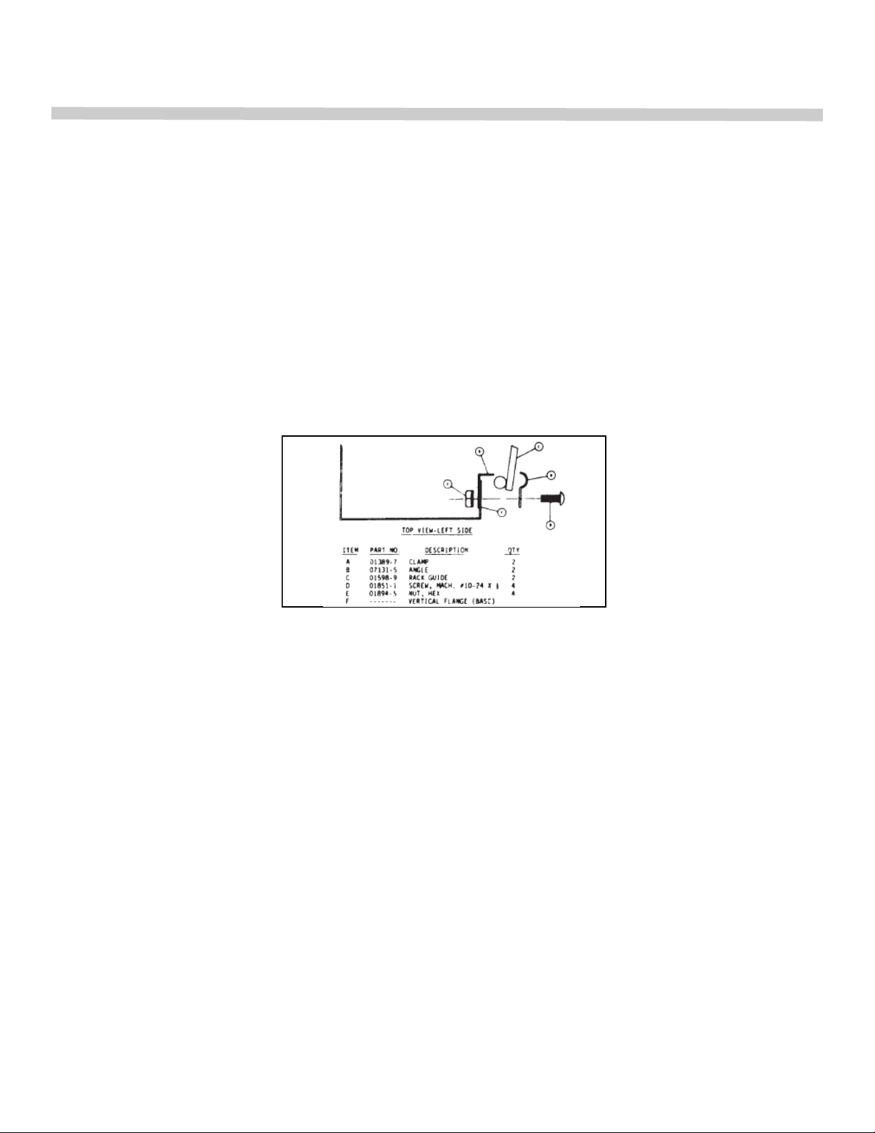
Installation of Rack Guides in Base -Kit No. 04651-5
(If provided See Fig. 3)
1. Set base upright and place on rack guide in position with rod extensions toward rear
and through holes in back.
2. Install stop (B) behind vertical flange forming base opening.
3. Place screw through clamp (A), upper hole of base flange (B) and stop. Install nut.
4. Repeat step 3 with lower hole of flange and stop. Tighten both nuts.
5. Repeat step 2, 3, and 4 for installation of other rack guide on opposite side.
Figure 3
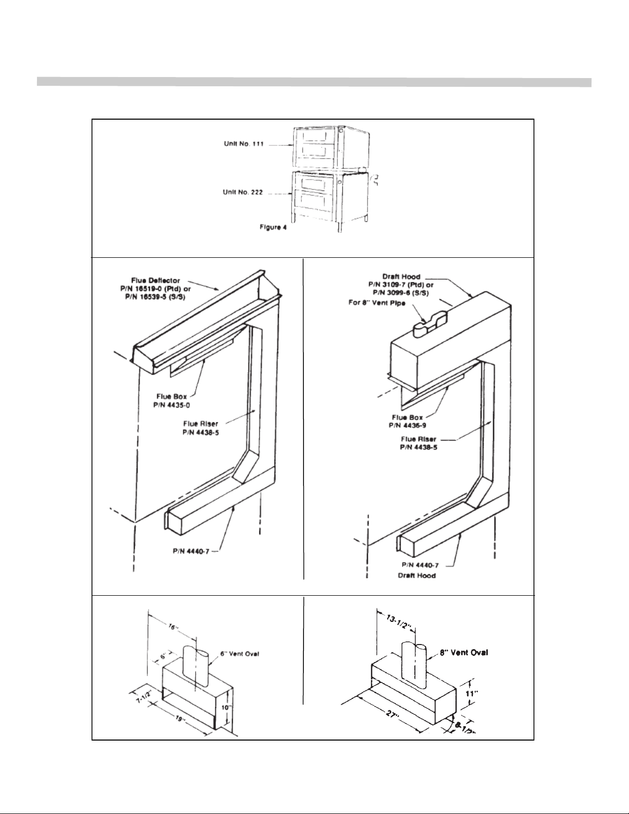
Vectaire Models 2-70, 2-115, SE2-70 & SE2-115 Series (Fig. 4 & 5)
1. Screw the adjustable feet of the legs in all the way. Then tightly screw the complete
leg assembly into the mounting holes at each corner of the lower dock (note logs on
top of lower deck). If unit is intended for curb mounting, Toe Base (P/N:6024-0)
must be used. The Toe Base is factory installed when curb mount is specified.
2. Set upper deck unit in place on top of lower deck.
3. Install flue riser (P/N:25128-3) over outlet of the horizontal flue collector (P/N:25135-
6) of the lower deck. Secure in place with the screws that are provided. Install flue
deflector (P/N:25328-6) over flue outlet of top oven section.
4. Install low profile deflector trim (P/N:26604-3) or draft hood (P/N:24678-6). Either a
flue deflector or a draft hood is shipped with every unit. The flue deflector is intended for use when the oven is installed under a properly designed hood. When the
oven is directly connected to the vent system, the draft hood must be used.
5. When oven is in permanent location, level entire unit by placing a carpenter’s level
on the oven rack and adjusting the foot on the bottom of each leg, so that the oven
is level from front to back and side to side. Level a curb mounted unit by placing a
shim under the slow side.
7
Page 8
INSTALLATION
Figure 4
Figure 5
Figure 6
8
Page 9
INSTALLATION
GAS CONNECTION
Before connecting oven to the gas supply line, be sure that all new piping has been cleaned
and purged to prevent any foreign matter from being carried into the controls by the gas. In
some cases, filters or drops are recommended. A separate gas shutoff valve must be installed
upstream from the gas pressure regulator adjacent to the oven and be located in an accessible area.
It is important that adequately sized piping be run directly to the point of connection at the
oven, with as few elbows and tees as possible. Consult local gas company for proper piping
size and gas pressure.
Each oven is equipped with an appliance gas pressure regulator. This gas pressure regulator
is factory adjusted for the manifold pressure specified on the name plate.
THIS OVEN IS DESIGNED FOR USE WITH A GAS PRESSURE REGULATOR. THE
REGULATOR SUPPLIES WITH THIS UNIT MAY BE USED.
For Natural Gas: This pressure regulator is factory adjusted for 3.5‖- W.C. manifold
pressure. The maximum inlet pressure to the regulator should not exceed 10.5‖ water column.
For Propane Gas: This gas pressure regulator is factory adjusted for 10‖ W.C. manifold
pressure. The maximum inlet pressure to the regulator should not exceed 21‖ water column.
Connect the gas supply line from the service gas shutoff valve to the inlet side of the gas
pressure regulator using 3/4‖ pipe. If flexible or semi-flexible connectors are used, an AGA
Listed flexible connector with an I.D. equal to 3/4‖ pipe must be used. DO NOT USE A
DOMESTIC APPLIANCE TYPE GAS FLEXIBLE CONNECTOR. Avoid kinks or sharp bends
that could restrict gas flow.
PIPE JOINT COMPOUND OR THREAD SEALANT THAT IS USED SHOULD BE
RESISTANT TO ACTION OF LIQUEFIED PETROLEUM GASES.
Turn gas shutoff valve ―ON‖ and immediately check carefully for gas leaks. Do this before
attempting to operate the oven.
TEST ALL PIPE JOINTS FOR LEAKS BEFORE OPERATING OVEN. THIS INCLUDES ALL
GAS CONNECTIONS THAT MAY HAVE LOOSENED DURING SHIPMENT. USE A RICH
SOAP SOLUTION (OR OTHER ACCEPTED LEAK TESTER) AROUND ALL PIPE CONNEC-
TIONS AND ALL OTHER JOINTS. DO NOT USE AN OPEN FLAME. ABSOLUTELY NO
LEAKAGE SHOULD OCCUR, OTHERWISE THERE IS A DANGER OF FIRE OR
EXPLOSION DEPENDING UPON CONDITIONS. NEVER USE IF LEAKAGE IS DETECTED.
9
Page 10

INSTALLATION
Model R85 (Refer to Fig. 2, p. 4)
Uncrate oven and base as near to final location as possible. Remove all packing material
and accessories from oven interior. With help from at least two other people, tip the oven slowly
on its side. With the oven lying on its side, hold the front leg securely and align the threaded
stud on the leg with the nut located at the front corner of the accessible side. Insert the leg into
the nut and turn the leg clockwise. Tighten the leg to the oven securely. Rotate the leg counterclockwise slightly to align the two leg plate holes with the holes on the bottom of the oven.
Secure the leg using the provided 3/8‖ bolts and washers. Repeat the procedure for the rear
corner of the side off the ground. Tip the oven up on the secured legs and lean the oven
against a wall so that the legs on the remaining side can be attached. Install the remaining two
legs using the aforesaid procedure. Tip the oven back down on the newly installed legs and
re-tighten all the bolts securely.
A flue detector is supplied in Kit RS1 with the gusset legs. A Draft Hood is also available
as Kit RS2, and replaces the flue deflector. Either a flue deflector or a draft hood must be
installed on the unit. The flue detector is intended for use when the oven in installed under a
properly designed hood. When the oven is directly connected to a vent system, the draft hood
must be used.
When the oven is in permanent position, level entire unit by placing a carpenter’s level
on the oven rack and adjusting the foot on the bottom of each leg so that the oven is level from
front to back and side to side.
Model R2-85 Series (Refer to Figs. 4, 5 & 6, p. 6)
Screw the adjustable feet of the legs in all the way. Then tightly screw the complete leg
assembly into the mounting holes at each corner of the lower R85 unit. Mount lugs on top of the
lower R85 unit, as to center the top unit on the lower one.
Set upper deck unit in place on top of lower deck.
From Kit RD1, locate the flue riser, the flue collector, and the flue deflector. Install the
flue collector over the flue outlet on the lower R85 unit. Install the flue riser over the outlet of the
horizontal flue collector. Secure in place with self-drilling sheet-metal screws. Install the flue
deflector over the flue outlet of the upper R85 unit. This setup is intended for use when the
oven is installed under a properly designed hood. Note: When the oven is to be directly connected to a vent system, Kit RD2 must be used in conjunction with Kit RD1. Replace the flue
deflector with the Draft Hood ensuring that it covers the flue outlet of the upper R85 unit. It must
cover the top of the flue riser as well.
When the oven is in permanent position, level entire unit by placing a carpenter’s level
on the oven rack and adjusting the foot on the bottom of each leg, so that the oven is level from
front to back and side to side.
10
Page 11
OPERATION
GAS CONTROL SYSTEM—All Models Except with Suffix ―EI‖
Lighting
Turn on main gas shutoff valve and electrical service.
IN THE EVENT A GAS ODOR IS DETECTED, SHUT DOWN UNITS AT MAIN SHUTOFF
VALVE AND CONTACT THE LOCAL GAS COMPLANY OR GAS SUPPLIER FOR SERVICE.
1. Turn oven burner valve clockwise to ―OFF‖ position.
2. Remove burner compartment access panel below oven doors by pulling bottom panel
outward to disengage panel catches.
3. Press and hold red safety pilot in and apply lighted match to pilot burner. After pilot burner
ignites, continue to hold red button depressed for 30-45 seconds or until pilot remains
burning when button is released.
4. Replace burner compartment access panel.
5. Set thermostat to desired temperature.
6. Turn oven burner valve counterclockwise to ―ON‖ position.
7. Turn on fan. Fan should be on at all times during cooking operation.
Shut Down
1. Stand By
a. Turn oven burner valve to ―OFF‖ position.
b. Turn off fan.
2. Complete
a. Turn all gas valves to ―OFF‖ position
b. Turn fan off.
c. Turn electrical service off of disconnect electrical supply cord from wall receptacle.
Relighting
1. Turn oven burner valve to ―OFF‖ position.
2. Wait five (5) minutes then follow ―Lighting‖ instructions.
11
Page 12

OPERATION
GAS CONTROL SYSTEM—Models With Suffix ―EI‖
(Equipped with electronic ignition system)
Operation
1. Turn manual valve to ―ON‖ position.
2. Set thermostat to desired temperature.
3. Push toggle of Start/Reset switch to ―UP‖ position and release. The electronic pilot ignition control
will automatically light the pilot and burner each time the thermostat calls for heat.
4. If pilot fails to ignite within 30 seconds, a complete shut down of the ignition system will occur. To
initiate a re-ignition, wait at least 30 seconds, push toggle of Start/Reset switch up, then release.
Shut Down
1. Turn manual valve to ―OFF‖ position.
2. Turn thermostat to lowest setting.
CAUTION
DO NOT ATTEMPT TO LIGHT THE PILOT MANUALLY WITH A MATCH. THIS COULD RESULT IN THE
MAIN VALVE BEING ENERGIZED IMMEDIATELY.
CONTROLS
Standard Models—Models With Suffix ―AE, AG, ZE, ZG‖
1. ―LIGHT-OFF‖ switch controls the oven interior lights.
2. ―FAN-OFF-COOL‖ switch controls the fan operation. It must be on to obtain satisfactory
performance.
a. The center position is ―OFF‖
b. Depressing ―FAN‖ side of switch causes the motor to run continuously when doors are
closed. When doors are opened, fan will stop. This position is for cooking.
c. Depressing ―COOL‖ side of switch will result in continuous blower operation even with
doors open. This position is intended for cooling the oven at the end of work period or
lowering oven temperature.
NOTE: When cooling oven down, the burner valve should be turned off to prevent burner
operation.
3. The thermostat controls the oven temperature. The ―BURNER‖ indicator light remains lit until
desired oven temperature is reached.
4. The timer is only a time reminder. It has no control over the oven.
12
Page 13
OPERATION
Models With Suffix ―EI‖
Same as ―Standard Models‖ above except for ―START/RESET‖ switch for the electronic ignition
system. Depress switch momentarily at the start of the work period.
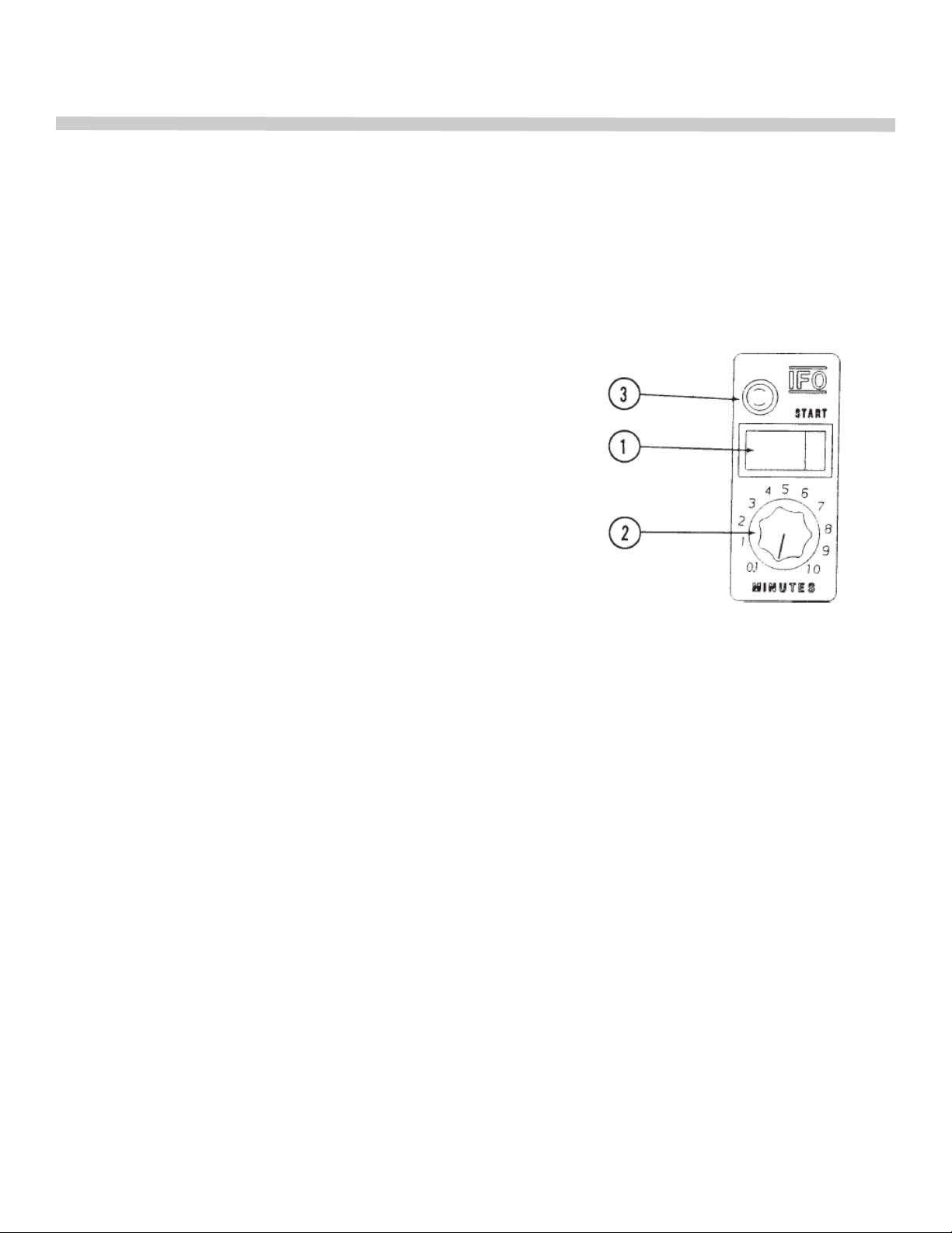
INTERMITTENT FAN OPERATION (IFO) CONTROLS (Optional)
The IFO fan control cycles the fan ON for 30 seconds and OFF for 30 seconds during a variable
time of 0.1 to 10 minutes of the cook period.
IFO Control
1. START SWITCH (MOMENTARY)
Activated the IFO cycle.
2. CYCLE TIMER (0.1 TO 10 MIN.)
Controls the duration of the IFO cycle.
3. INDICATOR LIGHT (AMBER)
When lighted, indicates the oven is in the IFO cycle.
IFO Operation
To set the IFO controls, first set the ―Cycle Timer‖ knob for the desired IFO time period. Once the
oven has reached temperature, load the product to be baked and close the door. Immediately set
and start the standard timer for the overall cook cycle. Next, push the ―Start‖ switch on the IFO
control. The amber indicator light will come on, the fan will stop, and then cycle on and off every
30 seconds until the set time has expired. The amber light will remain on continuously until the set
time has expired.
Once the amber light is on, additional pushing of the ―Start‖ switch will have no effect. Also the
―Cycle Timer‖ knob does not count down during the IFO cycle, but remains at its setting for
repeat cycle if desired.
To cancel the IFO cycle once started, simply rotate the ―Cycle Timer‖ knob counterclockwise until
it stops.
Once started, the IFO time period can be readjusted by simply repositioning the ―Cycle Timer‖
knob. If the knob is turned counterclockwise to a setting that is less than the current time expired
during the cycle, the cycle will be terminated. To restart a cycle, simply push the ―Start‖ switch.
If it is necessary to open the door during the IFO cycle, the fan will shut off if it is running. The IFO
timed cycle will continue uninterrupted, however, until the set time has expired. If there is a loss of
power during the cycle, it will be terminated.
13
Page 14
OPERATION
OPERATION
MOIST AIR CONTROLS & OPERATION (optional)
Moist Air (Steam) Option
The Moist Air option permits the operator to add steam to the oven chamber during the cooking cycle.
This is desirable during baking operations for crusting purposes or to maximize growth during the initial
bake period. It can also be useful for products requiring more moisture during the cook cycle.
Moist Air Components
The Moist Air option includes a water shut-off valve, water regulator/filter assembly, solenoid valve,
steel piping, spray nozzle, steam pan and Moist Air control cluster. During operation, activating controls
causes the solenoid valve to open and heated water to be sprayed into the hot oven chamber where it
is turned into steam. The steam pan converts any excess spray to steam and controls residue accumulation.
INSTALLATION
ATTENTION!
The Moist Air option requires a connection to good quality water that is low in total dissolved
solids and free of particulate matter. A water purification/treatment system must be installed if
harsh water conditions exist. If in doubt, have your water supply checked by a water treatment
company.
The water regulator filter assembly with shut-off valve (supplied with the Moist Air option) should be
wall mounted near the oven so that the four foot removable hose will reach the water connection on
the back of the oven. A permanent 1/2‖ cold water connection should be made at the shut-off valve.
This filter is meant to remove final traces of taint, odor, rust, and scale when used with good quality
water or a water purification/treatment system. It is not a substitute for a water treatment if harsh water conditions exist.
All other normal installation requirements for a Vectaire convection oven, as described in the
―Installation‖ section of the main Vectaire manual, should be followed.
OPERATION
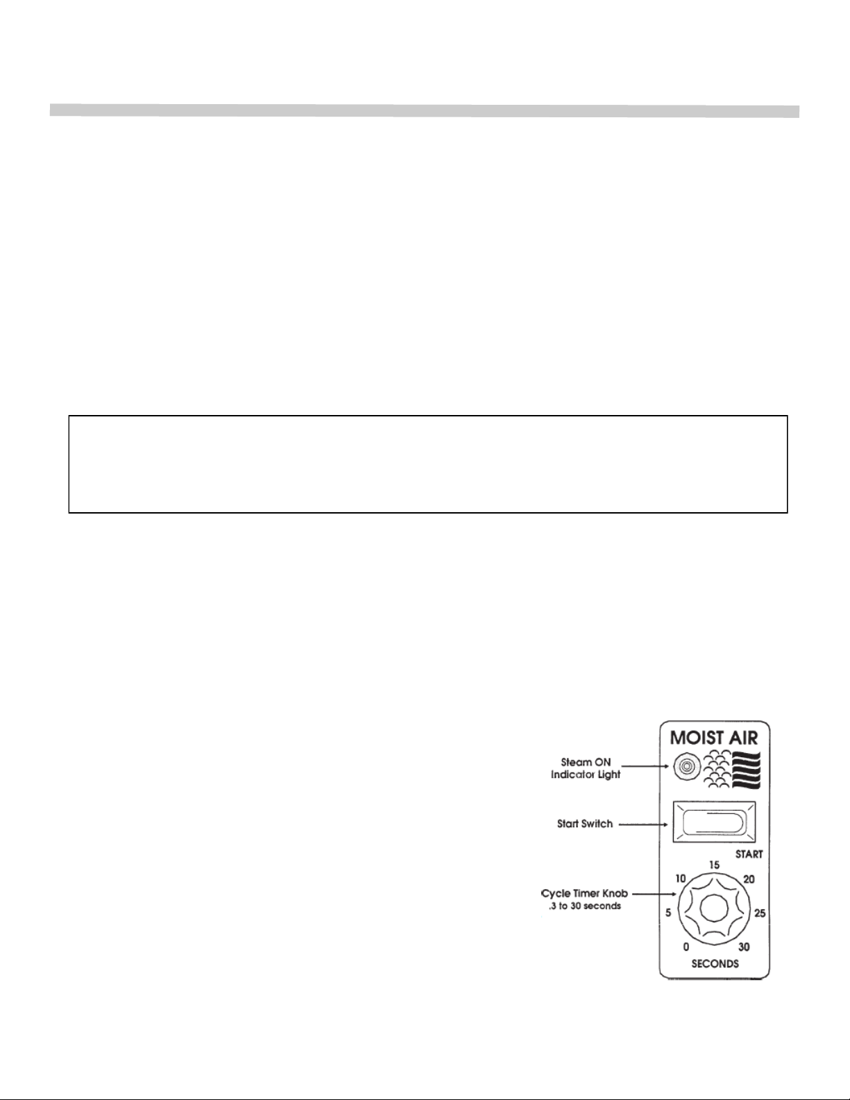
The Moist Air control regulates the spray of water that created
steam in the oven chamber. The duration of the water spray can
be varied from .3 to 30 MOIST AIR seconds. The spray is initiated
by depressing the start switch.
To set the Moist Air controls, first set the ―Cycle Timer‖ knob for
the desired time period. Once the oven has reached temperature,
load the product to be baked and close the door. Immediately set
and start the standard timer for the overall cook cycle. Next, push
the ―Start‖ switch on the Moist Air control. The blue indicator light
will come on, and remain on continuously until the set time has
expired. Steam is being generated in the oven when the light is
on.
Once the blue light is on, additional pushing of the ―Start‖ switch
will have no effect. The ―Cycle Timer‖ knob does not count down, but remains at its setting for repeat
cycle if desired.
14
Page 15
OPERATION
CAUTION
Never attempt to open the oven doors while the Moist Air indicator light is on, and use caution for
at least 5 minutes after the light has gone out. The hot, moist air resulting from the steam
generation could cause serious burns.
Best performance from the Moist Air option is realized at temperatures of 300°F and above. The
Moist Air option is not recommended for use at temperatures below 250°F, and a low-limit control
will not permit activation at temperatures below about 200°F. A full preheat of the oven (1 hour) is
necessary before use. Once at temperature, as many steam cycles can be initiated as desired.
An oven vent control is conveniently located at the top of the control panel. Positioning the lever all
the way to the left closes the vent; to the right opens the vent. For best results, introduce steam
into the oven with the vent closed. After two or three minutes, open the vent to allow the steam to
escape and leave open for the remainder of the bake.
MAINTENANCE
Additional maintenance is required with the Moist Air option to insure trouble-free operation.
The filter cartridge should be replaced every 4-6 months. This can be easily done by closing the
water valve, then loosening the thumb screw at the bottom of the filter bracket.
The spray nozzle is located inside the oven behind the fan baffle. With the fan baffle removed, the
spray nozzle can be removed and disassembled for cleaning. The fine mesh monel screen should
be carefully cleaned with air pressure to remove debris and scale deposits. The grooved distributors inside the nozzle housing should be removed and both pieces checked with a wire to be
certain they are free from any build-up of scale or sediment. Reassemble the nozzle and install.
This should be done every 1-3 months depending on water conditions.
The oven interior should be cleaned daily with warm soapy water to discourage the build-up of
deposits. The use of an abrasive is not recommended.
SERVICE
If the Moist Air option requires service or becomes inoperative, contact the local Authorized
Service Agency.
15
Page 16
COOKING HINTS
COOKING HINTS
USING A CONVECTION OVEN
The convection oven is a different type of oven which offers many features and advantages to
the food service operation. The operation of the oven is not difficult to understand or control.
The convection oven is the sealed type whereby the combustion products are separated from
the air inside the oven. The heat is transferred through the oven surface into the cavity. The
air inside the oven is continuously recirculated over the heat source and the product.
The moving air strips away the insulating layer of moisture on the products allowing heat to
penetrate faster for quicker baking and roasting. Due to these differences in the methods of
cooking in a convection oven, procedures and techniques may require some modification for
successful results. A general rule which will assist in better operation, is cooking time will be
less and temperatures should be 25 to 75 degrees lower than those called for in standard
recipes.
For convection oven cooking, reduce temperature 25 to 75 degrees from those
given in standard recipes.
Type of Food Reduction in Reduction in
Temperature Time
Baked Products
Cookies 25° 1/4 to 1/3
Cakes & Quick Bread 50° 1/4 to 1/3
Yeast Products 75° 1/4 to 1/3
Casseroles 25° 1/4 to 1/2
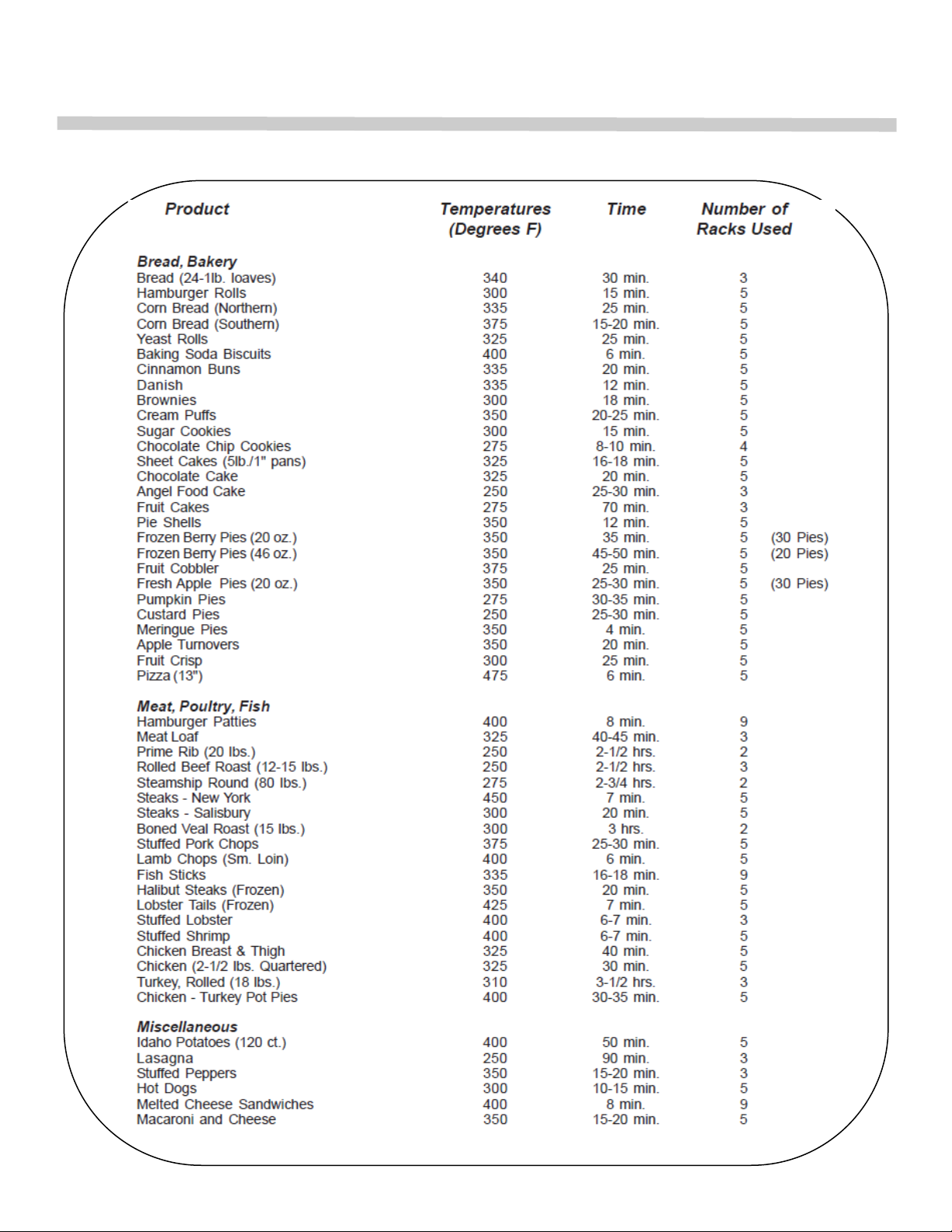
GUIDE TO BAKING TIMES AND TEMPERATURES
These times and temperatures were especially prepared and tested for use in a Vectaire
convection oven. Times, temperatures, and moisture contents may vary in other convection
ovens. The suggested times and temperatures may vary considerably from those shown.
They are affected by weight of load, recipe, type of pan, size of portion, and calibration of
thermostat. Differences in quality and age of meats and fowl, and quantities of shortening,
milk, fat, and other ingredients in baked goods affect both cooking times and temperatures.
These charts have been compiled carefully. However, they are only guides. You may want to
cook certain foods a little more or a little less according to your preference and your recipe.
Also, types and sizes of pans influence baking time and temperatures.
It is absolutely necessary to use lower temperatures. As a guide, set oven temperatures 2575 degrees lower than called for in your recipes using non-convection ovens.
Use this chart as a guide to develop your own cooking techniques.
16
Page 17
COOKING HINTS
Guide to Time and Temperature
17
Page 18

COOKING HINTS
COOKING HINTS
Suggestions
Avoid recipes that would not be satisfactory in a regular conventional oven.
Times and temperatures will vary slightly with maximum to minimum oven loads.
Stagger pans in ovens as much as possible to allow the free flow of air.
Pans may be tightly sealed with sheets of aluminum foil. Do not let the foil touch
the food.
Convection ovens usually save 1/4 to 1/3 of the total cooking time. Check product
at one-half of the cooking time of the recipe. Add additional time as needed.
For most products, use a maximum of 5 racks for optimum results.
For less browning, lower temperature; for more browning, increase temperature. If
product cooks too quickly around the edges, lower temperature.
Level pans bake more evenly than warped pans.
Filling pans too full causes uneven baking.
When using frozen entrées, refrigerator-thaw for best results, and cover during
cooking.
Load and unload food quickly. Close oven doors promptly.
The type of pans used affect baking time and results. A shiny pan reflects heat, a
dark dull pan absorbs heat.
When baking fruit pies, use a baking pan on the rack and set pie tins on top of pan.
This will result in evenly cooked bottoms and also catch spillovers.
Baking Difficulties & Problem Causes
Good baking is a delicate operation and many operational factors enter into it.
Pans which warp or buckle under hear always result in poor bakes. Pans with highly polished
reflecting surfaces generally cause light colored bottom or sides. Muffin tin cups should all
rest on a flat surface, otherwise light or underdone bottoms will result. Pie tines that are
pocked or warped will give undesirable results.
Overproofing, working or dough in too high of a room temperature, overworking pastry dough,
absence of or improper scaling, cutting and uneven loading of pans are sure ways of getting
uneven baking.
18
Page 19

COOKING HINTS
―HIT OR MISS‖ recipe mixing: Guess work in the matter of quality and quantity of ingredients
frequently results in poor bakes.
The following are some baking problems and their probable causes:
Goods Pulled to Rear of Oven
Oven not level. Pitched to rear causes dough to run to rear.
Pans too full. Excess will pull over back toward fan.
Batter has too high a percentage or liquid.
Uneven Bakes
Insufficient heat input.
Warped pans.
Warped oven racks.
Uneven loading of pan or pans.
Fan off.
Oven not level causing dough to run to side or rear of pan.
Spotty Pie Bottoms/Bread
Overworked pastry/dough.
Burned Goods, Cripples
Incorrect temperature.
Thermostat out of calibration.
Left in too long.
Improper scaling.
Dried Out Goods
Too low temperature.
In oven too long.
Improper mix.
Alternately Good and Poor Results
Fan off and on.
Improper scaling and control of ingredients.
Tops Dark, Center Not Done
Too high temperature.
Side Burning
Oven not level.
Uneven loading.
19
Page 20

COOKING HINTS
Lack of Uniformity—Same Pan
Uneven loading in pan. (See uneven bakes).
Faulty pans.
Lack of Spring
Overproofing.
Incorrect temperature.
Cracked Cakes
Too high temperature
Too fast cooling.
Underdone Pie Bottoms (Advisable to bake on cookie sheet)
Pastry too rich.
Pastry too thick.
Warped pie tins. (When used on cookie sheet)
Heavily Colored Pie Rims
Air bubbles enclosed in pastry when crimped.
Uneven Baked Cookies
Not scaled properly.
Pans warped.
20
Page 21

MAINTENANCE
MAINTENANCE
CAUTION
DISCONNECT POWER BEFORE CLEANING OR SERVICING. EACH OVEN SECTION HAS
A SEPARATE ELECTRICAL SUPPLY CONNECTION.
General Cleaning
The complete oven should be given a periodic cleaning. Lint and grease suspended in the air tend to
collect in air passages.
Remove burner compartments access panel and clean any dirt and lint from burner primary air
opening and all air passages and openings. Clean lint and grease accumulation from motor air
openings.
Exterior
PAINTED SURFACE: Allow equipment to cool after use and wash with a mild detergent or soap solution. Dry thoroughly with a dry cloth.
STAINLESS STEEL SURFACES: Follow instructions in Stainless Steel section.
Oven Interior
STANDARD FINISH (Porcelain Enamel): Frequent cleaning is required. Spillovers should be cleaned
as soon as possible to prevent carbonizing and a burnt-on condition. Wait until oven is cool for
complete cleaning. Usually a soap or detergent solution is strong enough to remove any grease residue. A mild abrasive nylon cleaning pad may be used for stubborn spillovers or stains. Non-caustic
commercial oven cleaners may be used, but do not allow cleaners to come in contact with the temperature probe. Wipe off all oven cleaner residue.
The racks and rack guides are readily removable for cleaning. Loosen retainer clips to disengage
rack guides for removal.
Foreign matter may collect on the fan blades and reduce circulation. When this becomes apparent,
remove the fan baffle plate which is secured by 4 thumb screws and pull plate up and forward. The
use a stiff brush on each fan blade.
CONTINUOUS CLEAN FINISH: It is readily identified by its dark brown and white speckled finish.
This coating is endowed with a unique cleaning ability that causes food and grease spatters to
gradually clean away automatically when exposed to normal oven temperatures.
Each day, after baking and roasting operations have been completed, empty the oven. Then turn the
temperature control up to high heat. This high heat will speed up the cleaning action and reduce the
time required to clean the oven effectively. The cleaning time necessary will depend up on the ―soil‖
condition the oven. As a general rule, allow from 45 to 60 minutes.
When the oven appears soiled due to heavy staining, we suggest preheating the empty oven each
day for one or two hours for most effective results. Also, ordinary household ammonia has proved an
effective method for removing baked-on build-up, and in keeping the microscopic pores of the
coating open and free to perform its cleaning action. Thus, an occasional light swabbing with household ammonia while oven is at room temperature can prove to be extremely beneficial.
21
Page 22

MAINTENANCE
MAINTENANCE
Excessive spillage or crust which is allowed to build up on oven interior surfaces will seriously
retard the continuous cleaning action. It should be wiped away as soon as possible with a
damp cloth.
Although the oven may appear clean, we recommend operating the oven at high heat for
approximately two hours once every month. This will prevent build-up of solids in hard-to-see
places or in the pores of the coating. Caution: Never use abrasives, powders, harsh liquids,
caustics, or dyes as they may leave a film or residue that will clog the pores of the special
coating, and retard the cleaning action.
Certain types of food may leave a stain that is slow to fade. These include flour-milk mixtures,
sugar, macaroni and cheese, cream sauces, and blood. It may take a slightly longer time for
the continuous cleaning action to clean this type of stain. Accelerate removal by using household ammonia while oven is at room temperature.
If excessive soils or spillovers have become carbonized, remove the charred potion with a hard
nylon brush. (Do not use steel or other metallic brushed or scouring pads). For any stubborn
stain or ―varnish‖ film, apply a good grade paste oven cleaner in the following manner:
(1) With the oven at room temperature, apply paste over the spill.
(2) Allow to stand for 10-15 minutes (read instructions on label of product); then wipe up spill.
(3) Reapply if not entirely removed (any film remaining over top of material will prevent self-
cleaning action).
(4) Remove loosened particles with a damp cloth. Note: Steam may be used where it is
available. It is not harmful to the special coating. Always be sure to wipe up any excess
water.
STAINLESS STEEL: To remove normal dirt, grease, or product residue from stainless steel,
use ordinary soap and water (with or without detergent) applied with a sponge or cloth. Dry
thoroughly with a clean cloth.
To remove grease and food splatter, or condensed vapors that have baked on the equipment,
apply cleanser to a damp cloth or sponge and rub cleanser on the metal in the direction of the
polished lines on the metal. Rubbing cleanser as gently as possible in the direction of the
polished lines will not mar the finish of the stainless steel. NEVER RUB WITH A CIRCULAR
MOTION. Soil and burnt deposits which do not respond to the above procedure can usually be
removed by rubbing the surface with SCOTCH-BRITE scouring pads or STAINLESS scouring
pads. DO NOT USE ORDINARY STEEL WOOL as any particles left on the surface will rust
and further spoil the appearance of the finish. NEVER USE A WIRE BRUSH, STEEL
SCOURING PADS (EXCEPT STAINLESS, SCRAPER, FILE, OR OTHER STEEL TOOLS.
Surfaces which are marred collect dirt more rapidly and become more difficult to clean. Marring
also increases the possibility of corrosive attack.
22
Page 23
MAINTENANCE
TO REMOVE HEAT TINT: Darkened areas sometimes appear on stainless steel surfaces
where the area has been subjected to excessive heat. These darkened areas are caused by
thickening of the protective surface of the stainless steel and are not harmful. Heat tint can
usually be removed by the foregoing, but tint which does not respond to this procedure calls for
a vigorous scouring in the direction of the polish lines, using SCOTCH-BRITE scouring pads or
a STAINLESS scouring pad in combination with a powdered cleanser. Heat tint action may be
lessened by not applying or by reducing heat to equipment during slack periods.
Electric Fan Motor
The customized electric fan motor has been specially manufactured for this application and
should under normal conditions give years of trouble-free service.
The unit is supplied with permanently lubricated sealed bearings which require no additional
lubrication. A high temperature grease has also been used to increase bearing life and should
only be replaced by an authorized service station.
The motor is equipped with a built-in thermal overload protector which will warn of any over
heating.
The motor is of an open drip-proof type construction, and as such, care should be given to see
that the ventilation openings remain clear.
If problems do develop with the motor, contact your nearest authorized service station, do not
attempt repairs yourself. This is a special piece of equipment and should only be serviced by
competent persons familiar with the construction.
CAUTION:
CARE SHOULD BE USED WHEN WASHING DOWN EQUIPMENT TO KEEP WATER
AND CLEANING SOLUTIONS OUT OF THE MOTOR OR DAMAGE WILL OCCUR.
23
Page 24
ADJUSTMENT
Main Burner
While your oven has been factory adjusted, it sometimes happens that the actual operating
conditions are different. Therefore, it may be necessary to make a field adjustment to
secure satisfactory performance. The air adjustment should give a medium sharp flame
without lifting or flashback. Air shutter is adjusted by loosening thumb screw and sliding air
shutter left or right. Tighten thumb screw after adjustment. The R85 sheet metal burner has
two air shutters, one for each burner tube.
The orifice on the manifold is the fixed type, sized for the respective gas supply.
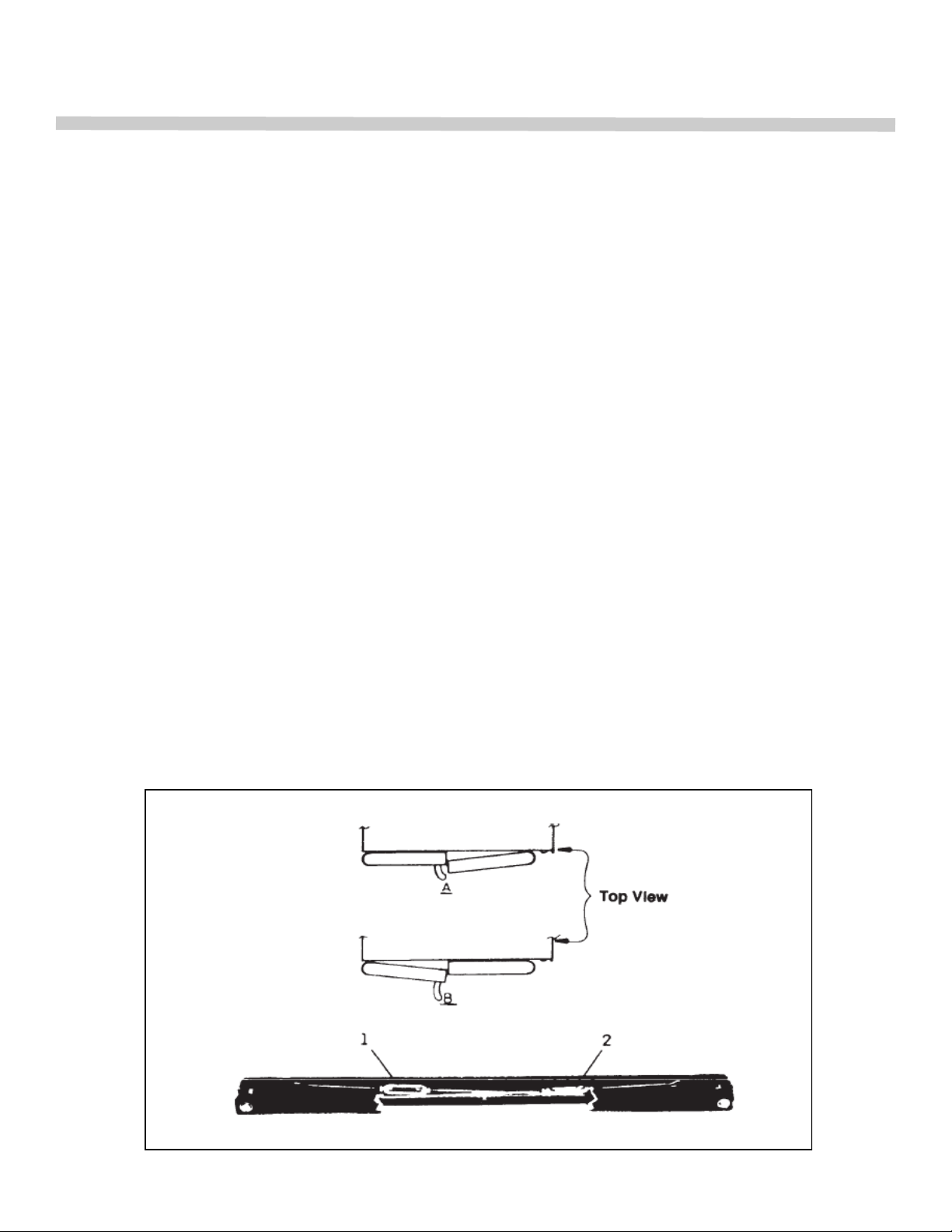
Door Adjustment
Procedure:
1. Right hand door on oven does not close when left hand door closes. Loosen turnbuckle
―1‖ and tighten turnbuckle ―2‖.
2. Left hand door on oven does not close when right hand door closes. Loosen turnbuckle
―2‖ and tighten turnbuckle ―1‖.
Note: Half turn on turnbuckle equals approximately 1/2‖ adjustment. When through
with adjustment, both turnbuckles should be left flat so as to clear front fire box
panel.
24
Page 25
ADJUSTMENT
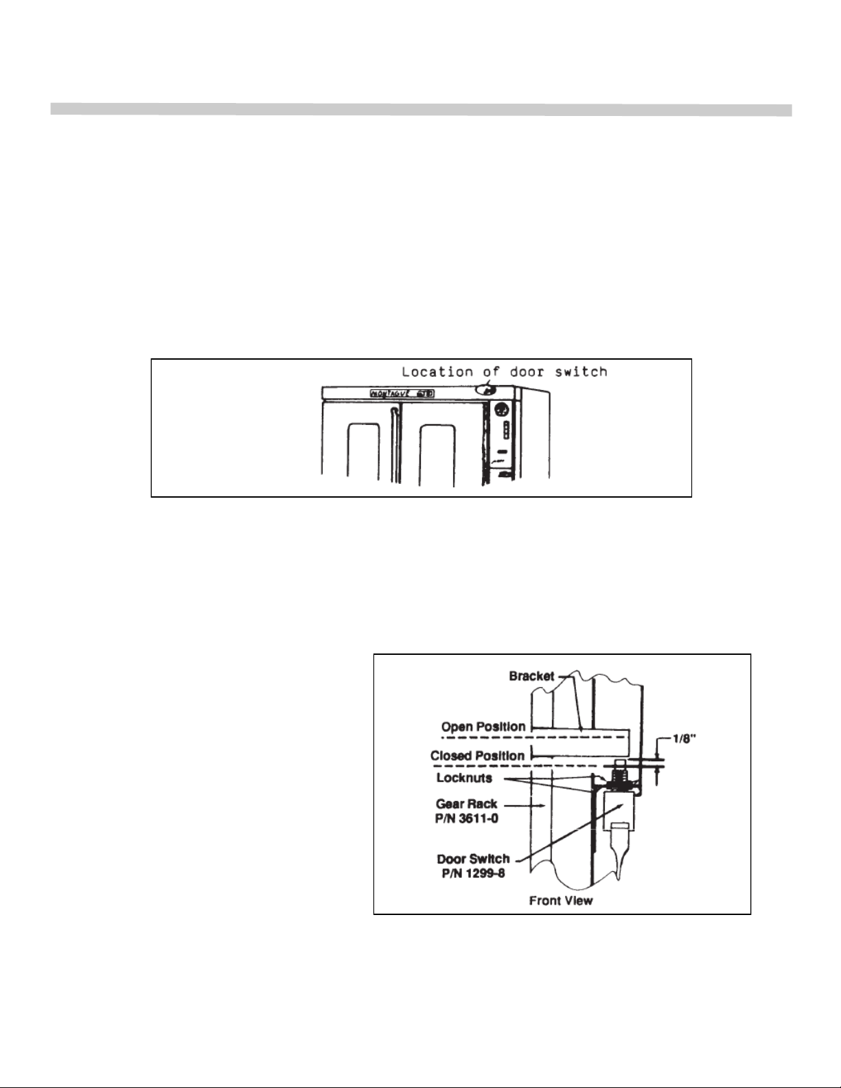
DOOR SWITCH ADJUSTMENT—Models With Suffix ―A‖
Door switch can only be adjusted by bending switch lever with pliers.
Procedure:
1. Remove upper front trim panel for access to switch.
2. Bend switch lever with pliers so that fan will stop when door is opened between 9 and
10 inches.
DOOR SWITCH ADJUSTMENT—Models with suffix ―Z‖
Before adjusting door switch, make sure fan switch is in ―fan‖ instead of ―cool‖ position.
Electrical circuit in ―cool‖ position bypasses door switch.
Procedure:
1. Disconnect electrical power supply.
2. Remove upper and lower control
panels.
3. Loosen top locknut on door switch.
4. Raise or lower bottom locknut so
that when the door is closed, the
plunger on the switch is depressed approximately 1/8‖.
5. Tighten top locknut.
6. Replace both control panels.
25
Page 26
SERVICE
WHEN SERVICE IS NEEDED, CONTACT A LOCAL SERVICE COMPANY, DEALER, OR
FACTORY TO PERFORM MECHANICAL MAINTENANCE AND REPAIRS. THESE IN-
STRUCTIONS ARE INTENDED FOR USE BY COMPETENT SERVICE PERSONNEL.
CAUTION:
DISCONNECT POWER BEFORE DOING ANY SERVICE WORK. EACH OVEN SECTION
HAS A SEPARATE ELECTRICAL SUPPLY CONNECTION. TURN OFF GAS SUPPLY
WHEN SERVICING GAS CONTROL SYSTEM.
THERMOSTAT ADJUSTMENT
The calibration of the thermostat should not be changed until sufficient experience with
cooking results has proved that the thermostat is not maintaining proper oven temperature.
Before any recalibration is attempted, the oven temperature should be checked using a
good grade thermometer.
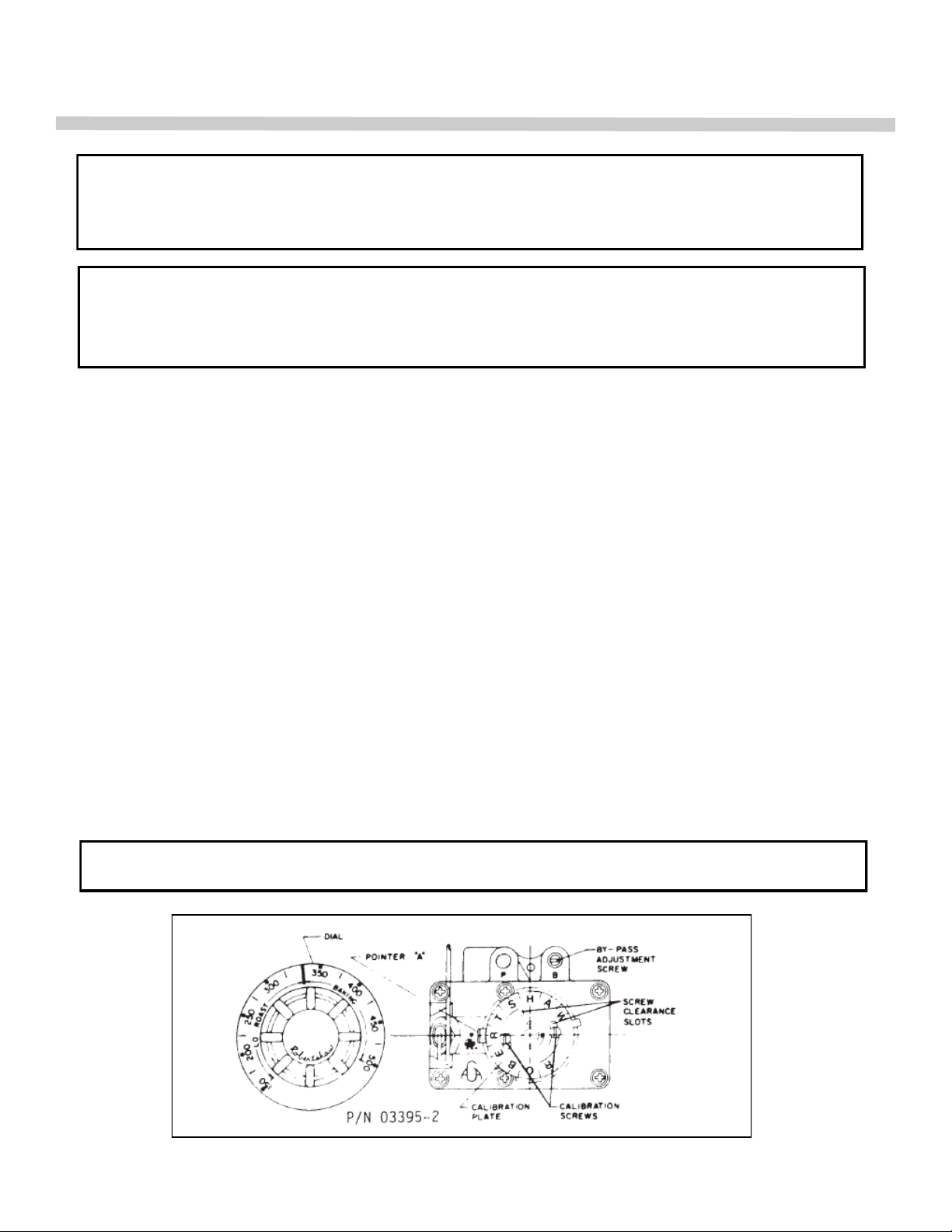
GAS THERMOSTAT—Models with suffix ―G‖
The Model FDO Robertshaw is a combination Snap-Throttle Thermostat. When the dial is
set at a temperature, the thermostat will open wide allowing maximum flame at the burner.
As the temperature begins to rise and reach the temperature setting, the thermostat begins
to throttle the gas, cutting down the burner flame to the amount of gas needed to hold the
oven at the set temperature. If the oven is empty or very lightly loaded, the minimum flame
of the burner will continue to rise. When this happens, the thermostat snaps the minimum
flame off. As the temperature drops, the minimum flame will snap on. It is possible to operate the oven at a low temperature and at the same time give you the advantage of a
throttling type thermostat.
By-Pass (Minimum Burner Flame)
THIS ADJUSTMENT MUST BE CHECKED AT THE TIME APPLIANCE IS INSTALLED.
26
Page 27
SERVICE
SERVICE
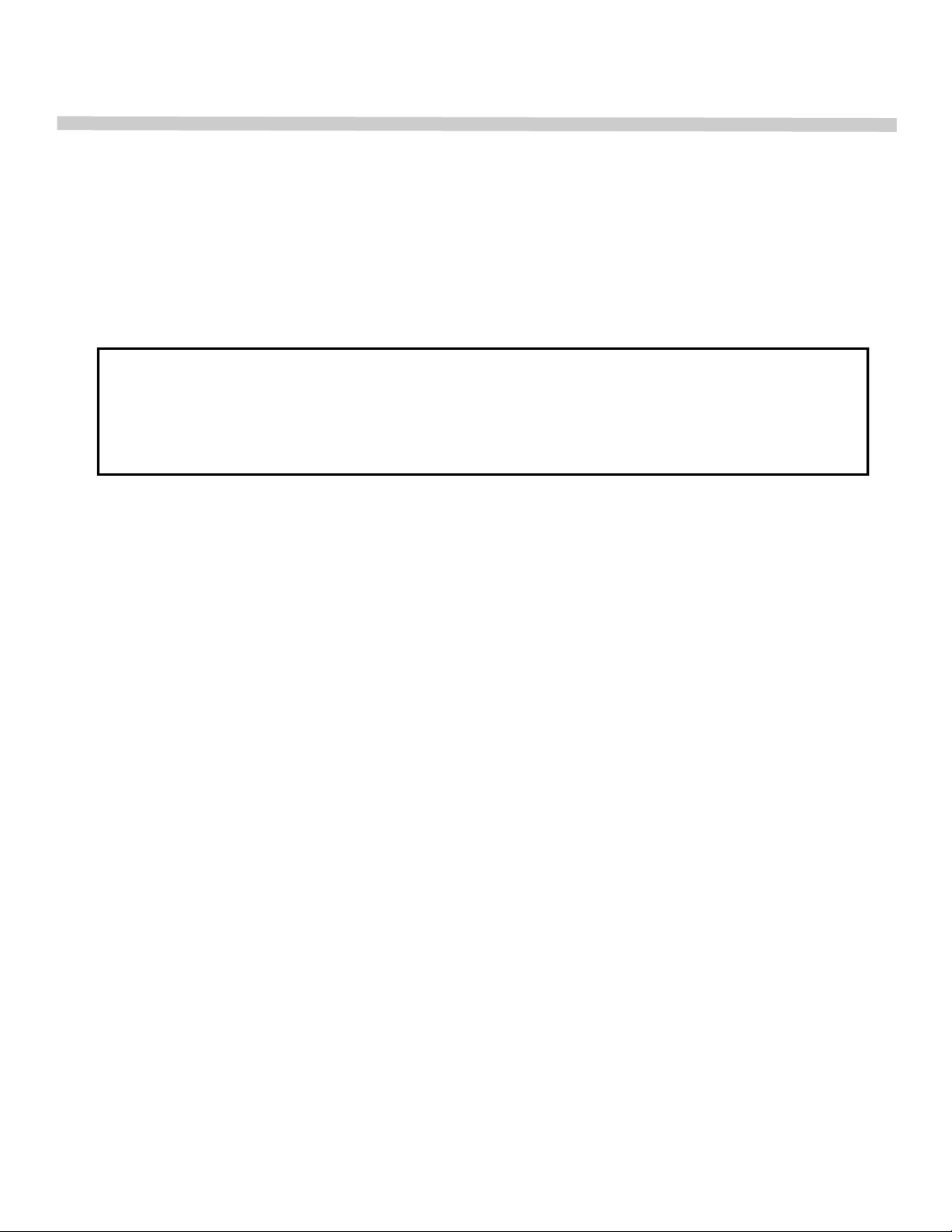
TO ADJUST BY-PASS (Be sure pilot flame is ignited):
1. With oven cold, turn dial counterclockwise slowly from ―Low-Stop‖ until by-pass seat just
snaps on.
2. Remove dial.
3. With a screwdriver, turn ―By-Pass Adjustment Screw‖ (see sketch) counterclockwise to
increase the by-pass flame to clockwise to decrease it until flame over entire burner is
approximately 1/4‖ high.
4. Replace dial.
CAUTION:
While making this adjustment, if the oven should become heated while the dial is set at a
low range (below 350), the bypass flame will shut off completely. If this occurs, turn dial
counterclockwise slowly until by-pass gas valve snaps on. Then check by-pass adjustment
as stated above.
Thermostat Calibration Check:
1. Place the thermocouple of test instrument or thermometer in the middle of the oven, or
medium to be tested.
2. Light the main burner.
3. Turn dial so 400 lines up with ―Pointer A‖ indicator mark.
4. Allow the oven to heat until flame cuts down to by-pass. After sufficient time, check
temperature. If the temperature does not read within 15 degrees of the dial setting,
recalibrate as follows:
5. Pull dial straight off without turning.
6. Hold calibration plate and loosen the two calibration lock screws until the plate can be
moved independently of the control.
7. Turn calibration plate counterclockwise if the test reading is higher than the dial setting, or
clockwise if the reading is lower than the dial setting. The temperature range between each
mark is 25°F (Between each letter is 50°F).
NOTE: If the adjustment is prevented by the two loosened calibration lock screws being in
contact with the ends of the screw clearance slots in the calibration plate, remove the screws
after turning the calibration plate to the proper location, reassemble screws in the other tapped
holes designed for them.
8. Replace dial.
ELECTRIC THERMOSTAT—Models with Suffix ―E‖ & ―EI‖
1. Place a pyrometer thermometer or a reliable mercury oven type thermometer at the center of
the middle rack.
2. Turn the dial of the cook thermostat to a temperature setting of 350°F.
3. The red cook indicating light will switch from ―ON‖ to ―READY‖ when the thermostat turns off
the burner.
4. Allow three (3) such cycles for the temperature to stabilize.
5. Read the pyrometer or thermometer immediately after the ―READY‖ light comes on for the
third time and again immediately after the ―READY‖ light comes on the next time.
6. If the average readings and the dial setting vary by more than 15°F, recalibrate by following
the instructions outlined below.
27
Page 28
SERVICE
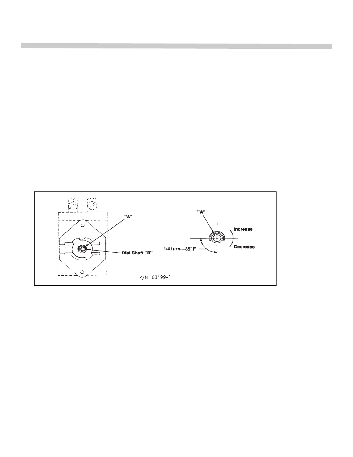
To Recalibrate
1. Remove dial from dial shaft ―B‖.
2. Turn screw ―A‖ clockwise to decrease and counterclockwise to increase the
temperature.
3. 1/4 turn changes the temperature 35°F.
4. Replace dial on dial shaft.
5. After a calibration is made, set the dial at 350°F and recheck the oven
temperature using the method above, outlined by items 1 thru 6.
REPLACEMENT OF OVEN INTERIOR LIGHT BULBS
Disconnect electrical power to oven before servicing. Remove six thumb screws
located at the top and bottom and middle of the fan baffle and pull the panel
forward to expose light sockets.
28
Page 29
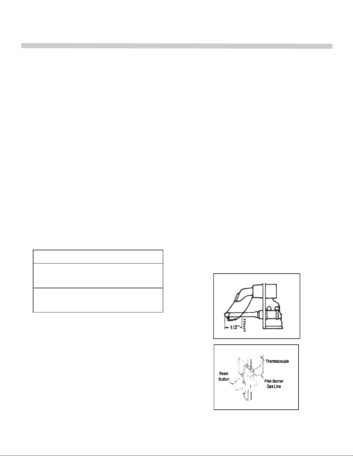
REMOVAL OF MAIN BURNER AND PILOT BURNER
1. Remove burner box panel for access.
2. Turn off gas supply to oven. Remove single screw at front of burner on the left side.
3. Slide main burner to the left until venturi clears orifice and pull main burner and pilot
burner out far enough for access to the pilot burner mounting screws.
4. Remove mounting screws from pilot burner and pull main burner the remainder
of the way out.
NOTE: Special attention should be given to the condition of burner baffle (P/N 04344-3).
Due to the high input rating of this burner, after a period of time, the baffle will burn out.
The burner baffle should be replaced before the flame does any damage to the burner
box top plate located above the baffle.
PILOT SERVICE IN THE EVENT OF PILOT FLAME FAILURE
1. If pilot flame burns yellow, clean pilot orifice and pilot burner to insure a steady
blue flame. The orifice can be cleaned by washing in a solvent and/or blowing
out with air.
2. Flame must surround the thermocouple tip for approximately ½ inch
THERMOCOUPLE OUTPUT
OPEN CIRCUIT
MV RANGE
NORMAL NOT LESS THAN
25-35 17
SAFETY PILOT VALVE
Model H15HQ-5 BASO is an automatic 100%
safety pilot which provides complete gas shut
off in the event of pilot failure. The safety valve
is half closed by spring pressure. When red button
is pushed by hand, gas flows to pilot. Pilot heats
thermocouple creating a very small amount of
electricity. This energizes a magnetic coil under
red button and holds valve open, permitting gas
to flow to main burner and pilot without holding
pressure on red button. In the event of pilot failure,
the flow of electricity will stop and spring will stop
flow of gas to both pilot and main burner.
SERVICE
29
Page 30
SERVICE
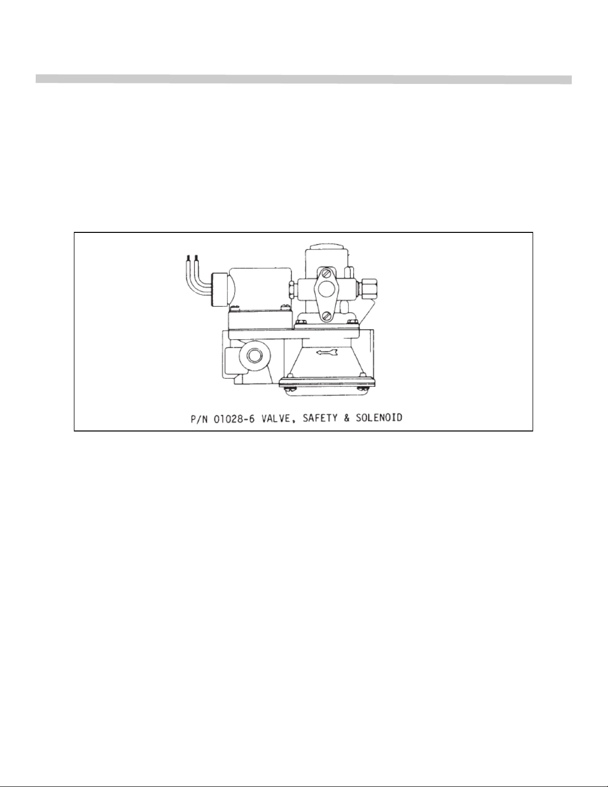
COMBINATION SAFETY PILOT VALVE & AUTOMATIC GAS VALVE
Safety Pilot Valve Section
The 100% safety shutoff valve operates from millivoltage produced by a thermocouple
properly heated by the pilot flame. In the event of a low, unstable pilot flame or outage,
the safety valve provides complete gas shutoff. The safety valve is held closed by
spring pressure. When red button is depressed by hand, gas flows to pilot. The pilot
flame heats the thermocouple creating a small amount of electricity. This energizes the
magnetic coil under red button and holds valve open as long as thermocouple is heated, permitting gas to flow to main burner and pilot. In event of pilot failure, the flow of
electricity will stop and spring pressure will close valve shutting off flow of gas to both
pilot and main burner.
30
Page 31
SERVICE
CHECKOUT PROCEDURE
BEFORE LEAVING THE INSTALLATION, A COMPLETE OPERATING CYCLE SHOULD BE
OBBSERVED TO SEE THAT ALL COMPONENTS ARE FUNCTIONING PROPERLY.
GAS PRESSURE REGULATOR
WARNING
NO UNTRAINED PERSON SHOULD ATTEMPT TO MAINTAIN OT SERVICE THE GAS
PRESSURE REGULATOR
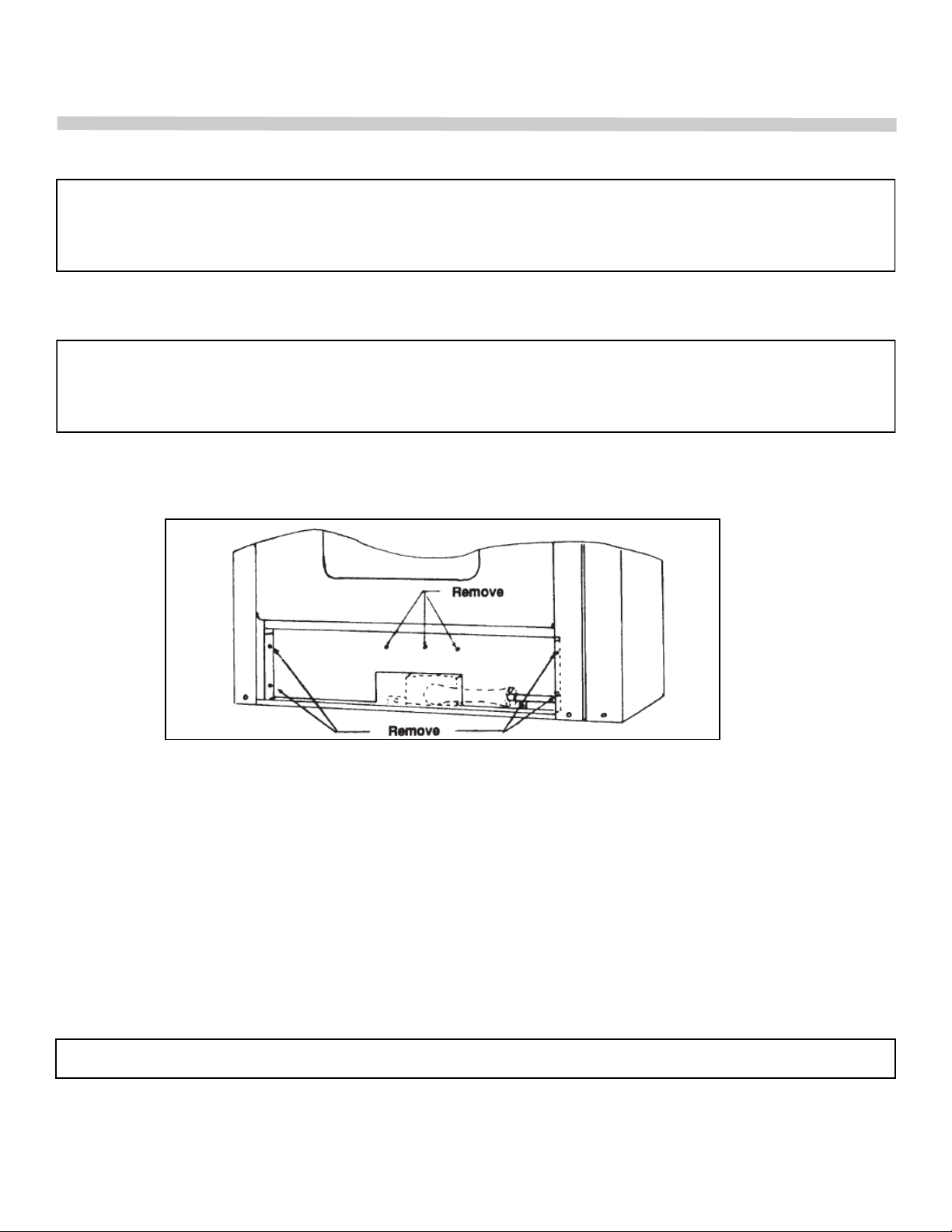
REMOVAL OF BURNER BOX FRONT AND BURNER BAFFLE
1. Remove Burner Box Panel.
2. Remove oven burner, pilot burner and thermocouple.
3. Remove 7 screws as shown, tilt top of burner box front forward and
pull out to clear orifice and manifold.
4. Pull burner baffle (P/N 04344-3 or 34904-6). To replace, reverse
a above procedure.
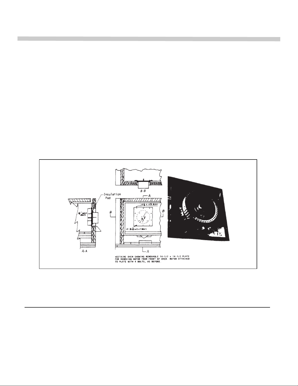
REMOVAL OF MOTOR AND FAN ASSEMBLY
DISCONNECT ELECTRICAL POWER TO OVEN(S) BEFORE SERVICING.
1. Remove six (6) screws at bottom, top and middle of fan baffle and pull forward.
2. Remove the ten (10) 1/4" bolts holding Motor Mount Plate in back of oven.
31
Page 32
SERVICE
3. Pull plate forward 1-1/4" to 1-1/2" so that motor flange clears the 10" cut out in back of
oven. Then let motor drop and rest on frame. (The first time this is done, the 1/8" thick
rectangular insulation pad between motor and oven back will have to be forced to fit round
10" hole) Pull motor through hole and rest on oven bottom. Reach behind plate and remove
top of electrical box mounted on motor. Mark or identify wires for reconnection. Disconnect
wire and remove flex from motor. Motor, panel and fan may then be removed from oven.
4. Remove two Allen screws from fan hub and pull off fan using wheel puller. A flange on
hub is provided so a wheel puller can be used.
5. Remove four hold-down nuts at motor mounting and remove motor. IMPORTANT: When
reinstalling motor, check alignment so that fan will not come into contact with plate or fan
baffle. Check wiring for proper voltage connection.
MOTORS – One of the following is used on each oven:
Electrical characteristics
PART NO. MFR HP SPEED VOLTAGE HZ PH___
01402-8 Baldor 3/4 1 115 / 230 60 1
02167-9 Howell 3/4 1 115 / 230 60 1
01397-8 Howell 3/4 2 115 60 1
06371-1 Howell 3/4 2 208 / 230 60 1
01403-6 Baldor 3/4 1 115 / 230 50 1
01404-4 Baldor 3/4 1 230 / 440 60 3
32
Page 33
SERVICE
SERVICE
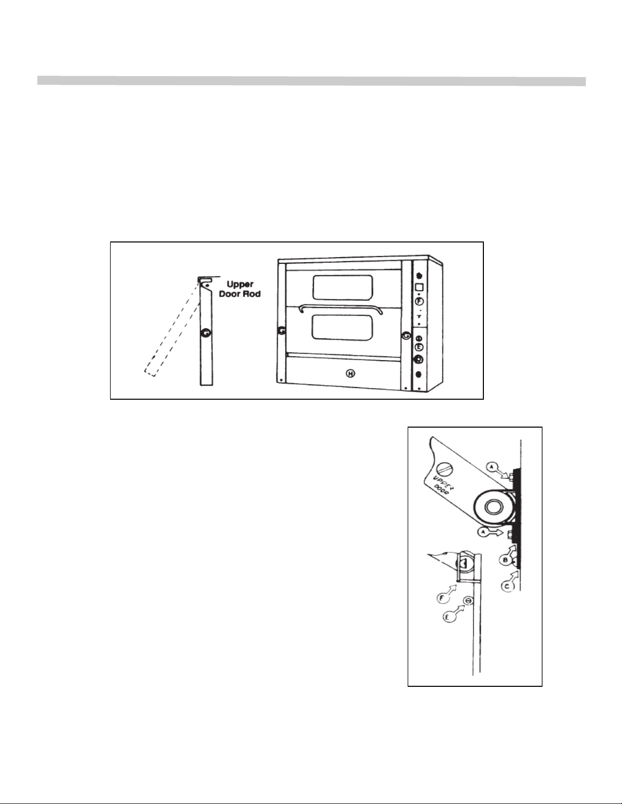
MODELS WITH SUFFIX ―Z‖
Removal of Gear Panels
1. Remove burner compartment panel.
2. Remove screw from lower edge of gear panel. Pull bottom edge of
panel forward so that top of panel clears upper door rod.
Synchronize Oven Door
1. Remove left & right gear panels.
2. Loosen Bolt ―A‖ (steps 2-5 should
apply to both upper bearings). 0))
3. Loosen Bolt holding Bearing ―E‖ so that Gear
Rack ―F‖ slacks off enough to allow corrugations
to slide up or down on ―C‖. NOTE: If upper door
extends out, raise door. If lower door extends out,
lower door.
4. Tighten Bolt ―A‖.
5. Tighten Bolt holding Bearing ―E‖.
6. Check Door Seal, adjust if needed.
33
Page 34

SERVICE
Adjusting Door Seal
It is important that the door seal be maintained across
entire door but not too tight.
1. Loosen Bolts I’D‖
2. Doors will slide up or down.
3. Tighten up Bolts ―D‖.
NOTE: If after doors are synchronized there is not enough
adjustment in bolt holes ―D‖, it will be necessary to loosen
Bearing ―E‖, move Gear Rack ―F‖ up or down one tooth as
needed. Door will have to be synchronized again.
OPERATION DIFFICULTIES AND PROBABLE CAUSES
Fan Shuts Off, Light in Oven On
1. Door open.
2. Door switch needs adjusting.
3. Motor overheating from lack of air circulation. Comes on when motor is cool.
4. Loose connection.
5. Fan or Door switch defective.
Fan Will Not Shut Off When Door Is Open
1. Door switch needs adjusting or defective.
2. Fan switch is ―Cool‖ positive.
3. Fan switch is defective.
Fan and Light Off
1. Electrical power supply turned off.
2. Plug disconnected.
Pilot Burner Goes Out - Except Models with Suffix ―EI‖
1. Main gas shut off valve turned off.
2. Minimum flame set too low and blows it out upon ignition of main burner.
3. Poor draft in flue snuffs out flame.
4. Too much draft - pulls flame away from thermocouple.
5. Pilot flame too low.
6. Thermocouple defective.
7. Thermocouple connection on safety pilot loose.
8. Pilot orifice dirty.
9. Safety pilot valve defective.
Burner Fails to Come on Though Pilot On
Gas Thermostat (Models with suffix ―G‖)
1. Main shut off valve turned off.
2. Orifice plugged.
3. Thermostat completely out of calibration.
34
Page 35

SERVICE
Electric Thermostat (Models with suffix ―E, EI‖)
1. Electric plug out.
2. Electric terminal loose.
3. Defective solenoid valve.
Oven Burner Will Not Shut Off or Oven Gets Too Hot
Gas Thermostat (Models with suffix ―G‖)
1. Oven thermostat out of calibration.
2. Minimum flame too high. (Do not lower under 1/4").
3. Broken capillary tube.
4. Dirt under thermostat valve seat.
Electric Thermostat (Models with suffix ―E, EI‖)
1. Oven thermostat out of calibration.
2. Broken capillary tube.
3. Wire shorting across thermostat terminals.
4. Dirt under seat of solenoid valve.
Oven Controls Overheating
1. Hole in top covered.
2. Range installed on control side conducting heat to control compartment,
(insulate side of oven).
3. Oven setting on curb without 111 toe base or legs.
4. Poor draft in flue. Heat coming out from of burner compartment and being
pulled up into control compartment instead of going out rear flue opening.
5. Door seal leaking.
Poor Heat Distribution - Hot Spots (See Baking Difficulties)
1. Too low gas input.
2. Thermostat out of calibration.
3. Fan not on.
4. Too much draft or too little draft in flue.
5. Poor seal across center of door.
6. Baffle too far from fan.
7. Foreign matter or obstruction in fan wheel or back of baffle.
8. Thermostat set too high.
Oven Takes a Long Time and/or Will Not Reach Temperature
1. Oven out of calibration.
2. Gas pressure too low.
Door Sticks or Not Closing Properly - Models with suffix ―Z‖
1. Gear rack interfering with spring assembly arm.
2. Broken spring.
3. Door out of synchronization.
4. Upper door hits top before stops on lower door makes a contact.
35
Page 36

SERVICE
Model with Suffix ―G‖
Model with Suffix ―F‖
Intermittent Fan Operation
36
Page 37
SERVICE
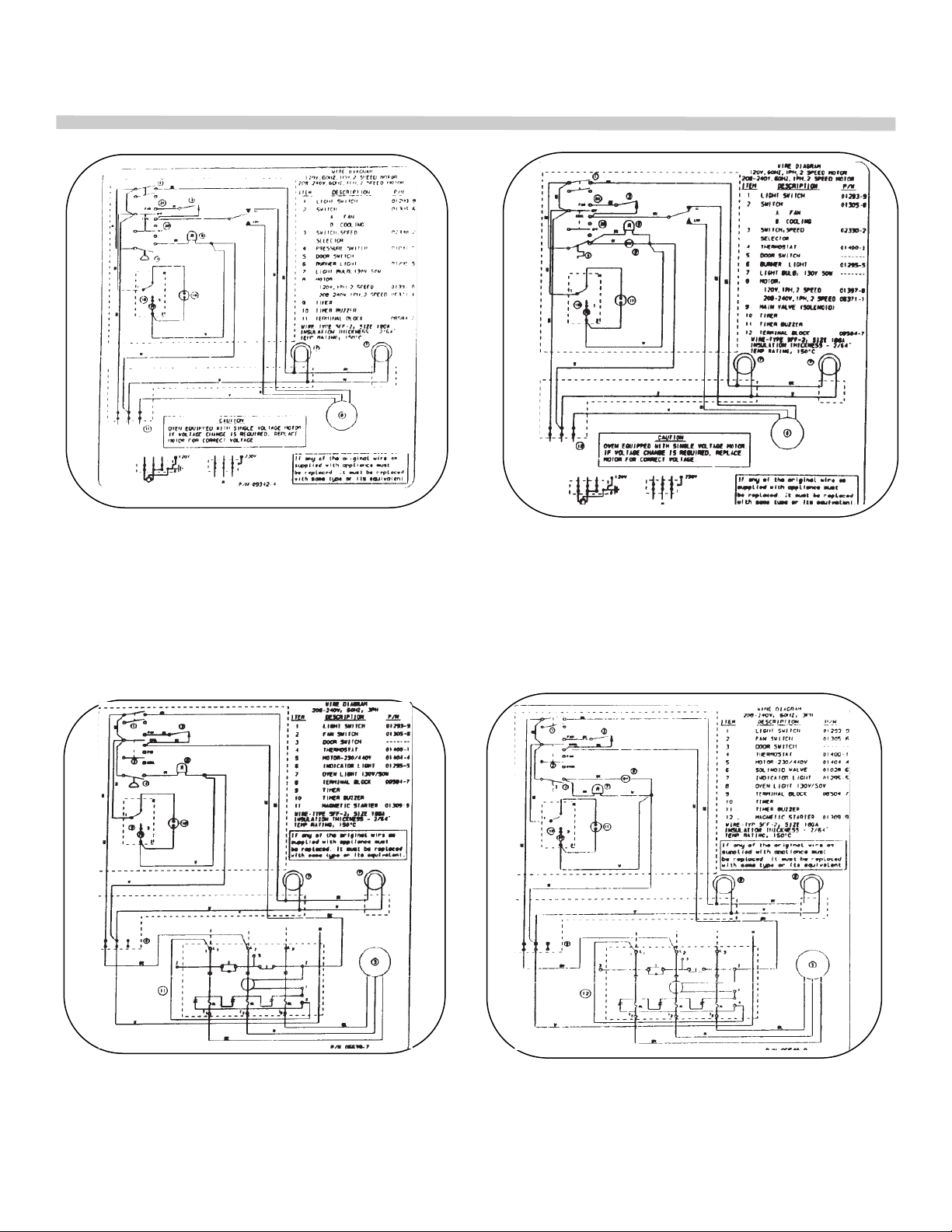
Model with Suffix ―G‖ — 2 speed Motor
Model with Suffix ―E‖ — 2 speed Motor
Model with Suffix ―G‖ — with Magnetic Starter
Model with Suffix ―E‖ — with Magnetic Starter
37
Page 38
SERVICE
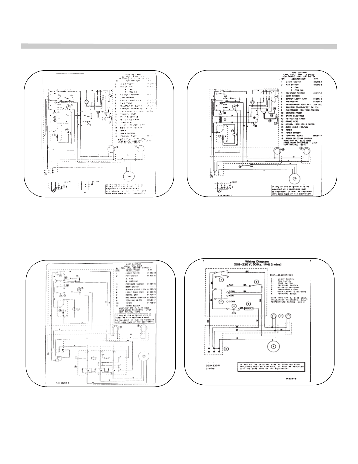
Model with Suffix ―EI‖ — 1 Speed Motor
120-240V, 60 Hz, 1PH
Model with Suffix ―EI‖ — 2 Speed Motor
120V, 60 Hz, 1PH
Model with Suffix ―E‖
480V, 60Hz, 3 PH w/ 120V Control Circuit
Model with Suffix ―E‖ — 50 Hz
38
Page 39

R85 Kits
RSI Single Unit Accessory Kit - Black 29241-9
includes: Gusset Legs; Single Unit Flue Deflector;
Attaching Hardware
RSI Single Unit Accessory Kit - SIS 29242-7
includes: Gusset Legs; Single Unit Flue Deflector;
Attaching Hardware
RD1 Double-stack Accessory and Flue Kit - Black 29243-5
includes: 6" Legs; Double-stack Flue Deflector; Flue Collector;
Flue Riser; Attaching Hardware
RD1 Double-stack Accessory and Flue Kit - S/S 29244-3
includes: 6" Legs; Double-stack Flue Deflector; Flue Collector;
Flue Riser; Attaching Hardware
RS2 Single Unit Drafthood Kit - Black 29245-1
includes: Single Unit Drafthood, which replaces single unit
flue deflector
RS2 Single Unit Drafthood Kit - S/S 29247-8
includes: Single Unit Drafthood, which replaces single unit
flue deflector
RD2 Double-stack Drafthood Kit - Black 29248-6
includes: Double-stack Unit Drafthood, which replaces
double-stack flue deflector, and flue box
RD2 Double-stack Drafthood Kit - S/S 29249-4
includes: Double-stack Unit Drafthood, which replaces
double-stack flue deflector, and flue box
39
Page 40
40 41
Page 41

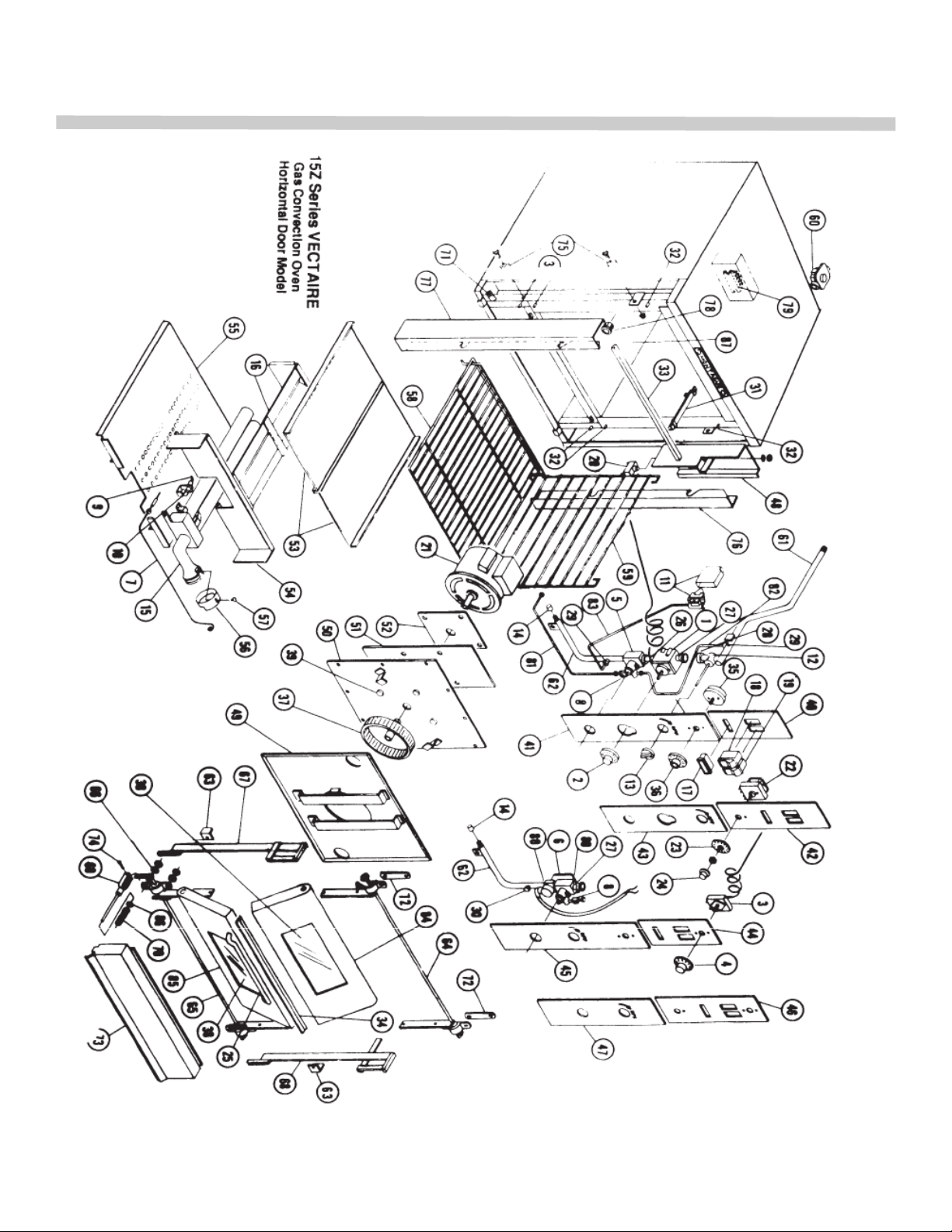
VECTAIRE Gas Convection Oven-Horizontal Door Model
1 ...... 3395-2 ....... Thermostat, Gas (FDO)
2 ...... 1024-3 ....... Dial, Thermostat-Gas
3 ...... 3499-1 ....... Thermostat, Electric (KX)
4 ...... 1979-8 ....... Dial, Thermostat-Electric
5 ...... 1025-1 ....... Safety Valve, Gas Thermostat
6 ...... 1028-6 ....... Safety Valve, Elec. Therm. (c#1 2)
6 ...... 1031-6 ....... Safety Valve, Elec.Therm. (G#1 -11)
7 ...... 1036-7 ....... Thermocouple
8 ...... 1051-0 ....... Pilot Valve
9 ...... 1033-2 ....... Pilot Burner-Natural Gas
9 ...... 1034-0 ....... Pilot Burner-Propane Gas
10 .... 2220-9 ....... Orifice, Pilot-Natural Gas
10 .... 2154-7 ....... Orifice, Pilot-Propane Gas
11 .... 22325-5 ..... Pressure Switch
12 .... 1038-3 ....... Main Valve
13 .... 2122-9 ....... Knob, Main Valve (Red)
14 .... 1044-8 ....... Orifice, Main Burner-Natural Gas
14 .... 6150-6 ....... Orifice, R85, Natural; 2 req'd. (after Jan.'05)
14 .... 1042-1 ....... Orifice, Main Burner-Propane Gas
14 .... 2277-2 ....... Orifice, R85, Propane; 2 req'd. (after Jan.'05)
15 .... 4349-4 ....... Main Burner-Natural Gas
15 .... 4355-9 ....... Main Burner-Propane Gas
15 .... 32431-0 ..... Burner Assy-R85 (after Jan.'05)
16 .... 4344-3 ....... Deflector (S/S)
16 .... 34904-6 ..... Deflector (S/S)-R85 (after Jan.'05)
17 .... 1295-5 ....... Light, Indicating ―Burner’ (110V)
18 .... 1293-9 ....... Switch, Light
19 .... 1305-6 ....... Switch, Fan-Off-Cool
20 .... 1300-5 ....... Switch, Door
21 .... 1402-8 ....... Motor, 115/208-240V 1 PH 60Hz Baidor
21 .... 2167-9 ....... Motor, 11 5/208-240V 1 PH 60Hz Howell
21 .... 1404-4 ....... Motor, 230/440V 3PH 60Hz Baldor
22 .... 1406-0 ....... Timer, Electric-1 1 OV
22 .... 1407-9 ....... Timer, Electric-220V
23 .... 2044-3 ....... Dial, Electric Timer
24 .... 2041-9 ....... Knob, Electric Timer
25 .... 3173-9 ....... Handle, Oven Door
26 .... 1150-9 ....... Nipple, 3/8"x 2"
27 .... 1149-5 ....... Nipple, 3/8"x 1-1/2"
28 .... 1183-5 ....... Union, 3/8"
29 .... 1277-7 ....... Fitting-1 /8" NPT x 1/4" CC
30 .... 1279-3 ....... Plug, 1/8"NPT
31 .... 6156-5 ....... Holder, Capillary Tube
32 .... 1944-5 ....... ―D‖ Bolt, 5/16" x 1 ―
33 .... 4376-1 ....... Door Seal, Upper-Metal
34 .... 4381-8 ....... Door Seal, Center-Metal
35 .... 2125-3 ....... Timer, Mechanical
36 .... 2043-5 ....... Dial, Mechanical Timer
37 .... 2123-7 ....... Fan Wheel with Set Screw
38 .... 2124-5 ....... Window
39 .... 1945-3 ....... Bolt, Motor Mounting
40 .... 11752-8 ..... Panel, Upper Gas Therm. (Mech. Timer)
41 .... 11750-1 ..... Panel, Lower 1.
42 .... 4562-4 ....... Panel, Upper (Elec. Timer)
43 ....................... Panel. Lower 1
44 .... 4309-5 ....... Panel, Upper El. Therm. (Mech. Timer)
45 .... 4308-7 ....... Panel, Lower 11
46 .... 4564-0 ....... Panel, Upper (Elec. Timer)
47 .... 4563-2 ....... Panel, Lower
48 ....................... Panel, Switch Box Enclosure
49 .... 1522-9 ....... Rear Fan Baffle, Porcelain
50 .... 4375-3 ....... Motor Mounting Plate
51 .... 1757-4 ....... Insulation Pad, Motor
52 .... 4385-0 ....... Spacer Plate, Motor
53 .... 4583-7 ....... Top, Burner Box Plate (2 piece)
54 .... 7006-8 ....... Front, Burner Box
55 .... 7779-8 ....... Perf. Bottom, Burner Box
55 .... 34895-3.... Perf. Bottom, Burner Box-R85 (after 1/05)
56 .... 4494-6 ....... Air Shutter
57 .... 1860-0 ....... Bolt, Wing 1/4-20
58 .... 1590-3 ....... Rack, Oven Standard
59 .... 1594-6 ....... Rack Guide, Right
........ 1593-8 ....... Rack Guide, Left (Not Shown)
60 .... 1039-1 ....... Regulator-Natural Gas (3/4")
60 .... 1040-5 ....... Regulator-Propane Gas (3/4")
61 .... 6851-9 ....... Manifold, Main (3/4")
62 .... 1099-5 ....... Manifold. Lower (1 /2")
62 .... 34934-8 ..... Manifold Assy.-R85 (after Jan.'05)
63 .... 4433-4 ....... Guide, Gear Rack
64 .... 3578-5 ....... Trunnion, Upper Door
65 .... 3575-0 ....... Trunnion, Lower Door
66 .... 1904-6 ....... Spacer, Door (1/2‖)
67 .... *3596-3 ...... Gear Rack, Left
68 .... **3611-0 .... Gear Rack, Right
69 .... 3408-8 ....... Yoke with Guide Pin
70 .... 2024-9 ....... Spring, Door Assembly
71 .... 3411-8 ....... Replacemant Yoke Pin Guide
72 .... 3597-1 ....... Spacer, Upper Trunnion
73 .... 4411-3 ....... Firebox Panel (S/S)
74 .... 3412-6 ....... Pin, Yoke
75 .... 3413-4 ....... Bearing with Bolt and Nut
76 .... 6015-1 ....... Panel, Right Gear Cover
77 .... 4581-0 ....... Panel, left Gear Cover
78 .... 1408-7 ....... Light Socket
79 .... 8584-7 ....... Terminal Block
80 .... 1119-3 ....... Bushing, 3/8"x 1/2" NPT
81 .... 1229-7 ....... Tube, Safety Valve to Pilot
81 .... 25013-9 ..... Tube, Manifold to Valve-R85(1/05)
82 .... 1225-4 ....... Tube, Manifold to Safety Valve
84 .... 4348-6 ....... Upper Door with Window
85 .... 3606-4 ....... Lower Door with Window
86 .... 3488-6 ....... Keeper, Door Bearing
87 .... 1524-5 ....... Oven Bottom, Porcelain
88 .... 6949-3 ....... Pilot Shield
*Left gear racks for oven prior to 1963-P/N 3610-2
**Right gear racks for ovens prior to 1974—consult with factory for correct number and
Page 42
42 43
Page 43

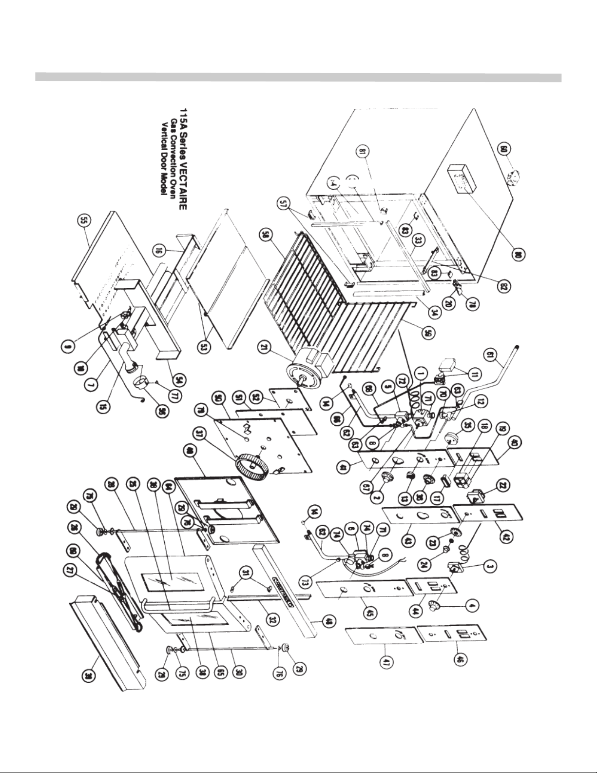
VECTAIRE Gas Convection Oven-Vertical Door Model
1 ...... 3395-2 ....... Thermostat, Gas (FDO)
2 ...... 1024-3 ....... Dial, Thermostat—Gas
3 ...... 3499-1 ....... Thermostat, Electric (KX)
4 ...... 1979-8 ....... Dial, Thermostat-Electric
5 ...... 1025-1 ....... Safety Valve, Gas Thermostat
6 ...... 1028-6 ....... Safety Valve, Elec Therm. (c#12)
6 ...... 1031-6 ....... Safety Valve, Elec.Therm. (c#1 -11)
7 ...... 1036-7 ....... Thermocouple
8 ...... 1051-0 ....... Pilot Valve
9 ...... 1033-2 ....... Pilot Burner—Natural Gas
9 ...... 1034-0 ....... Pilot Burner—Propane Gas
10 .... 2220-9 ....... Orifice, Pilot— Natural Gas
10 .... 2154-7 ....... Orifice, Pilot-I’mr-ine Gas
11 .... 1037-5 ....... Pressure Switch
12 .... 1038-3 ....... Main Valve
13 .... 1122-9 ....... Knob, Main Valve (Red)
14 .... 1044-8 ....... Orifice, Main Burner-Natural
14 .... 6150-6 ....... Orifice, R85, Natural; 2 req'd. (after Jan.'05)
14 .... 1042-1 ....... Orifice, Main Burner-Propane
14 .... 2277-2 ....... Orifice, R85, Propane; 2 req'd. (after Jan.'05)
15 .... 4349-4 ....... Main Burner-Natural Gas
15 .... 4355-9 ....... Main Burner-Propane Gas
15 .... 32431-0 ..... Burner Assy-R85 (after Jan.'05)
16 .... 4344-3 ....... Deflector (S/S)
16 .... 34904-6 ..... Deflector (S/S)-R85 (after Jan.'05)
17 .... 1295-5 ....... Light, Indicating ―Burner‖(110V)
18 .... 1293-9 ....... Switch, Light
19 .... 1305-6 ....... Switch, Fan-Off -Cool
20 .... 1300-5 ....... Switch, Door
21 .... 1402-8 ....... Motor, 115/208-240V 1 PH 60Hz Baldor
21 .... 2167-9 ....... Motor, 115/208-240V 1 PH 60Hz Howell
21 .... 1404-4 ....... Motor, 230/440V 3PH 60Hz Baldor
22 .... 1406-0 ....... Timer, Electric-110V
22 .... 1407-9 ....... Timer, Electric-220V
22 .... 4385-0 ....... Spacer Plate, Motor
23 .... 2044-3 ....... Dial, Electric Timer
24 .... 2041-9 ....... Knob, Electric Timer
25 .... 3173-9 ....... Handle, Oven Door
26 .... 2016-8 ....... Chain, Oven Door
27 .... 3172-0 ....... Turnbuckle-with Rods
28 .... 3239-5 ....... Trunnion, Left
29 .... 2014-1 ....... Bearing, Oven Door
30 .... 3585-8 ....... Trunnion, Right
31 .... 3414-2 ....... Spring Clip, Door (2 each)
32 .... 4379-6 ....... Door Seal, Center-Metal
33 .... 4376-1 ....... Door Seal, Upper-Metal
34 .... 4378-8 ....... Door Seal, Side-Metal
35 .... 2125-3 ....... Timer, Mechanical
36 .... 2043-5 ....... Dial, Mechanical -Timer
37 .... 2123-7 ....... Fan Wheel with Set Screw
38 .... 2124-5 ....... Window
39 .... 3593-9 ....... Firebox Panel, Clip Style (S/S)
39 .... 7068-8 ....... Firebox Panel, Magnet Style (S/S)
40 .... 6967-1 ....... Panel, Upper Gas Therm. (Mech. Timer)
41 .... 4487-3 .......Panel, Lower
42 ....................... Panel, Upper (Elec. Timer)
43 ....................... Panel. Lower 11
44 .... 6958-2 .......Panel, Upper El. Therm. (Mech. Timer)
45 .... 4459-8 .......Panel, Lower 1.
46 ....................... Panel, Upper (Elec. Timer)
47 ........... ......... Panel, Lower 1.
48 .... 4575-6 .......Capping Panel, Upper Front (S/S)
49 .... 1522-9 .......Rear Fan Battle, Porcelain
........ 4375-3 ....... Motor Mounting Plate
51 .... 1757-4 .......Insulation Pad, Motor 8
53 .... 4583-7 .......Top, Burner Box Plate (2 piece)
54 .... 7006-8 .......Front, Burner Box
55 .... 7779-8 .......Perf. Bottom, Burner Box
55 .... 34895-3 .....Perf. Bottom, Burner Box-R85 (after 1/05)
56 .... 4494-6 ....... Air Shutter
57 .... 6949-3 ....... Pilot Shield
57 .... 2040-0 ....... Magnet, Firebox Panel
58 .... 1590-3 ....... Rack, Oven Standard
59 .... 1594-6 ....... Rack Guide, Right
........ 1593-8 ....... Rack Guide, Left (Not Shown)
60 .... 1039-1 ....... Regulator-Natural Gas (3/4")
60 .... 1040-5 ....... Regulator-Propane Gas (3/4")
61 .... 6851-9 ....... Manifold, Main (3/4")
62 .... 1099-5 ....... Manifold. Lower (1/2")
62 .... 34934-8 ..... Manifold Assy.-R85 (after Jan.'05)
63 .... 1277-7 ....... Fitting-1/8" NPT x 1/4" CC
64 .... 3607-2 ....... Door, Handle Side
65 .... 3608-0 ....... Door, Right Side
66 .... 1229-7 ....... Tube, Safety Valve to Pilot
66 .... 25013-9 ..... Tube, Manifold to Valve-R85(1/05)
67 .... 1225-4 ....... Tube, Manifold to Safety Valve
69 .... 4399-0 ....... Guard, Chain Assembly
70 .... 1183-5 ....... Union, 3/8"
71 .... 11 49-5 ...... Nipple, 3/8" x 1- 1/2"
72 .... 1150-9 ....... Nipple, 3/8" x 2"
73 .... 1279-3 ....... Plug, 1/8" NPT
74 .... 1119-3 ....... Bushing, 3/8" x 1/2" NPT
75 .... 1904-6 ....... Spacer, Door (1/2')
76 .... 1961-5 ....... Keeper, Door Trunnion
77 .... 1860-0 ....... Bolt, Wing 1/4-20
78 .... 11869-9 ..... Bracket, Door Switch
79 .... 1945-3 ....... Bolt Motor Mounting
80 .... 8584-7 ....... Terminal Block
81 .... 1408-7 ....... Light Socket
82 .... 6156-5 ....... Holder, Capillary Tube
83 .... 3488-6 ....... Keeper, Door Bearing
84 .... 1524-5 ....... Oven Bottom, Porcelain
Page 44
WARNING
If not installed, operated and maintained
in accordance with the manufacturer's
instructions, this product could expose you
to substances in fuel or in fuel combustion
which can cause death or serious illness
and which are known to the State of
California to cause cancer, birth defects or
other reproductive harm.
The State of California enacted the California Safe Drinking Water and Toxic Enforcement Act of 1986, (Prop. 65), which
"prohibits any person in the course of doing business from knowingly and intentionally exposing any individual to a chemical
known to the State of California to cause cancer or reproductive toxicity without first giving clear and reasonable warning t o
such individuals." The Governor's Scientific Advisory Panel added carbon monoxide to the list of hazardous chemicals
known to cause reproductive harm.
In order to establish full compliance with Proposition 65, we attached a yellow warning label to each gas fired unit manufactured by the Montague Company.
Carbon monoxide would not be present in concentrations that would pose a "significant risk" to the consumer when the
equipment is installed, operated and maintained as follows:
1. Installed in accordance with all local codes, or in the absence of local codes, with the current
National Fuel Gas Code Z223.1.
2. Installed under a properly designed and operating exhaust hood.
3. Connected to the type of gas for which the unit is equipped.
4. Proper appliance pressure regulator installed on the gas supply line and adjusted for the manifold
pressure marked on the rating plate.
5. Adequate air supply to the unit.
6. The equipment is operated in the manner intended using the proper utensil for that type of appliance.
7. Keep the equipment clean and have it checked periodically.
8. Burner air adjustments, mechanical maintenance and repairs should be performed by qualified
service personnel.
If the equipment is not installed, operated and maintained in accordance with the above, concentrations of carbon monoxide
in excess of the established limits could present in the kitchen environment.
ALL PERSONNEL IN THE WORKPLACE WHO MAY BE SUBJECT TO ANY EXPOSURE OF CARBON
MONOXIDE MUST BE WARNED OF SUCH POSSIBLE EXPOSURE. THIS WARNING SHOULD BE
CONVEYED IN A MANNER SO THAT IT IS CLEARLY UNDERSTOOD BY THE EMPLOYEE, AND
THE EMPLOYEE SHOULD BE ASKED IF IN FACT HE OR SHE UNDERSTANDS THE CORRECT
METHOD OF OPERATION OF THE EQUIPMENT AND THAT A RISK OF EXPOSURE EXISTS IF THE
EQUIPMENT IS OPERATED IMPROPERLY.
The MONTAGUE COMPANY
1830 Stearman Avenue, P.O. Box 4954 Hayward, CA 94540-4954
44
Page 45
IMPORTANT
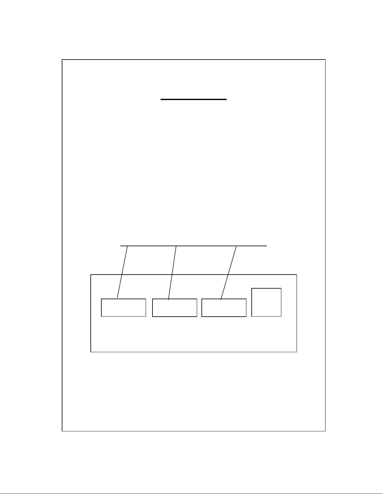
When ordering part, to eliminate mistakes and facilitate delivery, always give
the following information:
Serial No. _____________________________________________
Model No. _____________________________________________
Change No. ____________________________________________
Name & No. of Part
Model No. Change No. Serial No.
The Montague Company
1830 Stearman Avenue
P.O. Box 4954
Hayward, CA 94540-4954 (REV. B) P/N 4520-9 1/05
45
 Loading...