

Page 1
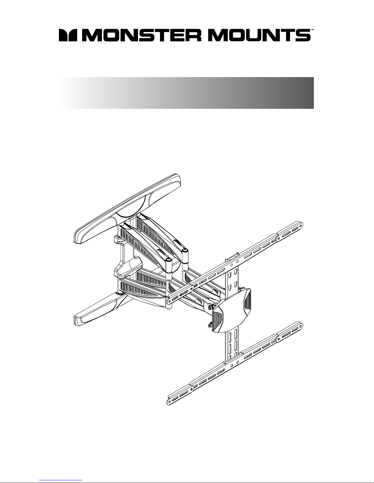
SLIM FULL MOTION MOUNT
MA641
Display Size: 30” -70”
Maximum load: 100 lbs / 45 kg
VESA Patterns: 100 x 100 to 600 x 400
USER MAN U A L
ATTENTION: BEFORE INSTALLING, READ ALL WARNINGS AND CAUTIONS ON REVERSE SIDE.
FOR MORE INFORMATION, GO TO:
www.monstermounts.com
Page 2
IT IS HIGHLY RECOMMENDED THAT THIS PRODUCT BE INSTALLED BY A PROFESSIONAL.
PLEASE REVIEW THIS INSTRUCTION MANUAL COMPLETELY BEFORE STARTING THE
INSTALLATION PROCESS.
WARNING: A WARNING alerts you to the possibility of serious injury or death if you do not
follow the instructions.
CAUTION: A CAUTION alerts you to the possibility of damage or destruction of equipment if
you do not follow the corresponding instruction.
WARNING: Improper installation can result in serious personal injury! Make sure that the
structural members can support a weight factor ve times the total weight of the
equipment. If not, reinforce the structure before starting the installation.
WARNING: Be aware also of the potential for personal injury or damage to the unit if it is not
adequately mounted.
WARNING: The installer is responsible for verifying that the wall or ceiling to which the
mount is anchored will safely support the combined load of all attached components or
other equipment.
WARNING: The weight of the display placed on the mount must not exceed the maximum
load capacity of the mounts.
WARNING: Watch for pinch points. Do not put your ngers between movable parts.
WARNING: Make sure the mount and brackets are correctly oriented.
CAUTION: Check the unit for shipping damage before you begin the installation.
CAUTION: Do not overtighten bolt.
Warnings & Cautions
2
Page 3
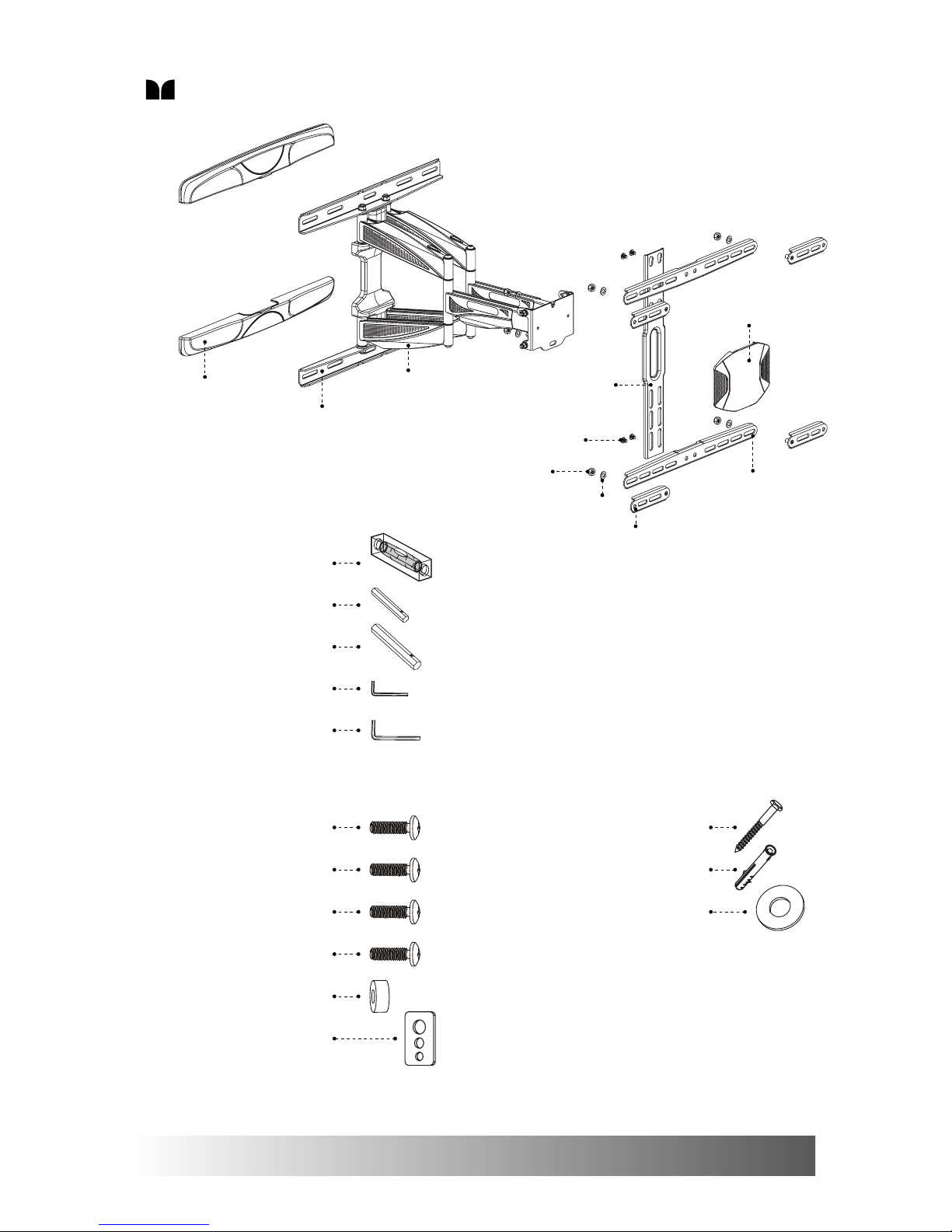
Package contents
3
1 Bubble level (x1)
2 M6 box wrench (x1)
3 M8 box wrench (x1)
4 #4 allen key (x1)
5 #5 allen key (x1)
A1 M4x25 mm bolt (x4)
A2 M5x25 mm bolt (x4)
A3 M6x25 mm bolt (x4)
A4 M8x25 mm bolt (x4)
A5 Spacer (optional) (x4)
A6 Square washer (x4)
B1 Lag bolt (x6)
B2 Concrete anchor (x6)
B3 Washer (x6)
Wall plate cover (x2)
Wall plate (x1)
Cable cover (x6)
VESA adaptor (x4)
M8 washer (x6)
Vertical bracket (x1)
M8 nut (x6)
M6 bolt (x4)
Horizontal bracket (x2)
Front cover (x1)
Page 4
4
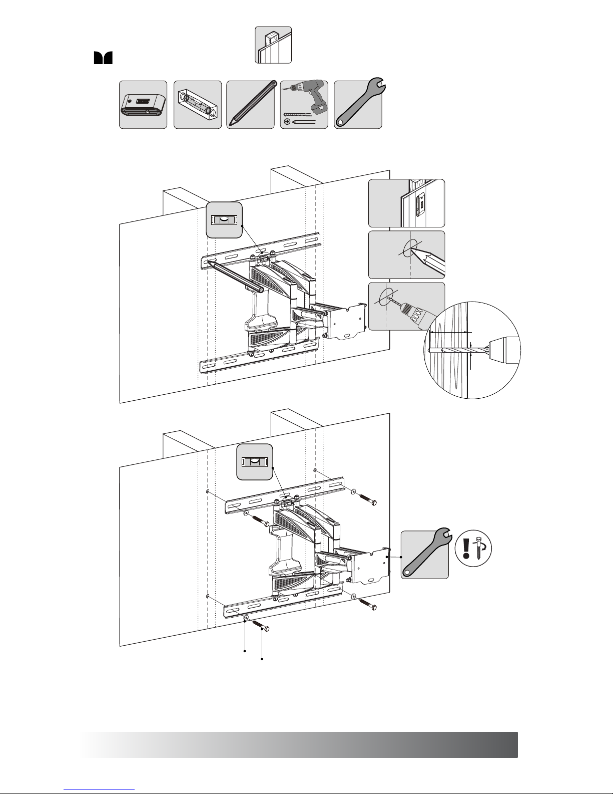
1a. Mount on Wood Wall
B1
B3
1
3
2
x4
60 mm
(2.4”)
Ø5 mm
(Ø3/16”)
Page 5
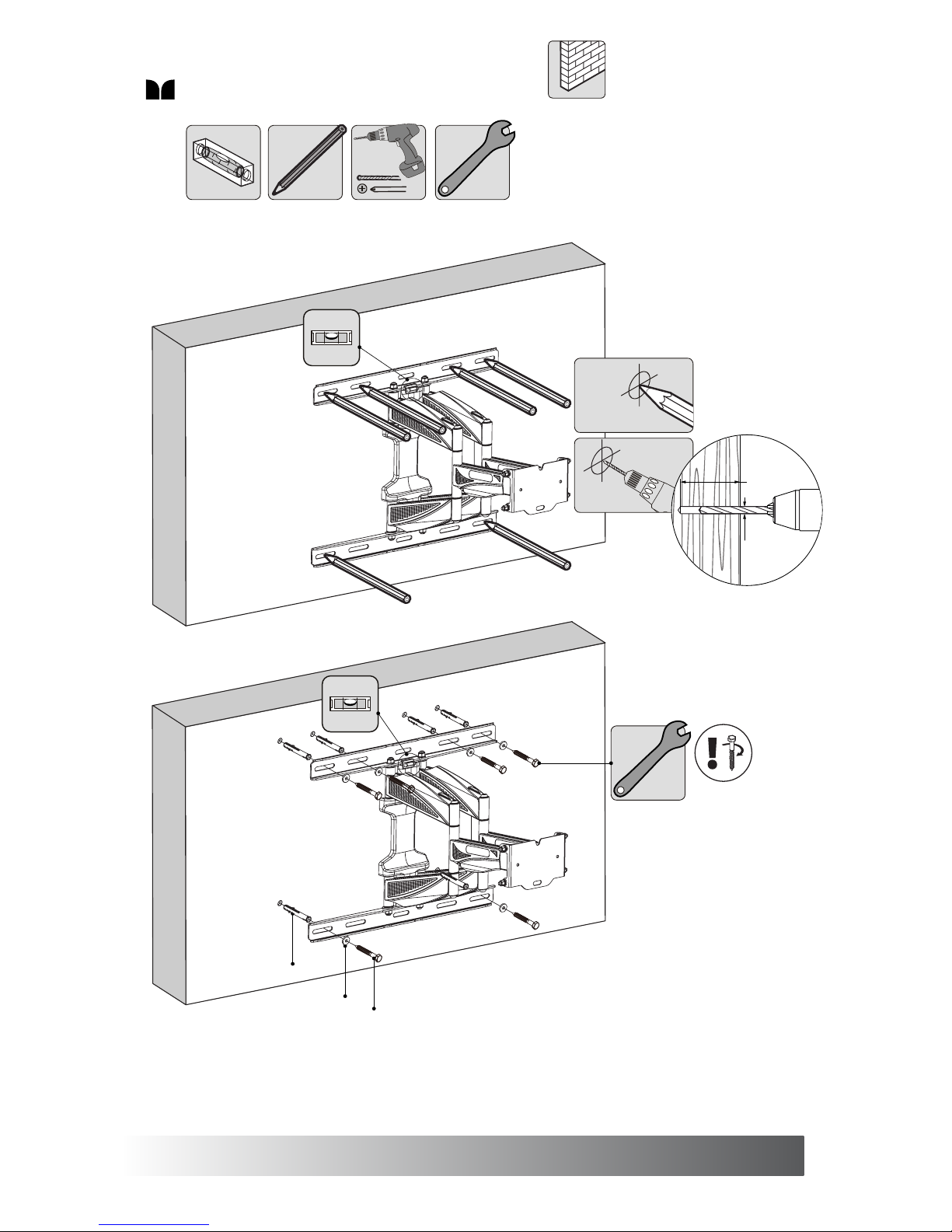
1b. Mount on Solid Brick or Concrete Block
5
1
x6
2
60 mm
(2.3”)
Ø10.5 mm
(Ø7/16”)
B1
B3
B2
Page 6
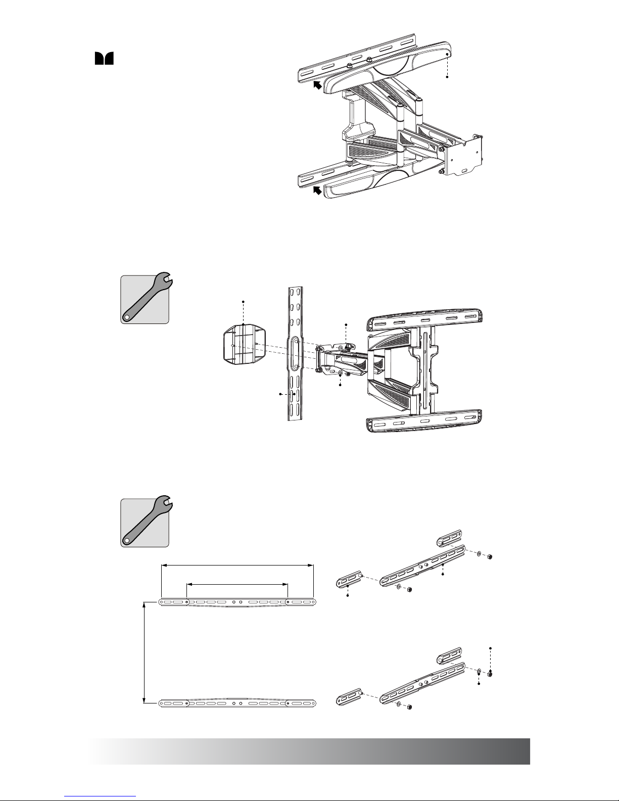
3. Install the Front Cover and Vertical Bracket
4. Install the VESA Adaptors (for TVs with horizontal VESA 600 only)
2. Install the Wall Plate Covers
6
Wall plate cover
Front cover
M8 nut
Vertical bracket
M8 washer
VESA 400 (mm)
VESA 400 (mm)
VESA 600 (mm)
Horizontal bracket
VESA adaptor
M8 nut
M8 washer
Page 7
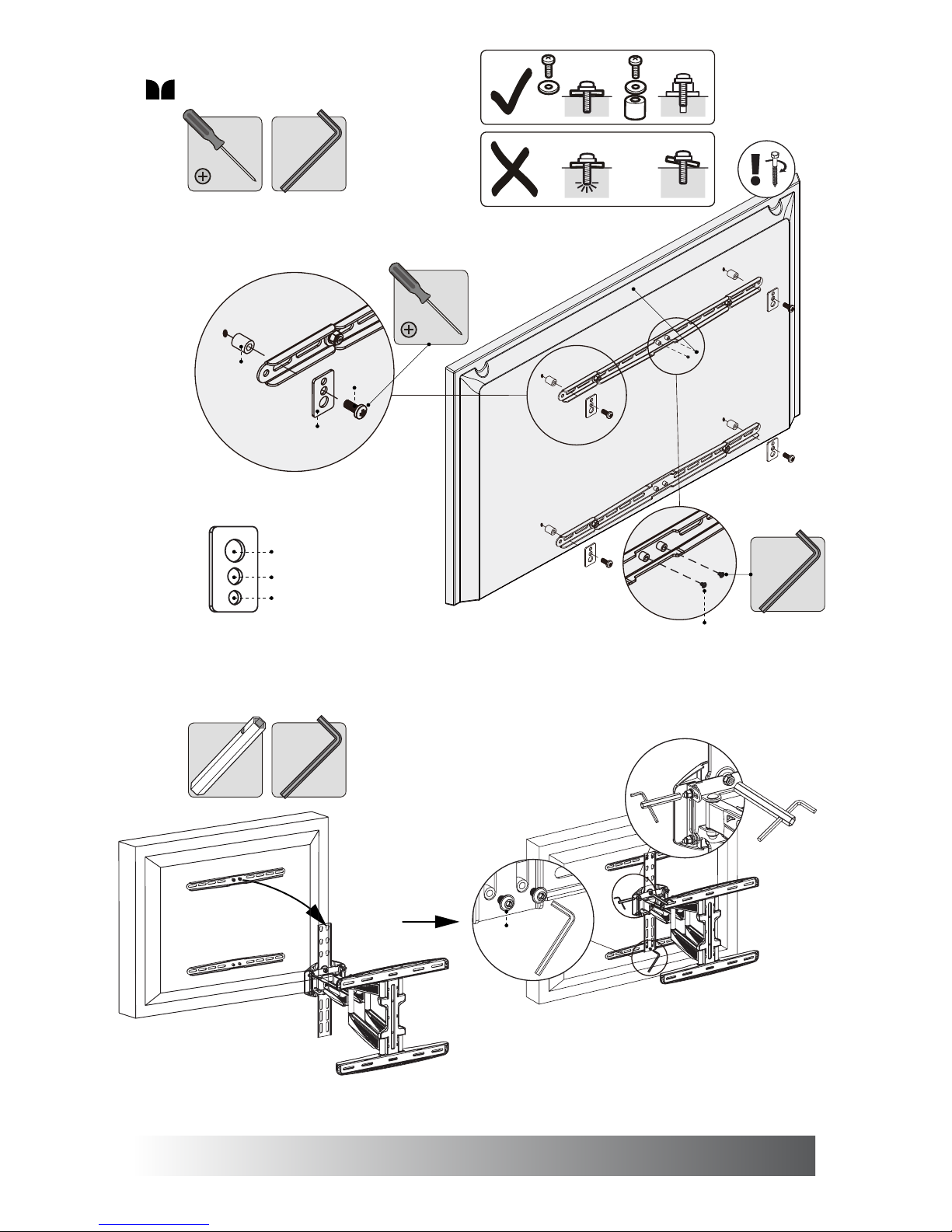
5. Install the Horizontal Brackets
6. Hang the TV from the Arm
7
M8 bolts
M5 and M6 bolts
M4 bolts
A6 Square Washer
A1-4
A5
A6
M6 bolt
tv tv
tv tv
M6 bolt
M8 box wrench
to adjust
horizontal level
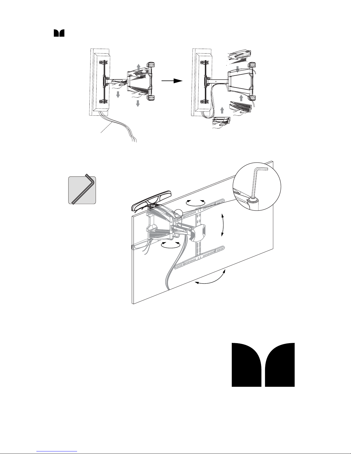
M6 box wrench
to adjust
tilt tension
Page 8
AUM120 v2.5
Monster Mounts
20218 Hamilton Avenue
Torrance, CA 90502
USA
FOR MORE INFORMATION, VISIT:
www.monstermounts.com
Cables
-2˚ to 12˚
±3˚
±90˚
Attach cable covers
after routing cables
Detach cable covers
7. Cabling the TV
8. Adjustments & Use
±45˚
 Loading...