

Page 1

http://hespareparts.com
COMPAGNIE RIBOULEAU
Réf. LD2003
PNEUMATIC PLANTER
Operator’s Manual
16-Row 30" Pull type Planter
WING FOLD
Includes Instructions For :
OPERATION, ADJUSTMENT and MAINTENANCE
Page 2

http://hespareparts.com
Introduction 1
Specifications 2
Safety 3
Operation 5
Lubrication 27
Maintenance 30
Parts 37
High output turbofan 38
Hydraulic drive 40
Planting unit – NG plus 2 41
Metering box – NG plus 44
Microsem 46
Fertilizer 48
PVC pipe and hose assembly 50
Frame assembly 51
Hydraulic wing fold 53
Hitch assembly 54
Row marker assembly 56
Marker support 58
Marker – hose – spindle – hub 59
Lift wheel assembly 60
Drive wheel assembly 61
Transmission assembly 64
Hex shaft coupler 66
Hydraulic assembly 67
Lift assist cylinder assembly 69
Wing fold cylinder assembly 70
Slave cylinder assembly 71
Master cylinder assembly 72
Marker cylinder assembly 73
Page 3

Introduction
http://hespareparts.com
2 precautions
for successful
planting :
1- Choose a reasonable working speed
adapted to the field conditions and desired
accuracy.
2- Check proper working of the seed
metering, seed placement, spacing and
density when starting up and from time to
time during planting.
… and don’t forget : accurate planting is
the key to a good stand !
1
Page 4

Specifications
http://hespareparts.com
TYPE - Pull Type - Center-Flex Hydraulic Front Fold, 16 Row
PLANTING UNIT TYPES - NG plus MONOSEM
- Pneumatic metering box
- Double disc opener
- Gauge wheels
- “V” closing wheels
STANDARD ROW SPACING - 16 Row Narrow - 30" Rows
TRANSPORT TIRES - Eight 7.50" x 20" , 6 ply Transport/Ground drive tires
- Adjustable height wheels for ridge planting
TYPE LIFT - Master/Slave hydraulics
16 Row master/slave rephasing with assist cylinders (8
cylinders)
ROW MARKERS - Heavy-duty conventional : Low profile three-fold
HYDRAULICS - Hydraulics for 16 Row dual SCV for independent operation
of lift and markers.
- Hydraulic sequence valve with flow controls for markers.
- Hydraulics for front fold 16 Row.
Dimensions/Weights
PLANTER SIZE 16 Row 30"
Transport Width 23' 2" (7100 mm)
Single Frame Length 24' 6" (7500 mm)
Single Frame Weight* 10489 lbs. (4760 Kg)
* The base machine weight includes planter frame, row markers, drive components, tires and
wheels, hydraulic cylinders and NG plus MONOSEM row unit with seed hopper and lid.
2
Page 5

Safety
http://hespareparts.com
!
! !
Following Operation :
• Following operation, or when unhitching,
stop the tractor or towing vehicle, set the
brakes, disengage the PTO and all
power drives, shut off the engine and
remove the ignition keys.
• Store the planter in an area away from
human activity.
• Do not permit children to play on or
around the stored planter.
• The planter should be stored in a dry and
dust-free location with the hydraulic
cylinders closed.
• Engage all safety devices for storage.
• Wheel chocks may be needed to prevent
the parked planter from rolling.
Performing Maintenance :
• Good maintenance is your responsibility.
• Make repairs in an area with plenty of
ventilation. Never operate the engine of
the towing vehicle in a closed building.
The exhaust fumes may cause
asphyxiation.
• Before working on the planter, stop the
towing vehicle, set the brakes, disengage
the PTO and all power drives, shut off
the engine and remove the ignition keys.
• Be certain all moving parts have come to
a complete stop before attempting to
perform maintenance.
• Always use the proper tools or
equipment for the job at hand.
• Never use your hands to locate a
hydraulic leak. Use a small piece of
cardboard or wood. Hydraulic fluid
escaping under pressure can penetrate
the skin. If injured by escaping
hydraulic fluid, see a doctor at once.
Gangrene can result. Without
immediate medical treatment, serious
infection and reactions can occur.
• Replace all shields and guards after
servicing and before moving.
• After servicing, be sure all tools, parts
and service equipment are removed.
• If the planter has been altered in any way
from the original design, the
manufacturer does not accept any
liability for injury or warranty.
Tire Safety :
• Inflating or servicing tires can be
dangerous. Whenever possible, trained
personnel should be called to service
and / or mount tires.
• Do not attempt to mount a tire unless you
have the proper equipment and
experience to do the job.
• Failure to follow proper procedures when
mounting a tire on a wheel or rim can
produce an explosion which way result in
serious injury or death.
3
Page 6

Safety
http://hespareparts.com
! !
Before Operation :
• Carefully study and understand this
manual.
• Do not wear loose-fitting clothing which
may catch in moving parts.
• It is recommended that suitable
protective hearing and (eye protection)
sight protectors be worn.
• The operator may come in contact with
certain materials witch may require
specific safety equipment, relative to the
handling of such materials (examples :
extremely dusty, molds, fungus, bulk
fertilizers, insecticides, etc.)
• Assure that the planter tires are inflated
evenly.
• Give the planter a visual inspection for
any loose bolts, worn parts or cracked
welds, and make necessary repairs.
• Be sure that there are no tools lying on
or in the planter.
• Don’t hurry the learning process or take
the unit for granted. Ease into it and
become familiar with your new planter.
• Practice operation of your planter and its
attachments. Completely familiarize
yourself and other operators with its
operations before using.
• Do not allow anyone to stand between
the tongue or hitch and the towing
vehicle when backing up the planter.
During Operation :
• Beware of bystanders, particularly
children ! Always look around to make
sure that it is safe to start the engine of
the towing vehicle.
• No passengers allowed anywhere on, or
in the planter during operation.
• Keep hands and clothing clear of moving
parts.
• Do not clean, lubricate or adjust your
equipment while it is moving.
• When halting operation, even
periodically, set the tractor or towing
vehicle brakes, disengage the PTO, shut
of the engine and remove the ignition
key.
• Be especially observant of the operating
area and terrain – watch for holes, rocks
or other hidden hazards. Always inspect
the area prior the operation.
Do not operate near the edge of dropoffs or banks.
Do not operate on steep slopes as
overturn may result.
Be extra careful when working on
inclines.
• As a precaution, always recheck the
hardware on equipment following every
100 hours of operation. Correct all
problems.
4
Page 7
Operation
http://hespareparts.com
PLANTER PREPARATION
For the initial preparation of the planter,
lubricate the planter and row units as
outlined in the lubrication section of this
manual. Make sure all tires are properly
inflated, that all drive chains have the proper
tension, alignment and lubrication.
TRACTOR PREPARATION
Consult your dealer for information on the
minimum tractor horse power requirements
and tractor capability. Tractor requirements
will vary with planter options, tillage and
terrain.
One dual remote hydraulic outlet (SCV) is
required on models equipped with the
standard single valve hydraulic system. Two
dual remote hydraulic outlets (SCV) are
required on models equipped with the
optional dual valve hydraulic system.
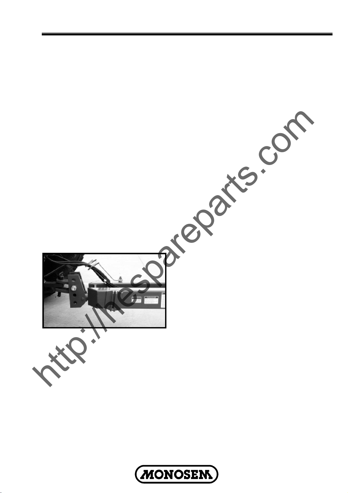
PLANTER ATTACHMENT TO TRACTOR
Use the following six steps to attach your
planter to the tractor.
1. Adjust the tractor drawbar so it is 13
to 17 inches above the ground. Adjust the
drawbar so that the hitch pin holes is directly
below the center line of the PTO shaft. Make
sure the drawbar is in a stationary position.
2. Back the tractor to the planter and
connect them with a hitch pin. Make sure the
hitch pin is secured with a locking pin or
cotter pin.
3. Connect the PTO drive shaft to the
tractor. In addition to a standard 540 rpm
PTO, a 1000 rpm shaft is available.
CAUTION – Make sure that you
connect the proper end of the PTO to the
tractor. An arrow on the PTO indicates
the end of the constant velocity (double
clutch) that is attached to the tractor.
The following sticker is placed on your PTO
shaft for your safety...
DANGER – Rotating drive line
contact can cause death – keep away. Do
not operate without all driveline, tractor
and equipment shields in place ; without
drivelines securely attached at both ends,
and without driveline shields that turn
freely on driveline.
4. Connect the hydraulic hoses to tractor
ports in a sequence which is both familiar
and comfortable to the operator.
DANGER – Before applying
pressure to the hydraulic system, make
sure all connections are tight and hoses
and fittings have not been damaged.
Hydraulic fluid escaping under pressure
can have sufficient force to penetrate
skin, causing injury or infection.
CAUTION – Always wipe hose ends
to remove any dirt before connecting
couplers to tractor parts.
5
Page 8
Operation
http://hespareparts.com
5. Raise the jack stand and remount
horizontally on the storage bracket.
6. Lower the planter to the planting position
and check that the planter is level (front to
back and side to side). If the hitch height is
too high or too low, disconnect the planter
and adjust the hitch clevis in an up or down
position as necessary.
LEVELING THE PLANTER
For proper operation of the planter and row
units, it is important that the unit operate
level.
Unless the tractor drawbar is adjustable for
height, the fore and aft level adjustment must
be maintained by the position of the hitch
clevis. Holes in the hitch bracket allow the
clevis to be raised or lowered. When
installing clevis mounting bolt, tighten hex
nut to proper torque setting.
With the planter lowered to proper operating
depth, check to be sure the frame is level
fore and aft (front to back and side to side).
Recheck once the planter is in the field.
It is also important for the planter to operate
level laterally. Tire pressure must be
maintained at pressures specified.
TIRE PRESSURE
DANGER Rim and tire servicing
can be dangerous. Explosive separation
of a tire and rim parts can cause serious
injury or death.
Do not attempt to mount a tire unless you
have the proper equipment and
experience to perform the job. This
should only be done by properly trained
and equipped to do the job.
Maintain the correct tire pressure. Do not
inflate the tires above the recommended
pressure.
When inflating tires, use a clip-on air
chuck and extension hose long enough
to allow you to stand to one side, and not
in front of or over the tire assembly. Use
a safety cage to enclose the tire and
assembly when inflating.
Inspect tires and wheels daily. Do not
operate with low pressure, cuts, bubbles,
damaged rims or missing lug bolts and
nuts.
Tire pressure should be checked regularly
and maintained as follows :
Transport Ground Drive : 7.50" x 20" - 40 psi
(2,7 bars)
Contact Drive : 4.10" x 8"- 60 psi (4 bars)
6
Page 9
Operation
http://hespareparts.com
OPERATING SPEED
The operating speed needs to be selected
as a function of :
- The desired consistency in the row
- The ground conditions
- The density of the seed
A high speed is not conducive to accuracy,
especially in rough or rocky conditions which
causes the unit to bounce.
Likewise, a high seed density may cause the
disc to rotate fast, burdening the metering.
It should also be noted, and especially for
corn, the misshapen and angular seeds are
difficult to sow regularly, especially at high
working speeds.
A base speed of 3 ½ to 4 ½ mph (5/7 km/h)
assures good results for most seeds in the
majority of conditions. However when
planting corn at lighter population more than
6” (15 cm) between the seed, 5/6 mph (8/10
km/h) is quite possible.
For planting of high seed population such as
peanuts, edible beans, and kidney beans,
best results can be obtained by not going
faster than ¾ mph (4,5/6 km/h).
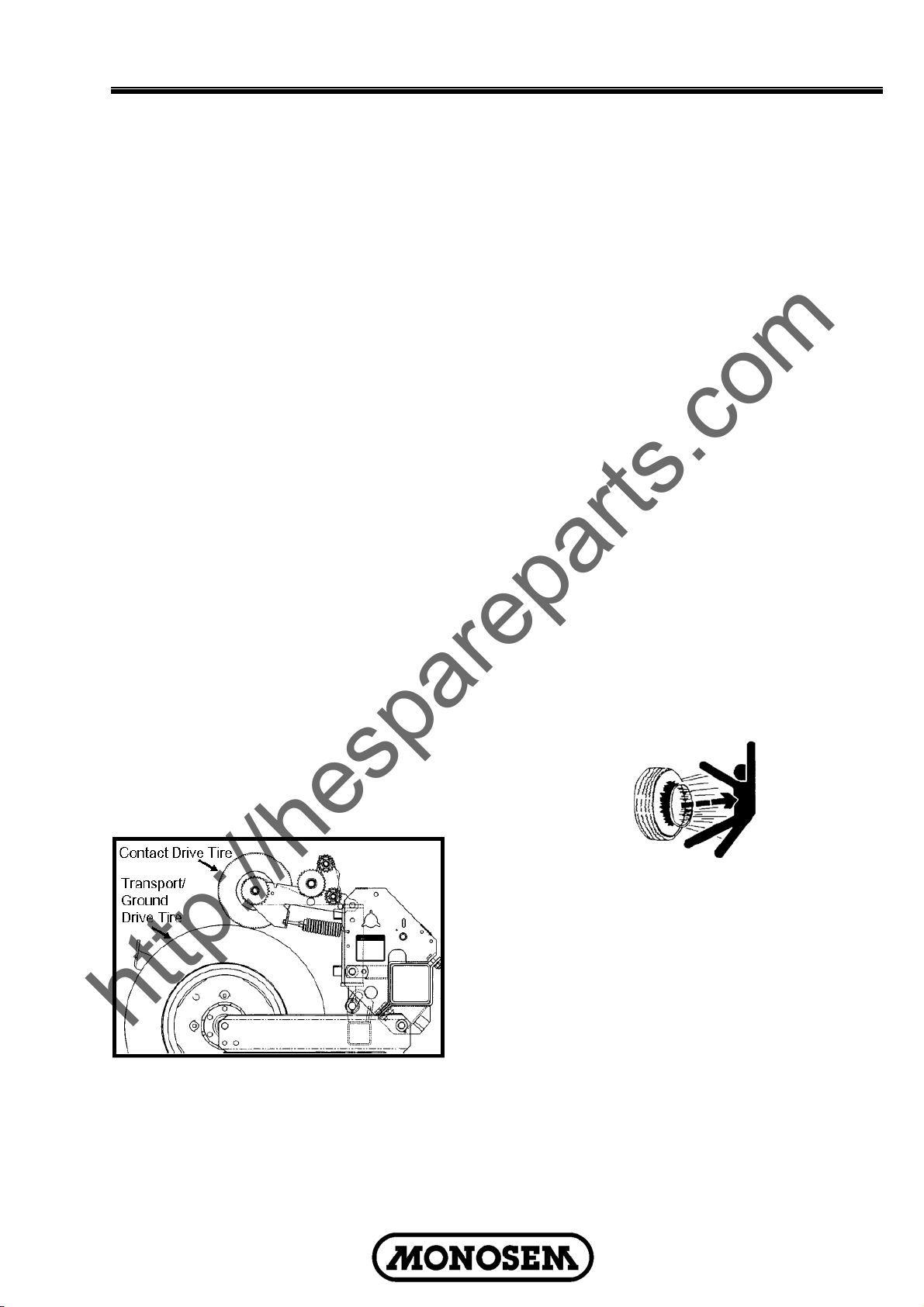
STANDARD RATE DRIVE
Seed planting rate charts are based on the
standard rate drive. The standard rate drive
uses a 30 tooth sprocket on each contact
drive tire.
IMPORTANT : After each sprocket
combination adjustment, make a field
check to be sure you planting at the
desired rate.
7
Page 10
Operation
http://hespareparts.com
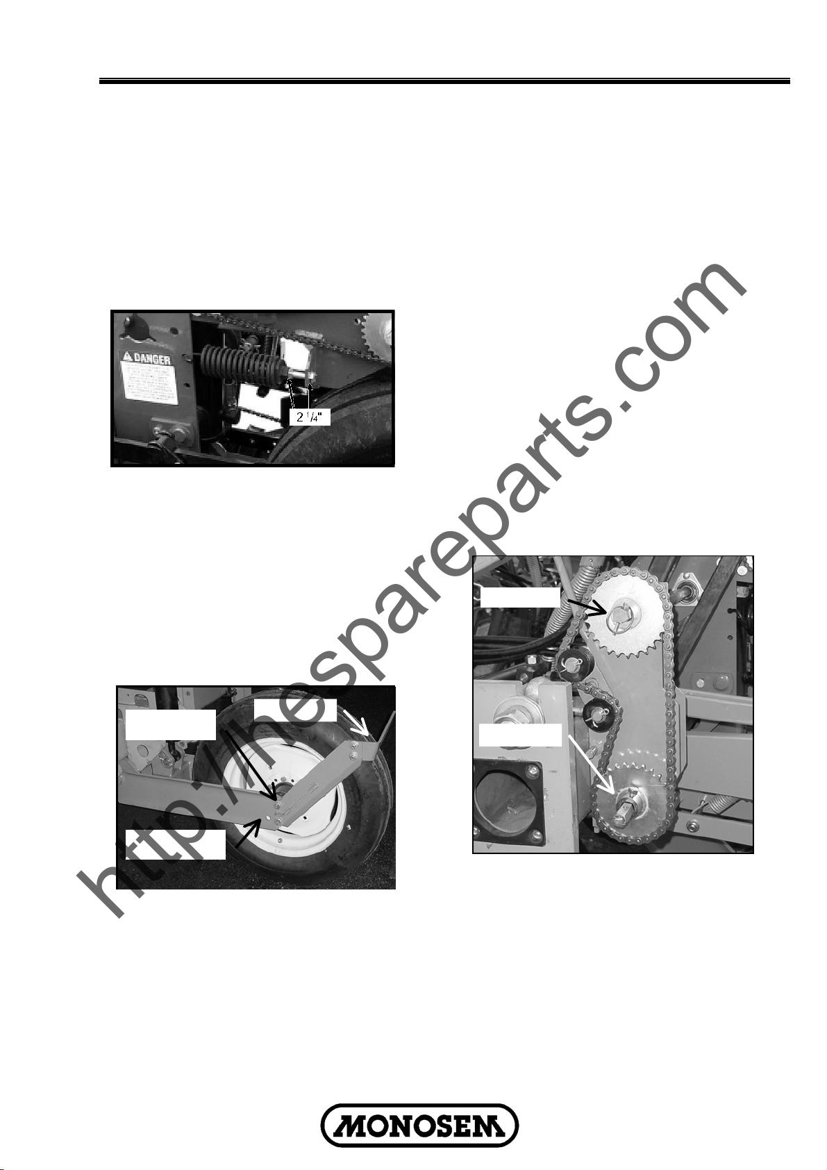
CONTACT DRIVE WHEEL SPRING
ADJUSTMENT
There are two down pressure springs on
each contact drive wheel. The down
pressure is factory pre-set and should need
no further adjustment.
The spring tension is set leaving 2 ¼"
between the spring plug and the bolt head.
TIRE SCRAPER
Due to the clearance between the wheel
assembly and the transport tire when a
planter is equipped with the 20" transport
tire, a tire scrapper should always be used.
This will help prevent a build-up of dirt/mud
between the wheel arm assembly and the
tire. Adjust the scrapper so it does not
contact the tire.
Standard 20" tire
RIDGE PLANTING
For ridge planting mount the 20" tires in the
lower rear holes in the ground drive wheel
arm to raise the bar height 3". Mount the
contact drive wheel arm and springs in the
lower set of mounting holes in the wheel
module mount and raise the hitch height to
maintain fore and aft levelness.
installation
For ridge planting
To raise bar height
Tire scraper
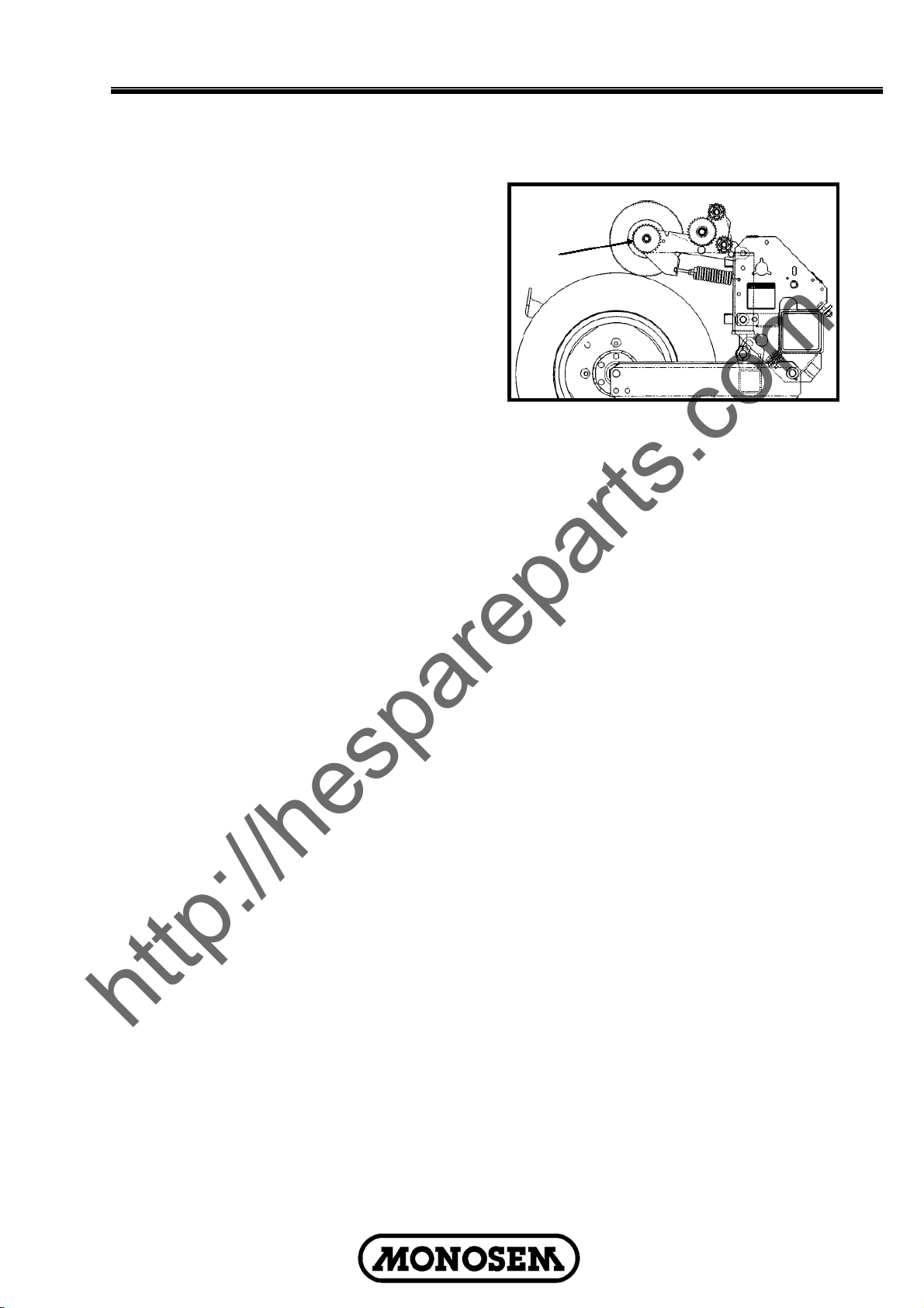
TRANSMISSION ADJUSTMENT
Planting population rate changes are made
at the end mounted transmission. The
planter is designed to allow simple, rapid
changes in sprockets to obtain the desired
planting population. By removing the lynch
pins on the hexagon shafts, sprockets can
be interchanged with those from the sprocket
storage rod bolted to the transmission.
Chain tension is controlled by a springloaded dual sprocket idler. The idler
assembly is adjusted with a ratchet arm. This
arm has a release position to remove spring
tension for replacing sprockets. The amount
of spring tension on the chain can be
controlled by the ratchet arm.
The planting rate chart on the following
pages of this section will aid you in selecting
the correct sprocket combinations.
Drive
Driven
8
Page 11

Operation
http://hespareparts.com
!
WARNING: Always make sure
safety/warning lights, reflectors and SMV
emblem are in place and visible prior to
transporting the machine on public
roads. In this regard, check federal,
state/provincial and local regulations.
!
WARNING: Always install safety
lockups on lift cylinders and make sure
wing lockup pins are in place to secure
wings at hitch.
TRACTOR PLANTING SEED
Planters are designed to operate within a
speed range of 2 to 8 mph. See “planting
and application rate charts”. Variations in
ground speed will produce variations in
rates.
NOTE : Due to a multitude of variables,
seed spacing can be adversely affected at
speeds above 5,5 mph.
METRIC CONVERSION TABLE
Multiply By To Get
Inches (in.) x 2.54 = centimeters (cm)
Inches (in.) x 25.4 = millimeters (mm)
Feet (ft.) x 30.48 = centimeters (cm)
Acres x 0.405 = hectares (ha)
Miles per hour x 1.609 = kilometers per
(mph) hour (Km/h)
Pounds (lbs.) x 0.453 = kilograms (kg)
Bushels (bu.) x 35.238 = liters (l)
Gallons (gal.) x 3.785 = liters (l)
Pounds per x 6.894 = kilopascals (kPa)
square inch (psi) (100 kPa = 1 bar)
Inch pounds x 0.113 = newtons-meters
(in. lbs.) (N•m)
Foot pounds x 1.356 = newtons-meters
(ft. lbs.) (N•m)
Centimeters x .394 = inches (in.)
(cm)
Millimeters x .0394 = inches (in.)
(mm)
Centimeters x .0328 = feet (ft.)
(cm)
Hectares (ha) x 2.469 = acres
Kilometers per x 0.621 = miles per hour
hour (Km/h) (mph)
Kilograms (kg) x 2.208 = pounds (lbs.)
Liters (l) x 0.028 = bushels (bu.)
Liters (l) x 0.264 = gallons (gal.)
Kilopascals x 0.145 = pounds per
(kPa) (100 kPa = 1 bar) square inch (psi)
Newtons-meters x 8.85 = inch pounds
(N•m) (in. lbs.)
Newtons-meters x 0.738 = foot pounds
(N•m) (ft. lbs.)
FIELD TEST
With any change of field and/or planting
conditions, seed size or planter adjustment,
we recommend a field test be made to
ensure proper seed placement and operation
of row units. See “Rate Charts”, “Checking
Seed Population”, and “Checking Granular
Chemical Application Rate” at end of this
section :
Check the planter for fore to aft and
lateral level operation. See “Leveling The
Planter”.
Check all row units to be certain they are
running level. When planting, the row
unit parallel arms should be
approximately parallel to the ground.
Check row markers for proper operation
and adjustment. See “Marker
Adjustment” and “Marker Speed
Adjustment”.
Check for proper application rates and
placement of granular chemicals on all
rows. See “Checking Granular Chemical
Application Rate”.
Check for desired depth placement and
seed population on all rows. See
“Checking Seed Population”.
After the planter has been field tested,
reinspect the machine :
Hoses and fittings
Bolts and nuts
Cotter pins and spring pins
Drive chain alignment
9
Page 12

Operation
http://hespareparts.com
TRANSPORT TO FIELD OPERATION
Hydraulic Wing Fold
WARNING : Be sure the planter is
on a level surface, fore and aft and side to
side. Avoid standing between the wing
and main frame when folding the planter.
Wing may swing suddenly.
SUMMARIZED TRANSPORT TO FIELD SEQUENCE
. With center lift cylinders retracted and lock ups in place
remove wing lock pins.
. Move selector valve to "fold" position.
. Hydraulically fold wings out.
. Swing wing locking bolts into place.
. Extend lift cylinders.
. Remove center section lift cylinder lockups.
. Lower planter.
. Tighten wing locking bolts.
. Release turnbuckle at center of planter.
. Move selector valve to "marker" position.
NOTE : Read the following information for more detailed
instructions.
1. If the wing lift tires are not retracted,
with the cylinder lockups in place on the four
center section lift cylinders, move the tractor
hydraulic lever to the lowering position until
the cylinders are fully retracted thus raising
the wing tires.
2. With the planter raised and the
cylinder lockups in place, remove the wing
lock pins at the marker support and hitch.
4. Move the tractor hydraulic lever and
fold the wings out to operating position.
5. Swing the wing locking bolts into
position to lock each wing.
6. Operate the hydraulic lever to extend
all the lift cylinders.
7. Remove the cylinder lockups from the
four center section lift cylinders and place
them in the storage position on the wheel
modules.
8. Lower the planter.
9. Using the special wrench which is
stored on the hitch of the planter, tighten the
¼" hex nuts to secure the wing locking bolts.
3. Position the selector handle on the
manual selector valve in the "fold" position.
10
10. Release the turnbuckle
located in the center of the planter frame,
using the special wrench, and fold it to one
side. Return wrench to the storage position
on the longue.
11. Move the selector handle on
the manual selector valve to the "marker"
position. (Remove pressure from the
hydraulic system before moving the selector
handle).
Page 13

Operation
http://hespareparts.com
MARKER SPEED ADJUSMENT
The marker hydraulic system includes two
flow control valves. One flow control valve
controls the lowering speed of both markers
and one controls the raising speed of both
markers. To adjust marker speed, loosen the
jam nut and turn the control(s) clockwise or
IN to slow the travel speed and counter
clockwise or OUT to increase the travel
speed. The flow controls determine the
amount of oil flow restriction through the
valves, therefore determining travel speed of
the markers.
MARKER ADJUSTMENT
To determine the correct length at which to
set the marker assemblies, multiply the
number of rows by the average row spacing
in inches. This provides the total planting
width. Adjust the marker extension so the
distance from the marker blade to the center
line of the planter is equal to the total
planting width previously obtained. Both the
planter and marker assembly should be
lowered to the ground when measurements
are being taken. The measurement should
be taken from the point where the blade
contacts the ground. Adjust right and left
marker assemblies equally and securely
tighten clamping bolts. An example of
marker length adjustment follows:
Number of rows x Row spacing inches = Dimension between
planter center line and marker blade.
16 Rows x 30" Spacing = 480" Marker Dimension
DANGER: The flow controls should be
properly adjusted before the marker
assembly is first put into use. Excessive
travel speed of the markers can be
dangerous and/or damage the marker
assembly.
NOTE: When oil is cold, hydraulics
operate slowly. Make sure all adjustments
are made with warm oil.
NOTE: On a tractor where the oil flow can
not be controlled, the rate of flow of oil
from the tractor may be greater than the
rate at which the marker cylinder can
accept it. The tractor hydraulic control
lever will have to be held until the
cylinder reaches the end of its stroke.
This occurs most often on tractors with
an open center hydraulic system.
On tractors with a closed center hydraulic
system, the tractor's hydraulic flow
control can be set so the tractor's detent
will function properly.
The marker blade is installed so the concave
side of the blade is outward to throw dirt
away from the grease seals. The spindle
bracket is slotted so the hub and blade can
be angled to throw more or less dirt. To
adjust the hub and spindle, loosen the 1/2"
mounting hardware and move the bracket as
required. Tighten bolts to the specified
torque.
IMPORTANT: A marker blade assembly
that is set at a sharper angle than
necessary will add unnecessary stress to
the complete marker assembly and
shorten the life of bearings and blades.
Set the blade angle only as needed to
leave a clear mark.
A field test is recommended to ensure the
markers are properly adjusted. After the field
test is made, make any minor adjustments
as necessary.
11
Page 14

Operation
http://hespareparts.com
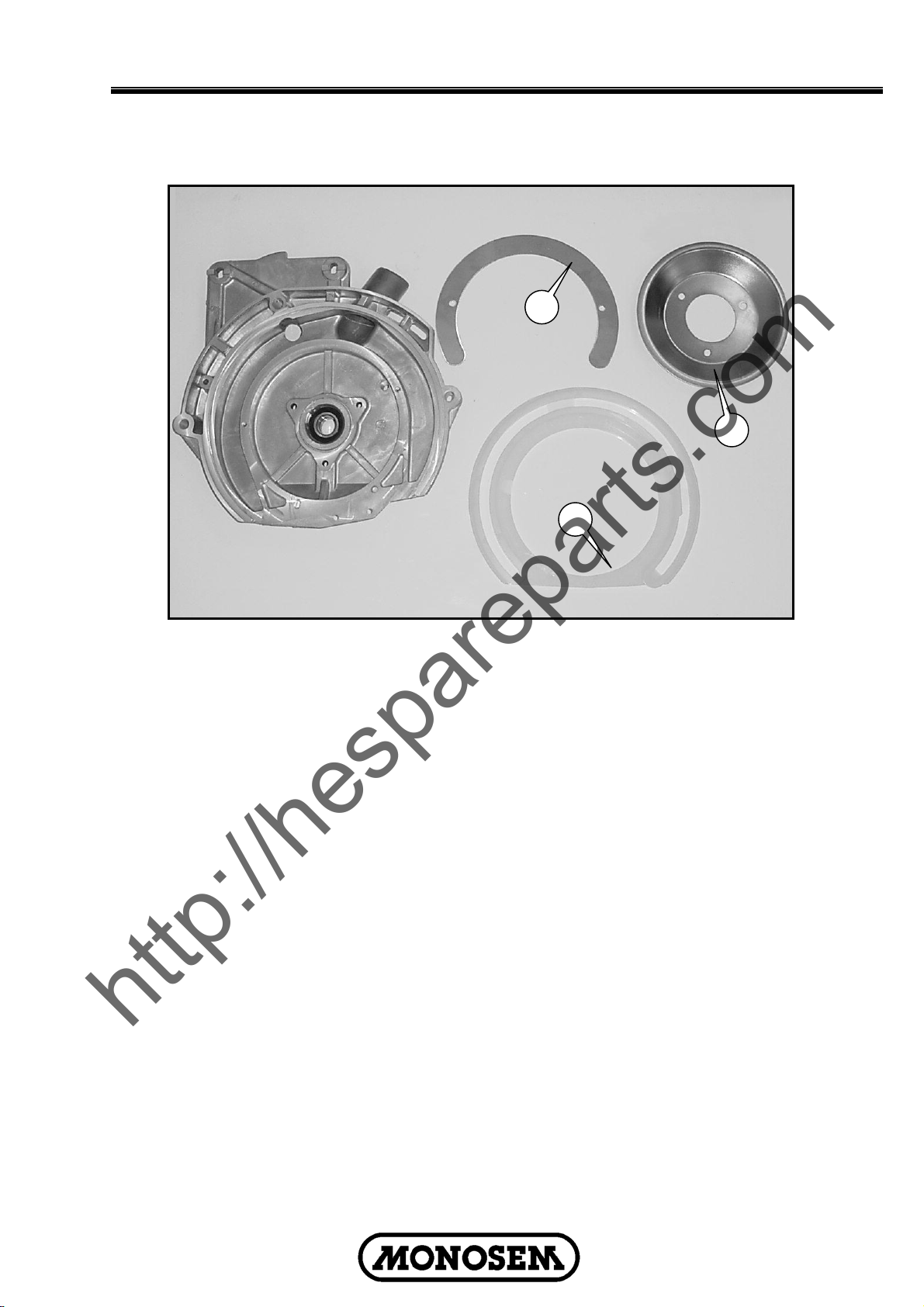
PLANTER METERING UNIT NG PLUS 2
The NG Plus 2 metering unit in fig. 40 is
shown with standard features. Other options
are available for specific conditions or uses.
The drive chain is mounted as per fig. 41.
The individual disengaging of a metering unit
is possible by removing the lynch pin (rep.1)
of by disconnecting the vacuum hose.
The seed depth is adjusted by the
handwheel (rep.2) which changes the height
of the 2 depth wheels (rep.3) in relation to
the furrow disc openers (rep.4). A sticker
close to the handwheel, provided with a
gradual scale, ensures the uniformity of the
depth control on all row units of the planter.
The furrow opener and ground adjustment
system guarantees an accurate and regular
seed depth in all types of soil and conditions
because the depth wheels are positioned
perpendicular to the falling point of seeds.
The two rear press wheels (rep.5) affect only
the closing of the seed furrow. They float
independently and therefore do not have any
effect on the ground engaging. Their soil
pressure is regulated by the handwheel
(rep.6). This pressure has to be chosen
carefully in order to assure proper seed to
soil contact. Soil should be pressed over the
complete length of the row. This setting
depends on the type and humidity of the soil.
In order for the furrow disc opener to remain
properly cleaned, the 2 gauge wheels (rep.3)
have to touch (without pinching their outside
circumference). After starting up the planter,
the factory assembly may need
readjustment.
Adjust gauge wheel spacing by putting the
washers (rep.7) from one side of the
articulating arms to the other.
Adjust the pressure of the scrapers of discs
by tightening or loosening the bolts (rep.8).
Before and during each new planting
season, check if the seed tubes (rep.9) are
in good condition as consistent and regular
seeding will depend on this. Do not hesitate
to replace them if they are worn or damaged.
To replace them, remove pin (rep.10) after
removing the gauge wheel and furrow disc
opener on one side (Fig.42).
The function of clod removers (rep.11) is to
clear the surface of the soil but not to plow a
furrow. One use of the front brace of the clod
remover is to slice open hard soil and move
stones away from the track of the disc
opener. They need to be adjusted
accordingly. Using them in stony soils may
be a problem because they can cause
clogging and blocking. In this case it is better
to choose an assembly with a flexible
support bracket (fig. 43) which is efficient in
difficult soil conditions.
Fig.43
12
Page 15

Operation
http://hespareparts.com
2
7
6
4
35
11
Fig.40
10
8
9
Fig.41 Fig.42
13
Page 16
Operation
http://hespareparts.com
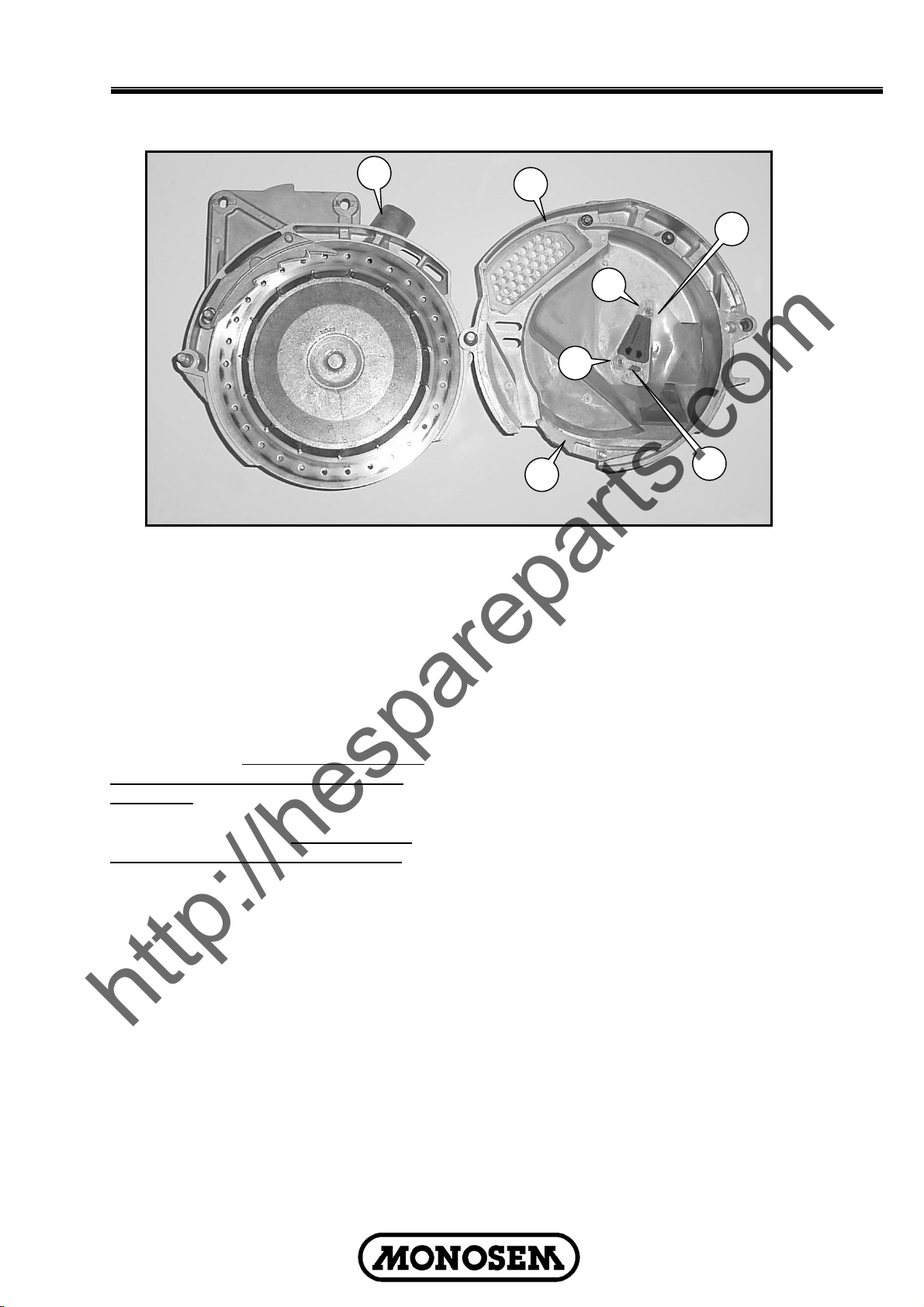
METERING BOX
7
6
5
The plastic wear gasket 5 on which the seed
disc rotates should be smooth and in good
condition. Under normal operating
conditions, it should be replaced only after
500 to 1000 ha (1250 to 2500 acres). The
metal brace 7 should be positioned with its
tab notched in the hole of the housing. The
outer edge of the plastic wear gasket is then
rotating , and is then held in position by cup
6 and 3 bolts. (Fig.33)
NOTE : Thoroughly clean the metering
box housing, before installing a new wear
gasket. Any residue left from previous
use will not allow the gasket to fit in the
proper position.
Fig.33
SUGGESTED SEED DISC USE
Crop Seed disc
Corn DC1850-Low population
DC2450-Medium population
DC3050-High population
Sunflower DC1225-Low population
(Oils & confection)
DC1825-High population
(Oils & confection)
14
Page 17
Operation
http://hespareparts.com
A
A sheet metal shutter 1 is mounted inside
the cover B. This shutter regulate the flow of
seeds coming from the hopper and provide a
constant and sufficient level in front of the
disc. According to the seed used, the shutter
as to be checked and adjusted at 2 different
positions before planting:
1. High position : For large seeds such as
corn , soybean, edible beans, peanuts,
cotton, etc.
2.Low position (fig.35) : For small seeds
such as sunflower, beet, sorghum, etc.
This position should also be used for large
seeds when the planter has to work for
several hundred meters (1000 or more) on
slopes of more than 20%.
The shutter is adjusted by lowering it after
loosening the two bolts 2. A small plastic
sheet 3 located under the shutter is also
used to limit the level of seeds in front of the
disc .
Before beginning your season, make sure
that it is in good condition.
B
3
2
2
4
A special metering box cover with a larger
opening (to improve the seed flow into the
seed chamber), a large discharge channel
(to avoid blockage) , and a special less
aggressive seed scraper (to avoid skips) are
available for the planting of large seeds such
as peanuts, kidney beans and large squash.
1
Fig.35
A special metal shutter is available for
planting small seeds such as cabbage ,
rape seed, etc. to reduce the seed flow into
the seed chamber.
A special ejector block maybe needed to
eliminate bridging in the discharger channel
in the cover for large peanuts and large
squash seed.
The ejector block 4 enables the seeds to fall
regularly. For this purpose, it is
recommended to check its conditions
periodically.
15
Page 18
Operation
http://hespareparts.com
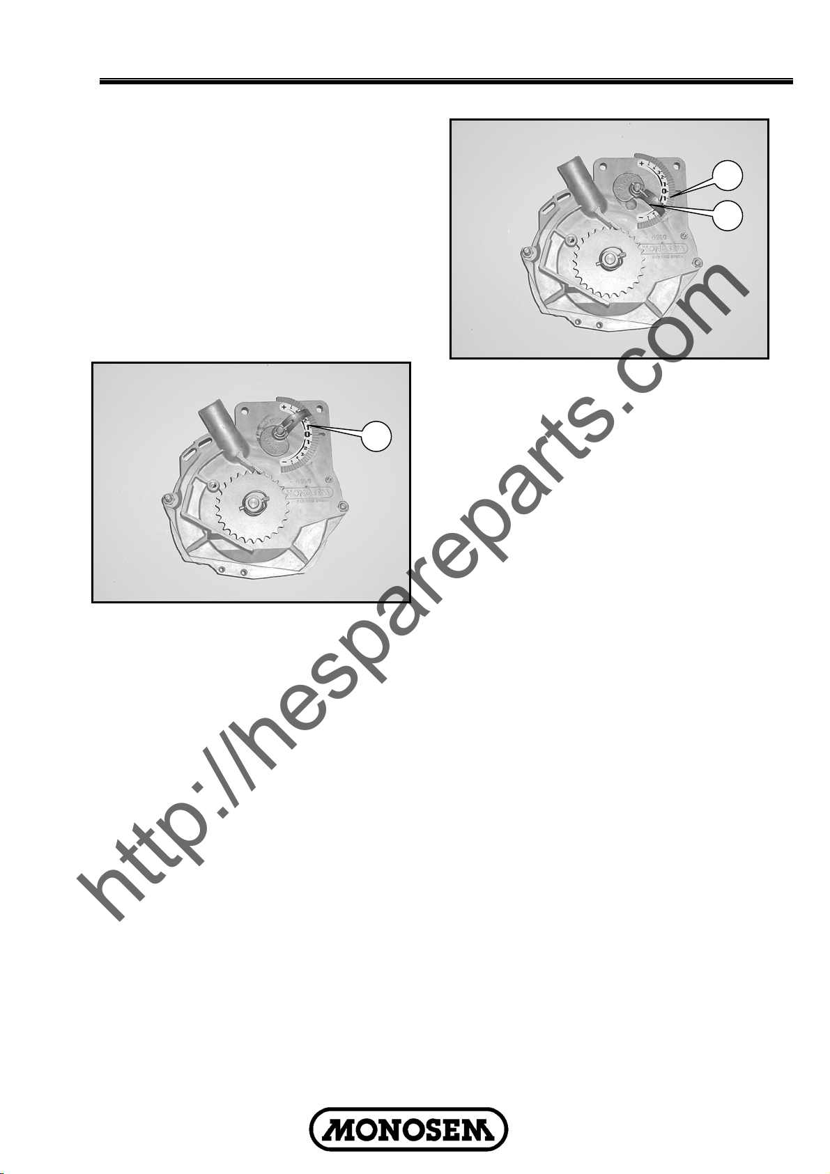
METERING ADJUSTMENT
Two factors influence the degree of seed:
1.The position of the seed scraper in relation
to the holes of the disc. It is therefore
necessary to adjust the eight of the scraper
as needed for each seed type.
2.The degree of suction (depression) at the
seed disc. It is therefore necessary to adjust
the degree of suction to the weight of the
seed to be planted;
1
Fig.36
The (patented) MONOSEM system allows a
unique adjustment (fig. 36-37).
• To adjust the height of the scraper
and at the same time
• To adapt the degree of suction to the
weight and size of the seed.
1
2
Fig.37
When the indicator 1 is positioned to the “+”
(fig 36) it raises the scraper over the holes of
the disc and increases the degree of suction
(closing the size of the hole 2) . This may
cause doubles if raised too high.
When the indicator 1 is positioned to (fig 37).
It lower the scraper over the holes and
reduces the degree of suction (opening the
size of the hole 2) . This may cause skipping
if too low.
A control window in the cover allows you to
monitor the results.
16
Page 19

Operation
http://hespareparts.com
TRANSMISSION ADJUSTMENT
Planting population rate changes are made
at the end mounted transmission. The
planter is designed to allow simple, rapid
changes in sprockets to obtain the desired
planting population. By removing the lynch
pins on the hexagon shafts, sprockets can
be interchanged with those from the sprocket
storage rod bolted to the transmission.
Chain tension is controlled by a springloaded dual sprocket idler. The idler
assembly is adjusted with a ratchet arm. This
arm has a release position to remove spring
tension for replacing sprockets. The amount
of spring tension on the chain can be
controlled by the ratchet arm.
The planting rate chart on the following
pages of this section will aid you in selecting
the correct sprocket combinations.
OPTIONAL EQUIPMENT
An optional hydraulic drive for the turbofan is
available. You must then double check that
there is adequate oil flow for the turbofan to
run at 500 rpm. Use an rpm gauge to check,
placing it at the center of the lower pulley.
A vacuum gauge may also be mounted to
the turbofan. (The vacuum gauge is standard
equipment when ordering the hydraulic
drive).
17
Page 20
Operation
http://hespareparts.com
SOWING DISTANCES
Planting distances obtained with standard
assembly and sprocket system.
IMPORTANT : Make sure the chains are
tight and properly lubricated, and tires
are properly inflated.
The above indicated spacings are
theoretical and may vary from 5-10 %
depending on soil conditions.
Check proper working of the seed
metering, seed placement, spacing and
density when starting up and from time to
time during planting.
The following drawings show the two
possibilities of wheel unit mounting.
30 toothed drive sprocket with 23 toothed
driven sprocket:
8"
30
1
23
30
23 toothed drive sprocket with 30 toothed
driven sprocket:
8"
23
15
A
18
B
26
2
30
30
15
A
18
B
26
18
Page 21
Operation
http://hespareparts.com
TRANSMISSION SELECTION
The seed spacing is shown in cm
B=28
Number of holes in
the seed disc
24 Sunflower
30 Corn
60 Soybean
Number of holes in
the seed disc
24 Sunflower
30 Corn
60 Soybean
Drawing N°1 30/23
A
27 25 24 23 21 19 17 15
28 28 28 28 28 28 28 28
B
12,7 13,7 14,3 14,9 16,4 18,1 20,2 22,9
10,2 11,0 11,5 12,0 13,1 14,5 16,2 18,3
5,1 5,5 5,7 6,0 6,5 7,2 8,1 9,2
Drawing N°2 23/30
27 25 24 23 21 19 17 15
A
28 28 28 28 28 28 28 28
B
21,7 23,4 24,4 25,4 27,8 30,8 34,4 39,0
17,3 18,7 19,5 20,3 22,3 24,6 27,5 31,2
8,7 9,4 9,7 10,2 11,1 12,3 13,8 15,6
B=27
Number of holes in
the seed disc
24 Sunflower
30 Corn
60 Soybean
Number of holes in
the seed disc
24 Sunflower
30 Corn
60 Soybean
Drawing N°1 30/23
A
28 25 24 23 21 19 17 15
27 27 27 27 27 27 27 27
B
11,8 13,3 13,8 14,4 15,8 17,4 19,5 22,1
9,5 10,6 11,0 11,5 12,6 14,0 15,6 17,7
4,7 5,3 5,5 5,8 6,3 7,0 7,8 8,8
Drawing N°2 23/30
A
28 25 24 23 21 19 17 15
27 27 27 27 27 27 27 27
B
20,1 22,6 23,5 24,5 26,8 29,7 33,2 37,6
16,1 18,0 18,8 19,6 21,5 23,7 26,5 30,1
8,1 9,0 9,4 9,8 10,7 11,9 13,3 15,0
19
Page 22

Operation
http://hespareparts.com
B=25
Number of holes in
the seed disc
24 Sunflower
30 Corn
60 Soybean
Number of holes in
the seed disc
24 Sunflower
30 Corn
60 Soybean
Drawing N°1 30/23
A
28 27 24 23 21 19 17 15
25 25 25 25 25 25 25 25
B
11,0 11,4 12,8 13,3 14,6 16,1 18,0 20,5
8,8 9,1 10,2 10,7 11,7 12,9 14,4 16,4
4,4 4,5 5,1 5,3 5,8 6,5 7,2 8,2
Drawing N°2 23/30
28 27 24 23 21 19 17 15
A
25 25 25 25 25 25 25 25
B
18,6 19,3 21,8 22,7 24,9 27,5 30,7 34,8
14,9 15,5 17,4 18,2 19,9 22,0 24,6 27,8
7,5 7,7 8,7 9,1 9,9 11,0 12,3 13,9
B=24
Number of holes in
the seed disc
24 Sunflower
30 Corn
60 Soybean
Number of holes in
the seed disc
24 Sunflower
30 Corn
60 Soybean
Drawing N°1 30/23
A
28 27 25 23 21 19 17 15
24 24 24 24 24 24 24 24
B
10,5 10,9 11,8 12,8 14,0 15,5 17,3 19,6
8,4 8,7 9,4 10,2 11,2 12,4 13,9 15,7
4,2 4,4 4,7 5,1 5,6 6,2 6,9 7,9
Drawing N°2 23/30
28 27 25 23 21 19 17 15
A
24 24 24 24 24 24 24 24
B
17,9 18,6 20,0 21,8 23,9 26,4 29,5 33,4
14,3 14,8 16,0 17,4 19,1 21,1 23,6 26,7
7,2 7,4 8,0 8,7 9,5 10,6 11,8 13,4
20
Page 23

Operation
http://hespareparts.com
B=23
Number of holes in
the seed disc
24 Sunflower
30 Corn
60 Soybean
Number of holes in
the seed disc
24 Sunflower
30 Corn
60 Soybean
Drawing N°1 30/23
A
28 27 25 24 21 19 17 15
23 23 23 23 23 23 23 23
B
10,1 10,5 11,3 11,8 13,4 14,9 16,6 18,8
8,1 8,4 9,0 9,4 10,8 11,9 13,3 15,1
4,0 4,2 4,5 4,7 5,4 5,9 6,6 7,5
Drawing N°2 23/30
28 27 25 24 21 19 17 15
A
23 23 23 23 23 23 23 23
B
17,2 17,8 19,2 20,0 22,9 25,3 28,3 32,0
13,7 14,2 15,4 16,0 18,3 20,2 22,6 25,6
6,9 7,1 7,7 8,0 9,1 10,1 11,3 12,8
B=21
Number of holes in
the seed disc
24 Sunflower
30 Corn
60 Soybean
Number of holes in
the seed disc
24 Sunflower
30 Corn
60 Soybean
Drawing N°1 30/23
A
28 27 25 24 23 19 17 15
21 21 21 21 21 21 21 21
B
9,2 9,5 10,3 10,7 11,2 13,6 15,2 17,2
7,4 7,6 8,2 8,6 9,0 10,9 12,1 13,7
3,7 3,8 4,1 4,3 4,5 5,4 6,1 6,9
Drawing N°2 23/30
28 27 25 24 23 19 17 15
A
21 21 21 21 21 21 21 21
B
15,7 16,2 17,5 18,3 19,1 23,1 25,8 29,2
12,5 13,0 14,0 14,6 15,3 18,5 20,6 23,4
6,3 6,5 7,0 7,3 7,6 9,2 10,3 11,7
21
Page 24

Operation
http://hespareparts.com
Densities - Seed Population Chart
AVERAGE
SEED
SPACING (cm)
5
6
7
8
9
10
11
12
13
14
15
16
ROW SPACING (cm)
45 50 70 75 76,2 80
(30")
444444 400000 285714 266667 262467 250000
370370 333333 238095 222222 218723 208333
317460 285714 204082 190476 187477 178571
277778 250000 178571 166667 164042 156250
246914 222222 158730 148148 145815 138889
222222 200000 142857 133333 131234 125000
202020 181818 129870 121212 119303 113636
185185 166667 119048 111111 109361 104167
170940 153846 109890 102564 100949 96154
158730 142857 102041 95238 93738 89286
148148 133333 95238 88889 87489 83333
138889 125000 89286 83333 82021 78125
17
18
19
20
21
Seed population per ha :
D = Seed population per ha (Seed/ha)
I = Row spacing (m)
E = Seed spacing (m)
D = 10.000
I x E
Example : D = 10.000
0,75 x 0,13
130719 117647 84034 78431 77196 73529
123457 111111 79365 74074 72908 69444
116959 105263 75188 70175 69070 65789
111111 100000 71429 66667 65617 62500
105820 95238 68027 63492 62492 59524
= 102.564 Seed/ha
Seed spacing :
D = Seed population per ha (Seed/ha)
I = Row spacing (m)
E = Seed spacing (m)
E = 10.000
I x D
Example : D = 10.000
90.000 x 0,75
= 0,148 m (14,8 cm)
22
Page 25

Operation
http://hespareparts.com
FERTILIZER
Gearbox for fertilizer low adjustment. See
following page for adjustments.
Linking tube to be disconnected for the
folding of the planter.
175 litres hopper for 2 rows.
Double discs for fertilizer. To be
positionned at 6 – 8 cms from the sowing
line.
23
Page 26

Operation
http://hespareparts.com
FERTILIZER
I Set on A1 adjustment.
II Make 100 m
III Use the following formula :
10000
inter-row spacing (cm)
You obtain the weight/ha. And then you determine the column
on the chart corresponding to the ratio used.
Example
- weight calculated = 533 gr. On ratio 1
10000
76,2
The column
350 kg/ha according to the adjustment.
40 50 60
A1
45 60 70
B1
60 80 95
C1
70 90 110
D1
75 100 120
A2
80 105 130
E1
100 120 140
B2
110 140 165
F1
120 160 180
C2
140 180 210
D2
160 200 250
E2
200 250 300
F2
By means of an initial adjustment (A1) for a known surface area, calculate the minimum requirement
per hectare for the fertilizer used : 80-90-100-110 etc … kilo/ha. The table will then give the setting
(A1-B1-C1…) suitable for the required amount per hectare.
IMPORTANT
to different brands, temperature, humidity, etc… check your manual for procedure to measure your
fertilizer to the above chart.
WARNING
animals and soil. Handle with care and follow instructions of chemical manufacturer.
x weight calculated on one outlet (gr)
: - Inter-row spacing = 30" = 76,2 cm
x 533 = 70.000 gr/ha = 70 kg/ha
4 is used = 70 kg/ha, with a choice from 70 to
Requirement per Hectare for different fertilizers
– Fertilizer application rates can vary from the weight calculated in the above chart due
- Agricultural chemicals can be dangerous. Improper use can result in injury to persons,
4
70
80
110
125
135
145
160
190
210
240
280
350
80 90 100 110 120 130
90 105 115 125 140 150
120 140 160 175 190 205
140 160 180 195 215 230
150 175 190 210 230 250
160 185 205 230 250 270
180 205 230 250 275 300
215 245 270 300 325 350
235 270 300 330 360 390
270 310 340 380 410 445
315 360 400 440 480 520
390 450 500 550 600 650
24
Page 27

Operation
http://hespareparts.com
MICROSEM
The Microsem is ground driven, and the
output set by means of a transmission which
is unaffected by a change in planting speed.
The Microsem system is mounted to the
toolbar frame to reduce weight on the planter
unit. Each Microsem hopper has an 18 lt.
capacity
Setting of the output = the output is a
function of the number of rotations of the
spindle of the metering boxes. The drive
system is a central drive system which is set
primarily with the double sprocket and the
interchangeable sprockets the Microsem
setting chart will assist with the setting and
also indicates the sprockets to be used.
Gearbox assembly
Microsem hopper assembly
Microsem hopper assembly
Microsem tube assembly
ATTENTION : Avoid moisture
contamination. This unit should be used
only with microgranulars and not with
powders or granulates. Agricultural
chemicals can be dangerous. Improper
use can result in injury to persons,
animals and soil. Handle with care and
follow instructions of chemical
manufacturer.
25
Page 28

Operation
http://hespareparts.com
MICROSEM ADJUSTMENT
1. Put the product in a 2 outlet microgranulator.
2. Position in smallest ration : A = 12
B = 30 (ratio = 0.24- see here under)
C = 12
3. Make 100 m.
4. Weigh the product recuperated on the two outlets.
5. Use the following formula :
Output = 10 x quantity weighed (g.)
Inter-row (cm) x 2
Example : Inter-rows = 60 cm Output = 10 x 60
Quantity weighed = 60 g 60 x 2
If you require 10 Kg/ha, choose the ratio
2 x 0.24 = 0.48
i.e. : A = 12
If you require 15 Kg/ha, choose the ratio
3 x 0.24 = 0.72
i.e. : A = 12
B = 15
C = 12
Note : Checking when starting up remains essential.
Possible combinations of the sprockets A-B-C Obtained ratios
12-35-12 teeth 0.21
12-32-12 teeth 0.22
12-30-12 teeth 0.24
12-25-12 teeth 0.29
12-22-12 teeth 0.33
12-20-12 teeth 0.36
12-18-12 teeth 0.40
12-16-12 teeth 0.45
12-15-12 teeth or 12-25-20 0.48
12-23-20 teeth 0.51
12-22-20 teeth 0.54
12-21-20 teeth 0.57
12-12-12 teeth 0.60
25-24-12 teeth 0.63
12-18-20 teeth 0.66
25-22-12 teeth 0.68
12-10-12 teeth 0.72
25-20-12 teeth 0.75
12-15-20 teeth 0.80
25-18-12 teeth 0.83
25-16-12 teeth 0.94
25-15-12 teeth or 12-12-20 1
25-22-20 teeth 1.13
12-10-20 teeth 1.2
25-12-12 teeth 1.25
25-18-20 teeth 1.4
25-10-12 teeth 1.5
25-15-20 teeth 1.66
25-12-20 teeth 2.08
25-10-20 teeth 2.5
The interchangeable sprockets B in bold characters are delivered as standard (12-15-18-22-
25-30 teeth), those in ordinary characters are delivered on request (10-11-13-14-16-17-19-20-2123-24-26-27-32-35 teeth).
(N° Microsem shaft rotations for 1 leading shaft rotation)
= 5 Kg/ha
B = 15
The nearest standard
C = 20
Less product
More product
26
Page 29

Lubrication
http://hespareparts.com
WHEEL BEARINGS
All wheel bearings should be repacked
annually and checked for wear. This applies
to all drive wheels, transport wheels and
marker hubs. To check for wear, lift the
wheel off the ground. Check for endplay in
the bearings by moving the tire in and out.
Rotate the tire to check for roughness in the
bearings. If bearings sound rough, the hub
should be removed and the bearings
inspected and replaced if necessary. See
“Wheel Bearing Lubrication or
Replacement”. To repack wheel hubs, follow
the procedure outlined for wheel bearing
replacement with the exception that bearings
and bearing cups are reused.
!
DANGER: Always install safety
lockups or lower to the ground before
working under or around the machine.
NOTE: Numbers on below illustration
correspond to photos on following pages
showing lubrication frequencies.
GREASE FITTINGS
Those parts equipped with grease fittings
should be lubricated at the frequency
indicated with an SAE multipurpose type
grease. Be sure to clean the fitting
thoroughly before using grease gun. The
frequency of lubrication recommended is
based on normal operating conditions.
Severe or unusual conditions may require
more frequent attention.
1
7 7
3
6 4
5
1
3
2
2 2 2
2 2 2 2
27
Page 30

Lubrication
http://hespareparts.com
The following pages show the locations of all
lubrication points. Proper lubrication of all
moving parts will help ensure efficient
operation of your MONOSEM planter and
prolong the life of friction producing parts.
!
lockups or lower to the ground before
working under the machine.
LUBRICATION SYMBOLS
Lubricate at frequency indicated with an SAE
multipurpose type grease.
Lubricate at frequency indicated with a high
quality SAE 10 weight oil or a quality spray
lubricant.
DANGER : Always install safety
Weekly
Weekly
Daily
Daily
DRIVE CHAINS
All transmission and drive chains should be
lubricated daily with a high quality SAE 10
weight oil or a quality spray lubricant.
Extreme operating conditions such as dirt,
temperature or speed may require more
frequent lubrication. If a chain become stiff, it
should be removed, soaked and washed in
solvent to loosen and remove dirt from the
joints. Then soak the chain in oil so the
lubricant can penetrate between the rollers
and bushings.
Contact drive chain
Jack shaft chain
28
Page 31

Lubrication
http://hespareparts.com
1.Marker Assemblies : 3 Greasers per
assembly.
4. Center frame flex pin : 4 Greasers.
2. Wheel pivots : 2 Greasers per wheel
module.
3. Wing hinges : 2 Greasers per wing.
5. Hitch flex pin : 3 Greasers.
6. Turnbuckle : 1 Greaser.
7. Transmission Assemblies: 1 Greaser
(Idler).
29
Page 32

Maintenance
http://hespareparts.com
MARKER SEQUENCING/FLOW CONTROL
VALVE INSPECTION
The valve block assembly consists of the
marker sequencing and flow control valves in
one assembly. The sequencing valve portion
consists of a chambered body containing a
spool and series of check valves to direct
hydraulic oil flow. Should the valve
malfunction, the components may be
removed for inspection.
1. Remove valve block assembly from
planter.
2. Remove detent assembly and port
adapter assemblies from rear of valve
block.
IMPORTANT: Damage to the spool may
occur if the detent assembly and port
adapter assemblies are not removed prior
to removal of the spool.
3. Remove plug from both sides of valve
block and remove spool.
4. Inspect all parts for pitting, contamination
or foreign material. Also check seating
surfaces inside the valve. Replace any
parts found to be defective.
5. Lubricate spool with a light oil and re-
install. Check to be sure spool moves
freely in valve body.
IMPORTANT: Make sure correct check
ball(s) and spring are installed in each
valve bore upon reassembly.
A flow control valve is located on each side
of the block assembly. The flow control
valves should be adjusted for raise and
lower speed as part of the assembly
procedure or upon initial operation. If the
valve fails to function properly or requires
frequent adjustment, the needle valve should
be removed for inspection. Check for foreign
material and contamination. Be sure needle
moves freely in adjustment screw. Replace
any components found to be defective.
NOTE: When oil is cold, hydraulics
operate slowly. Make sure all adjustments
are made with warm oil.
30
Page 33

Maintenance
http://hespareparts.com
TROUBLE SHOOTING AND CAUSES
Excessive skipping :
• Transfer scraper too low (incorrect
setting on indicator).
• Transfer scraper is bent (no flat).
• Seed disc is bend or worn.
• Transfer scraper is dirty with chemical
product.
• Plastic wear surface of metering box
warped or used up.
• Holes of seed disc too small (do not
match).
• Holes of seed clogged (sugarbeets,
rapeseed, cabbage). To be double
checked from time to time.
• Excessive working speed.
• Defective vacuum hoses.
• Insufficient vacuum suction.
• PTO speed is to low.
• Foreign material mixed with seed.
• Seed blockage in the hopper (seed
treatment product too moist).
• Fan belt is too loose.
Excessive Doubling :
• Transfer scraper too high (bad setting on
indicator).
• Transfer scraper worn.
• Holes seed disc too large (do not fit).
• Excessive PTO speed.
• Excessive working speed.
• Seed level too high in the metering box.
Irregular Seeding (skipping-doubles) :
• Excessive working speed.
• Holes of seed disc too large (cut off
seeds).
• Field are too steep.
• Shutter adjusted incorrectly.
• Ejector is damaged.
Irregular spacing :
• Excessive working speed.
• Soil too wet and stricking to drive wheel
tires.
• Incorrect tire pressure
• Shutter adjusted incorrectly.
Safety slipcluch is actived :
• Seizing of metering box
• Foreign material in the seed.
• Blockage in transmission units.
Fertilizer :
• Foreign material in fertilizer.
• Clods/clumps in fertilizer.
• Clogging of outlet or chute caused by
moisture.
• Auger is defective (warped).
Microsem (Output varies between chutes
and cases) :
• Foreign material mixed with product.
• Attention : moisture in product.
• Improper assembly of metering unit
(auger reversed).
• Outlet chute unit warped.
• Hose clogged because too long or bent.
31
Page 34

Maintenance
http://hespareparts.com
32
Page 35

Maintenance
http://hespareparts.com
* Operate hydraulics slowly to accentuate the problem . Rephase after each lowering cycle.
33
Page 36

Maintenance
http://hespareparts.com
MARKER BEARING LUBRICATION OR
REPLACEMENT
1. Remove marker blade.
2. Remove dust cap from hub.
3. Remove cotter pin, nut and washer.
4. Slide hub from spindle.
5. Remove bearings and cups and discard
if bearings are being replaced. Clean hub
and dry. Remove bearings only and not
cups if repacking.
6. Press in new bearing cups with thickest
edge facing in. (Bearing replacement
procedure only.)
7. Pack bearings with heavy duty wheel
bearing grease thoroughly forcing grease
between roller cone and bearing cage.
Also fill the space between the bearing
cups in the hub with grease.
8. Install rubber seal into grease seal. Place
inner bearing in place and press in new
rubber seal/grease seal.
9. Clean spindle and install hub.
10. Install outer bearing, washer and slotted
hex nut. Tighten slotted hex nut while
rotating hub until there is some drag.
This assures that all bearing surfaces are
in contact. Back off slotted nut to nearest
locking slot and install cotter pin.
11. Fill dust caps approximately 3/4 full of
wheel bearing grease and install on hub.
12. Install blade and dust cap retainer on
hub and tighten evenly and securely.
WHEEL BEARING LUBRICATION OR
REPLACEMENT
1. Raise tire clear of ground and remove
wheel.
2. Remove double jam nuts and slide hub
from spindle.
3. Remove bearings and cups and discard
if bearings are being replaced. Clean hub
and dry. Remove bearings only and not
cups if repacking.
4. Press in new bearing cups with thickest
edge facing in. (Bearing replacement
procedure only.)
5. Pack bearings with heavy duty wheel
bearing grease thoroughly forcing grease
between roller cone and bearing cage.
Also fill the space between the bearing
cups in the hub with grease.
6. Place inner bearing in place.
7. Clean spindle and install hub.
8. Install outer bearing and jam nut. Tighten
jam nut while rotating hub until there is
some drag. This assures that all bearing
surfaces are in contact. Back off jam nut
1/4 turn or until there is only slight drag
when rotating the hub. Install second jam
nut to lock against first.
9. Install wheel on hub and tighten evenly
and securely.
34
Page 37

Maintenance
http://hespareparts.com
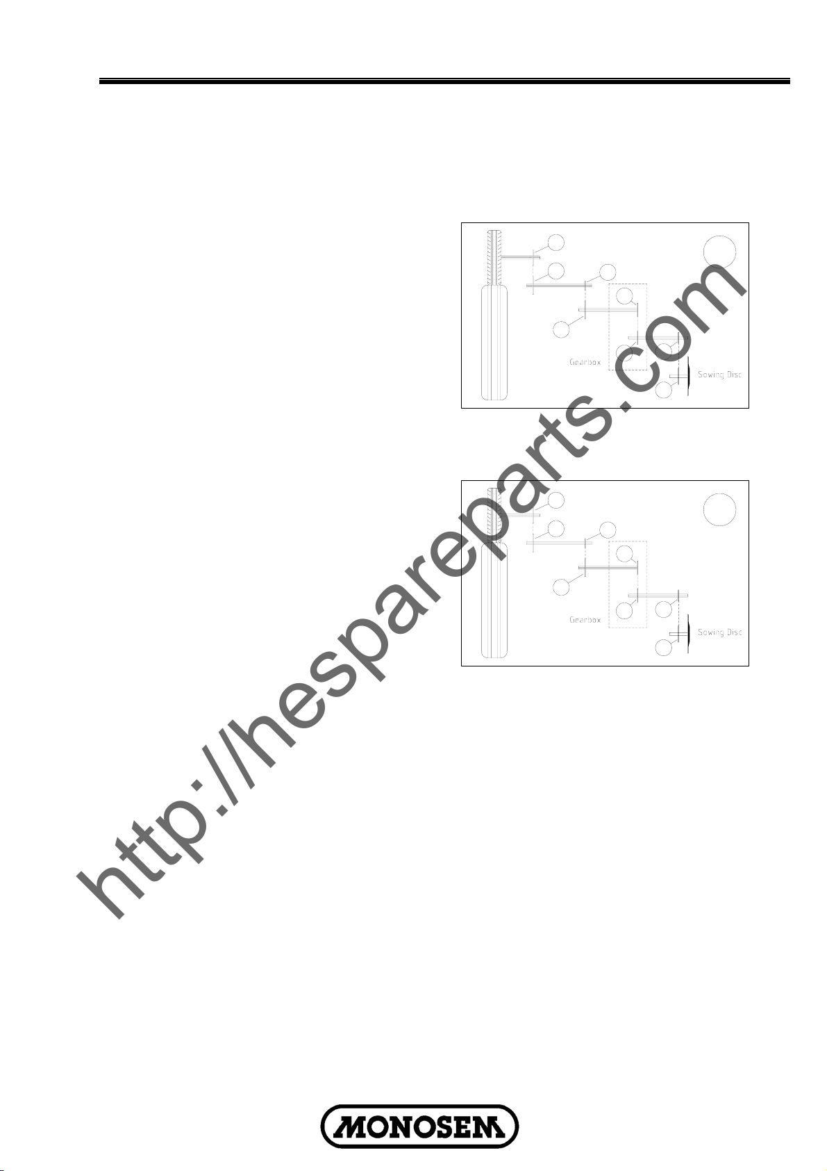
HYDRAULIC SYSTEM SCHEMATIC Planter Raising
HYDRAULIC SYSTEM SCHEMATIC Planter Lowering
35
Page 38

http://hespareparts.com
Page 39

http://hespareparts.com
SPARE PARTS
Page 40

EXTRA HIGHT OUTPUT TURBOFAN
http://hespareparts.com
38
FR
Page 41

EXTRA HIGHT OUTPUT TURBOFAN
http://hespareparts.com
PART NO. DESCRIPTION
4240 SUPPORT FRAME EXTRA HI-OUTPUT TURBOFAN
4241 TURBOFAN HOUSING DRIVE BELT SIDE
4242 TURBOFAN HOUSING MANIFOLD SIDE
4243 FRAME BAND, EXTRA HI-OUTPUT TURBOFAN
4244 TURBOFAN BLADE, EXTRA HI-OUTPUT TURBOFAN
4245 SUPPORT DISC, EXTRA HI-OUTPUT TURBOFAN
4246 SNAPRING
4247 BUSHING
4248 SPINDLE
4249 PULLEY BELT, 540 RPM
4249.1 PULLEY BELT, 1000 RPM
4250 COVER SHIELD
4251 BEARING, UPPER SPINDLE (62072RS)
4252 BEARING, UPPER SPINDLE (63072RS)
4404.A EXTRA HI-OUTPUT TURBOFAN SUPPORT BRACKET
4405.A SPINDLE WITH ADAPTOR
4407 BEARING 62 MM (62062RS)
4408 BEARING 72 MM (63062RS)
4409 SNAPRING (LARGE)
4411 BUSHING
4412.A PULLEY 500 RPM 11 ⅜” DIA.
4412.1A PULLEY 1000 RPM 5 ⅞” DIA.
4429.A OUTPUT SHIELD
4434.3 SAFETY SHIELD
4437 LOCK KEY 8X7X40
4439.A LOCK KEY 6X6
4440 BOLT TO ADJUST BELT TENSION
4450 MANIFOLD, 12 HOLE
4453 HOSE CLAMP
4454 VACUUM HOSE, SPECIFY LENGTH
9525 END CAP, SUPPORT FRAME
31X412 WASHER
31X413 WASHER
FR
39
Page 42

HYDRAULIC DRIVE
http://hespareparts.com
PART NO. QTY. DESCRIPTION
4988 2 PUSH PULL CMC ½
4989 1 MGCYL FITTING – ½ X FJ ⅞
4990 1 COUPLING SLEEVE
4991 2 BLOCK FOR STANDARD TURBOFAN
4992 1 HYDRAULIC MOTOR BRACKET
4994 1 HYDRAULIC MOTOR WITH VALVE 59 CC – FTA0027
4995 1 UNIDIRECTION CHOKE ½
4996 2 HOSE ½ LG.4 M
4997 2 UNION MSAE ¾ X MLIC ⅞
4998 1 UNION MGCYL ½ X MJ ⅞
4999 2 UNION UM 15L X ½ GCYL NU
5000 2 BUSHING BS ½
40
FR
Page 43

PLANTING UNIT – NG PLUS 2
http://hespareparts.com
FR
41
Page 44

PLANTING UNIT – NG PLUS 2
http://hespareparts.com
PART NO. DESCRIPTION
4502.S U BOLT, 7X7
5021 BUSHING (B25)
5681.B SCRAPER SPRING, TENSION
6090 SNAPRING 6 MM
6202 COLLAR BRACE FOR COVER
6463 PIN, 6 MM DIA. X 65 MM LENGTH
6779 BUSHING SELF-LUBRICATING
6795 WING NUT, 8 MM
6915 SNAPRING, 30 MM
6963 PIVOT PIN REAR, LOWER
PARALLEL LINKAGE
6965 PIVOT PIN FRONT, UPPER
PARALLEL LINKAGE
6967.7 CLAMP FACING, 7X7
6972.1 SAFETY CLUTCH
6998 SPRING
7012.DA REMOVAL RIGHT-HAND SPINDLE
7012.GA REMOVAL LEFT-HAND SPINDLE
7014.A BEARING
7048.A BUSHING, SHOULDERED
7049 SPRING
7064.C MAIN FRAME, NG PLUS 2
7065 INTERCHANGEABLE CAST POINT
7065.A V-SLICE INSERT
7065.S V SHOE INSERT, SMALL SEED
7067 SPACERS FOR UNIT LOCK UP
7068.CO OPENING DISC COMPLETE
7068 OPENING DISC Ø380 MM
7010.A DISC HUB, USES 6X22 RIVETS
7014.A DISC BEARING (3204-2RS)
7015.A WASHER (6204ID)
7069.A ADJUSTABLE BLOCK FOR DEPTH
CONTROL
7070 SWING BRACKET
7076 ROD FOR PRESSURE
ADJUSTMENT
7077.2 PLASTIC HOPPER, 60 L
7078 WIRESTOP DEPTH ROD
7079 BLANK TUBE
7079.2 STANDARD TUBE WITH SENSOR
7079.1 STANDARD TUBE ONLY
D1700270S1 STANDARD SENSOR ONLY
7079.2S STANDARD TUBE WITH SENSITIVE
SENSOR
7079.4 TUBE FOR SMALL SEED ONLY
D2440891S1 SENSITIVE SENSOR ONLY
7079.3S PEANUT TUBE WITH SENSOR
7079.3 PEANUT TUBE ONLY
D1700270S1 STANDARD SENSOR ONLY
7083 HANDWHEEL DEPTH CONTROL
7084.1 RIGHT OUTSIDE SCRAPER
7084.2 LEFT OUTSIDE SCRAPER
7085.DA INSECTICIDE DROP TUBE, RIGHT
7085.GA INSECTICIDE DROP TUBE, LEFT
7086 PIN SEED TUBE
7087.A PIN FOR ADJ. BLOCK DEPTH
CONTROL, USES TWO 5X40 SPLIT
PINS
7089 SMALL CHAIN SHIELD
7090.A CHAIN GUARD
7091 HAIR PIN
7094 BUSHING
7095 PIVOT PIN
7096 CHAIN ROLLER
7097 UPPER PARALLEL LINKAGE ARM
7098 LOWER PARALLEL LINKAGE ARM
7099 PIVOT PIN REAR, UPPER
7100 SELF-LUBRICATING BUSHING
7101 FRONT BRACE CLOD REMOVER
7102.A CLOD REMOVER BRACKET
PART NO. DESCRIPTION
7103.A CLOD REMOVER
7104.CO LID PLASTIC HOPPER, WITH
7104.2 SPRING CLIP
7105 SPACERS FOR UNIT
7106 METAL HANDLE FOR UNIT LOCK
7106.ASY HANDLE FOR UNIT LOCK UP
7107 PLASTIC HANDLE FOR UNIT LOCK
7108 BUSHING
7109 CHAIN TIGHTENER
7114 DRIVE CHAIN METERING UNIT
(124 LINKS)
7124 UNIT STOP
7125 SEED CHUTE
7127 THREADED ROD
7130.BASY UNIT LOCK UP ASSEMBLY
7130.A UNIT LOCK UP
7066 BUSHING
7136 SPRING
7262.A REAR SPACER
7269 INTERMEDIATE PRESS WHEEL, SS
7271 BRACKET, INTERMEDIATE PRESS
7272 BRACKET, SCRAPER PIVOTING
7273 BRACKET, SCRAPER MOUNTING
7274 SCRAPER GREENFLEX
7275 SHOULDERED BOLT, BRACKET
7276 LOCKUP STOP
7278 RETAINING RING, BEARING
11579 BEARING (30X55X13)
11580 SNAPRING (I55)
PARALLEL LINKAGE ARM
SPRING CLIP
UP
UP
W/HANDLE
WHEEL
PIVOTING
42
FR
Page 45

PLANTING UNIT – NG PLUS 2
http://hespareparts.com
HARDWARE :
F38664 HEX METRIC 10X70
F40166 HEX NUT, 10 MM
10170015 2,5X5 COTTER PIN
10502012 10X15 BOLT
10502016 10X25 BOLT
10511007 6X100 BOLT
10511064 8X70 BOLT
10512018 10X35 BOLT
10512019 10X40 BOLT
10512027 10X100 BOLT
10512029 10X120 BOLT
10512054 12X70 BOLT
10512059 12X120 BOLT
10530094 6X20 BOLT
10170065 5X30 COTTER PIN
10170067 5X40 COTTER PIN
10172090 6X25 ROLL PIN
10172091 6X30 ROLL PIN
10176004 6X22 RIVET
10620095 10X27X2 WASHER
10621026 13X18X2 (12X18X2) WASHER
10622024 16.5X26X1 (16X26X1) WASHER
10622026 16.5X20X2 (16X26X2) WASHER
10622052 17X50X1 (16X50X1) WASHER
20016010 7X41 WASHER
GAUGE WHEEL :
7072.DF GAUGE WHEEL ARM, RIGHTHAND
7072.GF GAUGE WHEEL ARM, LEFTHAND
7073.N NYLON GAUGE WHEEL
COMPLETE
7073.2 TIRE ONLY
7122.D GAUGE WHEEL SCRAPER,
RIGHT HAND
7122.G GAUGE WHEEL SCRAPER,
LEFT HAND
900125 BEARING, 40 MM
30513015 RIGHT-HAND 16X80 BOLT
30513115 LEFT-HAND 16X80 BOLT
ADJUSTABLE CLOSING WHEEL :
7071.A TENSION ROD
7074.NASY COMPLETE ADJ. CLOSING
WHEEL W/BRACKET
7074.N COMPLETE ADJ. CLOSING
WHEEL
7074.1B HALF ADJ. CLOSING WHEEL
7074.2 TIRE, CLOSING WHEEL, 1X12
7080.B BRACKET ADJ. CLOSING
WHEEL
7082 HANDWHEEL PRESSURE
CONTROL
7259 SPRING
7260 STOP WASHER
7261 NUT
F38709 12X45 BRACKET MOUNTING
BOLT
F40165 12 MM HEX NUT
F13005 HSC ¼ - 20X1Z5
10621046 13X27X2 WASHER
900125 BEARING, 40 MM
900159 BUSHING
30513015 RIGHT-HAND MOUNTING
BOLT
30513115 LEFT-HAND MOUNTING BOLT
FR
43
Page 46

METERING BOX – NG PLUS
http://hespareparts.com
44
FR
Page 47

METERING BOX – NG PLUS
http://hespareparts.com
PART NO. DESCRIPTION
4329.A SNAPRING
5692 WING NUT, 10 MM
6077 LYNCH PIN
6089 RUBBER RING
6090 SNAPRING 6 MM
6092 SPRING (R132)
6200.A HOUSING FOR METERING BOX
ONLY
6201 COVER
6202 COLLAR BRACE FOR COVER
6203.A PLASTIC INSERT
6204.A BRONZE INJECTOR BLOCK
ASSEMBLY WITH 6X10 SCREW
6205 CONTROL WINDOW
6206 TIGHTENING CAP
6207 SHAFT METERING BOX
6208 TIGHTENING ROD COVER
6209.A BRACE FOR PLASTIC INSERT
6210 PRESSURE PIN SCRAPER
6211 STANDARD SCRAPER
6211.2A SCRAPER USE WITH PEANUTS,
LARGE SEED
6212.A AGITATOR, BRASS (STANDARD)
6213 SNAPRING (E20)
6214 TRAP DOOR
6215 SPRING FOR TRAP DOOR
6216 FIXED PIN SCRAPER
6217 ADJUSTABLE PIN SCRAPER
6218 PRESSURE SPRING
6219 PIN CONTROL WINDOW
6221 BEARING
6222 HARDWARE FOR 6212.A
AGITATOR
6225 CASING FOR EJECTOR BLOCK
SPRING
6227 SPRING, SELECTOR HANDLE
6228 SELECTOR HANDLE
6230.A REMOVABLE PLUG
6232 GASKET INSIDE METERING BOX
COVER
6233 GATE INSIDE METERING BOX
COVER
6233.1 SPECIAL PLATE FOR SMALL
SEED
6235 COMPLETE COVER, STANDARD
6235.M PEANUT COVER, COMPLETE
6238 EJECTOR, PEANUT
7110 SPROCKETS, 27 TOOTH
7115 SPROCKET, 26 TOOTH
7117 DUAL SPROCKET, 26-12 TOOTH
9999.NG METERING BOX COMPLETE, NG
9999.NG+ METERING BOX COMPLETE,
NG+
10072094 SCREW, FOR METERING BOX
BRACE, 6209.A
10530060 SCREW, PHILLIPS HEAD, 5X10
10172043 ROLL PIN, 4X35
10172099 ROLL PIN, 6X70
10173022 ROLL PIN, 8X50
Standard seed discs, complete with agitator :
DC0325 3 hole, 2.5 mm, melons, low population
DC3x2x2.5 3 hole, 2.5 mm, melons, double seed drop
DC0335 3 hole, 3.5 mm, pumpkin, low population
DC0625 6 hole, 2.5 mm, melons, medium population
DC0635 6 hole, 3.5 mm, pumpkin, low population
DC0925 9 hole, 2.5 mm, melons, high population
DC0930D 9 hole, 3.0 mm, hilldrop cotton, double seed
drop
DC0930T 9 hole, 3.0 mm, hilldrop cotton, triple seed drop
DC0935 9 hole, 3.5 mm, pumpkin, high population
DC1225 12 hole, 2.5 mm, sunflower, low population (oils
& confection)
DC1230D 12 hole, 3.0 mm, hilldrop cotton, double seed
drop
DC1230T 12 hole, 3.0 mm, hilldrop cotton, triple seed
drop
DC1820 18 hole, 2.0 mm, cucumber, hand harvest
DC1825 18 hole, 2.5 mm, sunflower, high population
(oils & confection)
DC1850 18 hole, 5.0 mm, corn, low population
DC2437 24 hole, 3.7 mm, sweetcorn, small seed
DC2445 24 hole, 4.5 mm, sweetcorn, large seed
DC2450 24 hole, 5.0 mm, corn, medium population
DC3016 30 hole, 1.6 mm, sugarbeets, small-medium
DC3020 30 hole, 2.0 mm, pickles, machine harvest
DC3050 30 hole, 5.0 mm, corn, high population
DC3065 30 hole, 6.5 mm, kidney beans, large peanuts
DC3610 36 hole, 1.0 mm, onion, low population
DC3612 36 hole, 1.2 mm,
cabbage/cauliflower/pepper/tomato, low
population
DC3622 36 hole, 2.2 mm, sorghum, low population
DC3635 36 hole, 3.5 mm, cotton, low population
DC3660 36 hole, 6.0 mm, peanut/beans, large
DC3665 36 hole, 6.5 mm, peanut (large, jumbo)
Beans (large kidney)
DC4016 40 hole, 1.6 mm, sugarbeets, small, medium,
large
DC4020 40 hole, 2.0 mm, sugarbeets, medium, large
pellets
DC4060 40 hole, 6.0 mm, peanut, small to medium
DC4850 48 hole, 5.0 mm, beans, large (pinto)
DC6035 60 hole, 3.5 mm, beans, small (navy)
DC6045 60 hole, 4.5 mm, beans medium, (snap) &
soybeans (pinto)
DC7210 72 hole, 1.0 mm, onion, high population
DC7212 72 hole, 1.2 mm,
cabbage/cauliflower/pepper/tomato, high population
DC7222 72 hole, 2.2 mm, sorghum, high population
DC7235 72 hole, 3.5 mm, cotton, high population
DN….. Seed disc only (stainless portion with holes)
less agitator, order seed disc number preceded by DN
FR
45
Page 48

MICROSEM
http://hespareparts.com
46
FR
Page 49

MICROSEM
http://hespareparts.com
PART NO. DESCRIPTION
4329.A SNAPRING
4478 V BOLT Ø16, 7 X 7
4821 PART FOR HYDRAULIC TUBE HOLDING
5021 BUSHING (B25)
5516 HAIR PIN
6090 SNAPRING, 6MM
7085.DA INSECTICIDE DROP TUBE, RIGHT
7085.GA INSECTICIDE DROP TUBE, LEFT
7088 HOPPER LID, 25 LT.
7088.2 CLIP FOR HOPPER LID
7108 SPACER BUSHING
7109 NG PLUS UNIT IDLER
7158 MICROSEM DRIVE CHAIN 7X7, LOWER 70
LINKS
9158 SPRING (R57)
9174 TENSION SPRING
9280 BUSHING
9500.A LEFT & RIGHT SIDE HOUSING
9502.1A HELICID HOPPER
9502.C MICROSEM HOPPER
9504 STEEL BASE, HOPPER
9505.A RUBBER FLAP
9506 MAIN SPINDLE
9507 LEFT WORM GEAR (V75G)
9508 RIGHT WORM GEAR (F75G)
9509 CENTRAL GEAR
9512 TRAP DOOR
9513.B SEAL TRAP DOOR
9514 LEVER STOPPER
9516 SPRING (R139)
9517 BOLT (A117)
9518 PART FOR MICROSEM HOSE HOLDING
9519 UNIT CAP
9520 DOUBLE OUTLET, INSECTICIDE
9520.A DOUBLE OUTLET, HERBICIDE
9521 PLUG
9522 MICROSEM HOSE, SPECIFY LENGTH
9523 CLAMP
9525 END CAP
9548.D SUPPORT BAR, 7 X 7 STD
9549 CARRIER BAR, SPECIFY LENGTH
9552 BUSHING, USES 2 4X25RP AND 2 6X30RP
9553.B MICROSEM DRIVE CHAIN 7X7, UPPER 110
LINKS
9554.3 12 TOOTH SPROCKET
9554.6 15 TOOTH SPROCKET
9554.9 18 TOOTH SPROCKET
9554.13 22 TOOTH SPROCKET
9554.16 25 TOOTH SPROCKET
9554.21 30 TOOTH SPROCKET
9555.A SPROCKET 12-25 TOOTH
9557 SMALL LYNCH PIN
9559 BUSHING
9562 ROLLER FOR CHAIN TIGHTNER
9565 RUBBER O RING
9568 MICROSEM HOSE CLAMP
9574 PLATE FOR HOPPER, 1 OUTLET
9606.A UPPER DRIVE SPROCKET, 20 TOOTH
9612 INTERMEDIATE SPINDLE
9613 SPRING CHAIN TIGHTNER
9638.A ADJUSTABLE MICRO BRACKET DOUBLE
PILLOW BLOCK
9645 RUBBER SLEEVE
9650.2T INTERIOR MICROSEM ROD, 2 HOLES
9651.2T EXTERIOR MICROSEM ROD, 2
HOLES
9653 CHAIN TIGHTNER
9654 DBLE INTERMEDIATE SPROCKET
9656.1 REINFORCEMENT PLATE, 7X7 STD
9658 ROLLER SPACER TUBE
9661 FEMALE SHOE DROP TUBE
9662 MALE SLIDING TUBE
9720 SUPPORT BRACKET, 7X7 STD
9721 OPENING SAFETY SHIELD, DRIVE
CHAIN
9723 CLOSING PIN, SAFETY SHIELD
9724.1 CLOSING CLIPS
9726 SNAP RING
10118 GREASER
FR
47
Page 50

FERTILIZER
http://hespareparts.com
48
FR
Page 51

FERTILIZER
http://hespareparts.com
PART NO. DESCRIPTION
4329.A SNAPRING
4478 V CLAMP Ø16
4479 U CLAMP Ø16
4515 BEARING
4523 BUSHING STOP
4786.C 7X7 GEARBOX IDLER (96)
4787 7X7 WHEEL UNIT IDLER HANDLE
4827 CHAIN IDLER ROLLER
4841 BALANCING SPRING
5021 BUSHING (B25)
7009 DISK ONLY
7010.A DISK HUB
7012.DA REMOVABLE RH SPINDLE
7012.GA REMOVABLE LH SPINDLE
7014.A DISK BEARING (32042RS, 52042RS)
7015.A WASHER (6204ID)
7016.D SCRAPER, INSIDE RIGHT
7016.G SCRAPER, INSIDE LEFT
7017.B BRACKET SCRAPERS
7018.A SCARPER, OUTSIDE
7158 LATERAL CHAIN ON NG
METERING UNIT
9159.A FERTILIZER HOSE COMPLETE 24"
9171.B SPROCKET CLUSTER, FERTILIZER
DRIVE
9173 BEARING HOLDER
9242 FERTILIZER DISK BRACKET
SLEEVE TUBE
9244 SPRING BUSHING
9246.2 ARTICULATION TUBE
9247.D RIGHT FERTILIZER DISK BRACKET
9247.G LEFT FERTILIZER DISK BRACKET
9248 FERTILIZER DISK ARM
9249 FERTLIZER DEPTH CONTROL
THREADRED ROD
9250 FERTILIZER FIXING SHAFT
9251 FERTILIZER FIXING FORK
9252 FERTILIZER DEPTH CONTROL
ARTIC. SHAFT
9253.D FERTILIZER BRACKET FORK
9254.2A PLASTIC FERTILIZER HOPPER, 2
OUTLET
9255 ALUMINIUM HOUSING
9256 SPRING, TRAP DOOR
9257.2 METAL LID FOR HOPPER, 2
OUTLET
9258 FERTILIZER HOSE CLAMP
9261 INSIDE HOPPER REINFORCEMENT
9262.1A STANDARD FERTILIZER AUGER
9263.1 TRAP DOOR, 1 OUTLET
9264.B SPINDLE FOR FERTILIZER
METERING UNIT 95
9265.C INSIDE CAP FOR FERTILIZER 93
9266.A DRIVE SHAFT BETWEEN HOPPERS,
FOR 4-ROW
9267 PIN FOR TRAP DOOR
9268 REINFORCEMENT BRACKET
9269.2A FERTILIZER SLEVE FOR 2 OUTLET
HOPPER
9279 DRIVE FORK
9280 BUSHING
9281 FERTILIZER DISK OFF-SET
9282 FERTILIZER DISK OFF-SET CLAMP
9288 FERTILIZER HOPPER SUPPORT
9289.2 SUPPORT BAR FERTILIZER 2
OUTLET HOPPER
9290 FERTILIZER DRIVE BRACKET
9292 FERTILIZER BRACKET SIMPLE
FOOT
9293 FERTILIZER BRACKET COMBINED
FOOT
9525 END CAP MICROSEM BAR
9549 MICROSEM BRACKET BAR
9555.A SPROCKET, 12-25 TOOTH
9557 SMALL LYNCH PIN
9565 O RING
9613 SPRING CHAIN TIGHTNER (R81)
9650.052 INTERIOR DRIVE CONNECTOR
ROD, 52 CM
9651.035 EXTERIOR DRIVE CONNECTOR
ROD, 31,5 CM
10118 GREASER
FR
49
Page 52

PVC PIPE AND HOSE ASSEMBLY
http://hespareparts.com
50
US
Page 53

FRAME ASSEMBLY
http://hespareparts.com
US
51
Page 54

FRAME ASSEMBLY
http://hespareparts.com
ITEM PART NO. QTY. DESCRIPTION
1. 1-298-010001-1 10 FITTING, GREASE ¼-28
2. 1-512-010005-01 2 NUT, HEX 1/4-20 GRB
3. 1-512010007-16 2 NUT, HEX 1-1/4-7 GRB
4. 1-654-010047-04 2 SCREW, HEX HEAD CAP ¼-20 X ¾ GR5
5. 1-654-010059-03 2 SCREW, HEX HEAD CAP ⅝ -11 X 1- ½ GR5
6. 1-861-010032-29 4 WASHER, FLAT 1- ¼ W
7. 1-861-010034-15 2 WASHER, SPLIT LOCK ⅝
8. 101406 3 PIN, COTTER ⅜ X 3
9. 104033 12 PIN, COTTER 5/32 X 1-½
10. 116076 2 SPRING LEVELING ARM WELDMENT
11. 116237 1 TURNBUCKLE, CONNECTOR WING TO MAIN FRAME
12. 116238 1 HOOK WELDMENT
13. 116248 10 BUSHING, MACHINERY, 10GA
14. 116260 1 CENTER SPRING WELDMENT
15. 116051 3 EYEBOLT
16. 116358 1 PIN, 2-⅛ X 20
17. 116359 4 PIN, ⅞ X 3-⅛
18. 116363 2 PIN, ⅞ X 6-9/16
19. 116365 2 WING HINGE WELDMENT
20. 116241 1 MAIN FRAME WELDMENT, RH (1230 REAR VAC)
21. 116212 1 MAIN FRAME WELDMENT, LH (1230 REAR VAC)
22. 116186 1 WING WELDMENT, RH (1230 REAR VAC)
23. 116187 1 WING WELDMENT, LH (1230 REAR VAC)
24. 116367 2 RUBBER SPACER, WING HINGE, MAIN FRAME
25. 103817 2 HOSE CLAMP
26. 1-512-01005-05 2 NUT, HEX LOCK ⅜
27. 100825 2 WASHER, SLOTTED LOCK 1-¼
28. 1-512-010005-03 8 NUT, HEX LOCK 5/16 - 18
29. 1-557-010362-63 REF PIN, COTTER ¼ X 2
30. 1-654-010049-07 8 SCREW, HEX HEAD CAP 5/16 -18 X 1- ½ GR5
31 1-654-010051-09 REF SCREW, HEX HEAD CAP ⅜ -16 X 2 GR5
32 1-654-010125-10 2 SCREW, HEX HEAD CAP ⅛ X 3- ¼
33 1-861-010032-09 16 WASHER, FLAT 5/16
34 -1861-010032-09 2 WASHER, SPLIT LOCK 1"
35 70260977 1 SMV EMBLEM
36 116034 REF PIN, DBL HOLE ROW MARKER PIVOT
37 116070 2 ROW MARKER PIVOT WELDMENT
38 116514 1 DECAL, WARNING MONOSEM
39 1-512-010005-13 REF NUT, HEX LOCK ⅝ -11
40 112120 REF SCREW, HEX HEAD CAP ⅝ -11 X 2-1/4 GR8
41 116100 REF WASHER, FLAT 1 – ¼ N
42 1-512-010005-15 4 NUT, HEX LOCK ¾ -10
43 1-654-010061-05 2 SCREW, HEX HEAD CAP ¾ -10 X 2 GR5
52
US
Page 55

HYDRAULIC WING FOLD ASSEMBLY
http://hespareparts.com
ITEM PART NO. QTY. DESCRIPTION
1
2
3
4
5
6
7
8
9
10
11
12
13
14
15
16
17
18
19
20
21
1/4 X 1-1/2 24 PIN, COTTER 1/4 X 1-1/2
116037 2 BAR, WING HINGE, PIVOT
116256 2 ARM WELDMENT, WING HINGE
116258 4 SPACER WING HINGE
116341 2 CYLINDER BASE, 3 X 16
116429 2 HOSE ASSEMBLY 3/8 X 25
116440 2 PIN, 1 X 7-3/16
116441 2 PIN, 1 X 5-3/4
116442 4 PIN, 1 X 3-1/8
118-2680-010 4 CONNECTOR
2062-8-6S 4 ELBOW 90
620-0859 4 ADAPTER
1-512-010007-05 4 NUT, HEX 1/4-20
1-654-010047-06 2 SREW, HEX HEAD CAP 1/4-20 X 1
1-654-010047-14 2 SREW, HEX HEAD CAP 1/4-20 X 3
1-681-010034-09 4 WASHER, SPLIT LOCK 1/4
116259 1 ANGLE W/ HOLES
102-1123 2 SWIVEL (12/16 ROW REAR & TOP VAC)
HOSE ASSEMBLY 3/8 X 158 (16 ROW REAR & TOP
116430 2
112158 2
116350 1 VALVE ASSEMBLY
VAC)
HOSE ASSEMBLY 3/8 X 136 (16 ROW REAR & TOP
VAC)
US
53
Page 56

HICTH ASSEMBLY
http://hespareparts.com
ITEM PART NO. QTY. DESCRIPTION
1
2
3
4
5
6
7
8
9
10
11
12
13
14
15
16
17
18
19
20
21
22
1-298-010001-1 3 ZERK, FITTING 1/4
1-512-010005-01 1 NUT, HEX LOCK 1/4-20
1-512-010005-05 3 NUT, HEX LOCK 3/8-16
1-512-010005-13 3 NUT, HEX LOCK 5/8-11 GRB
1-512-010005-15 2 NUT, HEX LOCK 3/4-10 GRB
1-512-010005-19 3 NUT, HEX LOCK 1-8 GRB
1-512-010007-06 2 NUT, HEX LOCK 5/16-18
1-512-010007-11 2 NUT, HEX LOCK 5/8-11 GRB
1-512-010007-12 12 NUT, HEX 3/4-10 GRB
1-512-010008-12 1 NUT, HEX 3/4-16 GRB
1-654-010049-05 2 SCREW, HEX HEAD CAP 5/16-18 X 1 GR5
1-654-010051-05 2 SCREW, HEX HEAD CAP 3/8-16 X 1 GR5
1-654-010059-13 1 SCREW, HEX HEAD CAP 5/8-11 X 4 GR5
1-654-010059-16 2 SCREW, HEX HEAD CAP 5/8-11 X 5-1/2 GR5
1-654-010061-09 14 SCREW, HEX HEAD CAP 3/4-10 X 3 GR5
1-654-010087-16 1 SCREW, HEX HEAD CAP 3/4-16 X 5-1/2 GR8
1-654-010125-20 2 SCREW, HEX HEAD CAP 1-8 X 7-1/2 GR8
1-861-010032-07 1 WASHER, FLAT 1/4W
1-861-010032-11 2 WASHER, FLAT 3/8W
1-861-010032-19 2 WASHER, FLAT 5/8W
1-861-010032-21 1 WASHER, FLAT 3/4W
1-861-010034-10 2 WASHER, SPLIT LOCK 5/16
54
US
Page 57

HICTH ASSEMBLY
http://hespareparts.com
ITEM PART NO. QTY. DESCRIPTION
23
24
25
26
27
28
29
30
117402 1 HITCH TUBE WELDMENT RH W/O TURBO
31
32
33
34
35
36
37
38
39
40
41
42
43
44
45
46
47
1-861-010034-15 2 WASHER, SPLIT LOCK 5/8
1-861-010034-17 12 WASHER, SPLIT LOCK 3/4
1A63478 1 JACK 7000 LB.
100214 1 HITCH, CLEVIS PPI-208V
100676 1 BUSHING 1.06 X 0.79 X 0.62
116036 1 BRACKET, HITCH
116093 1 HITCH TUBE WELDMENT LH
116106 1 HITCH TUBE WELDMENT RH
(1230/1630 REAR & TOP VAC)
MNT
(1228 TOP VAC & 2422 REAR & TOP VAC)
116113 1 PIN WELDMENT PULL HITCH
116183 1 HITCH CAP WELDMENT
116184 2 SLEEVE, 3-3/16
116185 2 SLEEVE, 3-1/8
116196 1 WRENCH WELDMENT
116211 1 TUBE, SPACER SAFETY CHAIN
116248 2 BUSHING, MACHINERY 10GA
116250 2 PIN, 5/8 W/L
116407 1 BUSHING, HITCH MIDDLE HINGE
116445 1 HOSE HOLDER
116715 1 SCREW, HEX HEAD CAP 5/8-11 X 6-1/2 GR8
2-181-010001 6 HOSE CLAMP
2-375-010601 1 HITCH, RING CAT III
70239854 1 PIN, QUICK HITCH
70328064 1 BLOCK, SPACING
70594087 1 CHAIN ASSEMBLY, SAFETY TOW 10,500#
709273326 1 WASHER, PLATE .78 X 1.75 X 7 GA
55
US
Page 58

ROW MARKER ASSEMBLY
http://hespareparts.com
ITEM PART NO. QTY. DESCRIPTION
1
2
3
4
5
6
8
9
10
12
14
56
1-298-010001-1 6 FITTING, GREASE 1/4-28
1-511-010001-07 2 NUT, HEX JAM 5/8-11
1-512-010005-05 4 NUT, HEX LOCK 3/8-16
1-512-010005-13 4 NUT, HEX LOCK 5/8-11
1-512-010007-07 4 NUT, HEX 3/8-16
1-512-010007-09 4 NUT, HEX 1/2-13
1-557-010362-63 12 PIN, COTTER 1/4 X 2
1-654-010051-07 2 SCREW, HEX HEAD CAP 3/8-16 X 1-1/2 GR5
1-654-010051-08 4 SCREW, HEX HEAD CAP 3/8-16 X 1-3/4 GR5
1-654-010051-11 2 SCREW, HEX HEAD CAP 3/8-16 X 2-1/2 GR5
1-654-010059-11 2 SCREW, HEX HEAD CAP 5/8-11 X 3-1/2 GR5
US
Page 59

ROW MARKER ASSEMBLY
http://hespareparts.com
ITEM PART NO. QTY. DESCRIPTION
15
16
17
18
19
20
21
22
23
24
25
26
27
28
29
30
31
32
33
34
35
36
37
38
39
40
41
41
1-861-010032-11 4 WASHER, FLAT 3/8W
1-861-010034-11 6 WASHER, SPLIT LOCK 3/8
1-861-010034-13 4 WASHER, SPLIT LOCK 1/2
1-861-010034-15 8 WASHER, SPLIT LOCK 5/8
119084 4 PIN, COTTER 1/4 X 1-1/2
112120 12 SCREW, HEX HEAD CAP 5/8-11 X 2-1/4 GR8
116029 2 ROW MARKER LINKAGE WELDMEBT
116032 4 PIN, WASHER ROW MARKER WLDMT
116034 2 PIN, DOUBLE HOLE ROW MARKER PIVOT
116035 2 EXTENSION TUBE/R/MKR ASSEMBLY
116454 2 ROW MARKER OUTER ASSEMBLY (16 ROW)
116070 REF ROW MARKER PIVOT ASSEMBLY
116100 12 WASHER, FLAT 1-1/4N
116176 2 ROW MARKER FIRST ARM WELDMENT
ROW MARKER MID ARM WELDMENT (16
116452 2
116339 2 YOKE EXTERNAL THREADED PLAIN
116344 2 CYLINDER, MARKER 2-1/2 X 20
116354 2 TUBE 5/8 X 1-7/8
116355 2 PIN 7/8 X 11
116366 2
116405 2 YOKE, INTERNAL THREADED CLEVIS
116438 2 PIN, 1-1/4 X 12-1/4
120369 2 CHAIN, ROW MARKER (16 ROW)
120400 2 CHAIN COVER ROW MARKER (16 ROW)
2-181-010001 2 HOSE CLAMP
8-102-010019 2 U-BOLT SCRAPPER
116446 LH SPINDLE & HUB WELDMENT
116447 RH SPINDLE & HUB WELDMENT
116337 BLADE SOLID, 16" PLAIN
ROW)
RUBBER SPACER ROW MARKER OUTER
ARM
57
US
Page 60

MARKER SUPPORT ASSEMBLY
http://hespareparts.com
ITEM PART NO. QTY. DESCRIPTION
1 1-512-010007-06 8 NUT, HEX 5/16 - 18
2 1-512-010007-09 8 NUT, HEX ½ - 13
3 1-512-010007-11 8 NUT, HEX ⅝ - 11
4 1-861-010034-10 8 WASHER, SPLIT LOCK 5/16
7 104031 4 SCREW, RD HEAD SQ NECK 5/16 – 18 x 1 GR5
8 104906 4 SCREW, RD HEAD SQ NECK 5/16 – 18 x 3 GR5
9 117184 2 PLATE, MARKER BRACE (16 ROW)
10 117186 2 RUBBER ARMORITE
11 117185 2 BRACE ASSEMBLY (16 ROW)
12 70593063 4 U BOLT
13 8-102-010019 4 U BOLT SCRAPER (16 ROW)
58
US
Page 61

MARKER SPINDLE / HUB / BLADE ASSEMBLY
http://hespareparts.com
ITEM PART NO. DESCRIPTION
1
2
3
4
5
6
7
8
9
10
11
12
13
14
15
16
17
18
19
20
21
22
1-512-010005-03 NUT, HEX LOCK 5/16-18
1-512-010007-09 NUT, HEX 1/2-13
SCREW, HEX HEAD CAP 5/16-18 X 1
1-654-010049-05
1-654-010070-11
1-861-010034-13 WASHER, SPLIT LOCK 1/2
116038
116254 WASHER MARKER MOUNT
116337 BLADE, SOLID 16" PLAIN
116390 DEPTH BAND WELDMENT
116446
116447
830025 SCREW, HEX HEAD CAP 1/2-20 X 1
125612 HUB CAP 1517 (P502013)
125616 NUT, HEX SLOTTED 5/8-18 (P251701)
125615 PIN, COTTER 5/32 X 1-1/2 (P401905)
125617 WASHER, FLAT 5/8 (P301801)
70336915 OUTER CONE LM11749 (P752231)
125614
70336914 OUTER CUP LM11710 (P702218)
70336916 INNER CUP L44610 (P702215)
125613 INNER CONE (P752316)
125611 GREASE SEAL CR12411 (P602123)
GR5
SCREW, RD HEAD SQ. NECK 1/2-13 X
3-1/2
SHIPPING RETAINER, ROW MARKER
HUB
LH SPINDLE AND HUB WELDMENT
(ITEMS 13-22)
RH SPINDLE AND HUB WELDMENT
(ITEMS 13-22)
HUB W/ CUPS (084000-4) (INCL.
ITEMS 19-20)
US
59
Page 62

LIFT WHEEL ASSEMBLY
http://hespareparts.com
60
US
Page 63

DRIVE WHEEL ASSEMBLY
http://hespareparts.com
US
61
Page 64

LIFT AND DRIVE WHEEL ASSEMBLY
http://hespareparts.com
ITEM PART NO. DESCRIPTION
1
2
3
4
5
6
7
8
9
10
11
12
13
14
15
16
17
18
19
20
21
22
23
24
25
26
27
28
29
30
31
32
33
34
35
36
37
38
39
40
41
42
43
44
45
46
47
48
49
1-298-010001-1 FITTING, GREASE 1/4-28
1-511-010001-05 NUT, HEX JAM 1/2-13
70917835 NUT, HEX THIN LOCK NYLONJAM 1/2-13
1-512-010002-14 NUT, HEX LOCK 5/8-18
1-512-010005-03 NUT, HEX LOCK 5/16-18 GRB
1-512-010005-05 NUT, HEX LOCK 3/8-16 GRB
1-512-010005-09 NUT, HEX LOCK 1/2-13 GRB
1-512-010005-13 NUT, HEX LOCK 5/8-11 GRB
1-512-010007-09 NUT, HEX 1/2-13 GRB
1-512-010007-11 NUT, HEX 5/8-11 GRB
1-512-010007-12 NUT, HEX 3/4-10 GRB
1-557-010362-63 PIN, COTTER 1/4 X 2
1-647-010004217 PIN, SLOTTED SPRING 1/4 X 1-1/2
1-647-010004255 PIN, SLOTTED SPRING 3/8 X 2
1-654-010051-05 SCREW, HEX HEAD CAP 3/8-16 X 1 GR5
1-654-010051-06 SCREW, HEX HEAD CAP 3/8-16 X 1 GR5
1-654-010055-05 SCREW, HEX HEAD CAP 1/2-13 X 2 GR5
1-654-010055-07 SCREW, HEX HEAD CAP 1/2-13 X 2-1/2 GR5
1-654-010059-02 SCREW, HEX HEAD CAP 5/8-11 X 2 GR5
1-654-010059-05 SCREW, HEX HEAD CAP 5/8-11 X 2 GR5
1-654-010059-07 SCREW, HEX HEAD CAP 5/8-11 X 2-1/2 GR5
1-654-010059-11 SCREW, HEX HEAD CAP 5/8-11 X 3-1/2 GR5
1-654-010061-03 SCREW, HEX HEAD CAP 3/4-10 X 1-1/2 GR5
1-654-010061-05 SCREW, HEX HEAD CAP 3/4-10 X 2 GR5
1-654-010070-03 SCREW, RD HEAD SQ NECK 1/2-13 X 1-1/2
1-654-010090-04 SCREW, HEX HEAD CAP 5/8-18 X 1-3/4 GR8
1-861-010032-09 WASHER, FLAT 5/16W
1-861-010032-14 WASHER, FLAT 1/2N
1-861-010032-15 WASHER, FLAT 1/2W
1-861-010034-17 WASHER, SPLIT LOCK 3/4
100827 NUT, FLANGE HD SERR. 5/8-11
104031 SCREW, RD HEAD SQ NECK 5/16-18 X 1 GR5
116044 BAR TENSIONER MOUNT
116068 SCRAPER
116079 DRIVE WHEEL ASSEMBLY
116086 SCRAPER MOUNT WELDMENT
116100 WASHER, FLAT 1-1/4N
166235 SPACER
116249 PIN, CLEVIS 5/16 X 1
116336 RING RETAINING EXT 5/16
116368 IDLER ARM WELDMENT
116401 ADJUSTABLE DRIVE MOUNT
116439 TUBE
116620 CONTACT DRIVE WHEEL AND HUB ASSEMBLY - 8 INCH
116716 SCREW, HEX FULL THREAD 1/2-13 X 4
117414 SPRING CHAIN TIGHTENER
117957 MACHINERY BUSHING
122831 SPROCKET, TRANSMISSION 30 TEETH W/ CLUTCH
122835 SPROCKET, TRANSMISSION 15 TEETH
62
US
Page 65

LIFT AND DRIVE WHEEL ASSEMBLY
http://hespareparts.com
ITEM PART NO. DESCRIPTION
50
51
52
53
54
55
56
57
58
59
60
61
62
63
64
65
66
67
68
69
70
71
72
73
74
75
76
78
79
80
122836 SPROCKET, TRANSMISSION 30 TEETH
122838 SPROCKET, TRANSMISSION 23 TEETH
122840 SHAFT, HEX 7/8 X 12-3/4
122841 SHAFT, HEX 7/8 X 11-5/8
122846 HANGER BEARING, 7/8 HEX SHAFT
122847 BEARING MOUNT TRIANGULAR
122848 BEARING SELF ALIGNING 7/8 HEX SHAFT
122871 SPROCKET, TRANSMISSION 18 TEETH IDLER
2-720-010034 SPRING, EXT SPRAY SHIELD
7/8MACH BUSH BUSHING MACHINERY 7/8
71503635 COLLAR RETAINING 1"
116018 DRIVE WHEEL CLAMP ASSEMBLY, TOP
116023 DRIVE WHEEL ARM ASSEMBLY
116041 RETAINING PIN WELDMENT
116090 WHEEL TOWER ASSEMBLY
116346 RIM 5-1/2 X 20
116348 VALVE STEM
116353 TIRE 7-1/2 X 20
116356 PIN, 1-1/4 X 12
116360 PIN, 1-1/4 X 5-5/8
116406 SPINDLE TRANSPORT AND GROUND WHEEL
116569 SNAP RING
123879 HUB ASSEMBLY (INCL. ITEMS 73-76)
125626 HUB W/ CUPS (INCL. ITEM 75)
125627 BEARING CONE 13600LA
125628 BEARING CUP 13621
125629 WHEEL BOLT 9/16-18 X 1-1/8
116087 LOCK-UP WELDMENT
116251 PIN, DETENT 1/2 X 4-1/2
116065 LOCK-UP MOUNT
63
US
Page 66

TRANSMISSION ASSEMBLY
http://hespareparts.com
64
US
Page 67

TRANSMISSION ASSEMBLY
http://hespareparts.com
ITEM PART NO. QTY DESCRIPTION
1
2
3
4
5
6
7
8
9
10
11
12
13
14
15
16
17
18
19
20
21
22
23
24
25
26
27
28
29
30
31
32
33
34
35
36
37
38
1-298-010001-1 2 ZERK FITTING 1/4
1-512-010005-03 24 NUT, HEX LOCK 5/16-18 GRB
1-557-010327 6 PIN, LYNCH 1/4 X 1-1/4
1-557-010362-51 4 PIN, COTTER 3/16 X 1-1/2
1-557-010362-54 2 PIN, COTTER 3/16 X 2-1/4
1-557-010362-63 4 PIN, COTTER 1/4 X 2
1-647-010004217 8 SPRING PIN, SLOTTED 1/4 X 1-1/2
1-861-010032-09 18 WASHER, FLAT 5/16W
1-861-010032-18 4 WASHER, FLAT 5/8N
104031 24 SCREW, RD HEAD SQ NECK 5/16-18 X GR5
117957 8 MACHINERY BUSHING
117974 2 TRANSMISSION WELDMENT
118657 4 BUSHING, MACH 5/8 X 1
122847 16 BEARING MOUNT, TRIANGULAR
122848 8 BEARING, SELF ALIGN HEX SHAFT 7/8
122853 4 COUPLER, DRIVE SHAFT
122865 2 SHAFT, UPPER 7/8 HEX
124971 4 NUT, HEX FLANGE SPIRALOCK 1/2-13
125706 4 IDLER, CHAIN #50
125711 2 SPROCKET, STORAGE WELDMENT
125784 2 SPROCKET, TRANSMISSION 15 TEETH
125713 2 SPROCKET, TRANSMISSION 17 TEETH
125715 2 SPROCKET, TRANSMISSION 19 TEETH
125716 2 SPROCKET, TRANSMISSION 21 TEETH
125717 2 SPROCKET, TRANSMISSION 23 TEETH
125718 2 SPROCKET, TRANSMISSION 24 TEETH
125719 2 SPROCKET, TRANSMISSION 25 TEETH
125720 2 SPROCKET, TRANSMISSION 30 TEETH
125780 2 SPROCKET, TRANSMISSION 27 TEETH
125783 2 SPROCKET, TRANSMISSION 28 TEETH
125793 2 HANDLE WELDMENT, CHAIN TIGHTENER
125934 2 PLATE WELDMENT, CHAIN TIGHTENER
125935 2 SPRING, CHAIN TIGHTENER
125948 2 COUPLER SHEAR
125949 2 SHAFT, TRANSMISSION
125953 2 PIN, LOCK CHAIN TIGHTENER
125954 2 SPRING , COMPRESSION
126354 2 PLATE, TRANSMISSION
126368 4 SCREW, HEX HEAD CAP 1/2-13 X 9-1/2
70918196 4 PIN, QUICK .094 X 1.625
US
65
Page 68

HEX SHAFT COUPLER
http://hespareparts.com
ITEM PART DESCRIPTION
3. Spring pin, ¼” x 1 - ½”
16. 4967 Machine bushing, 1” x 1 – ½” x ⅛”
31. 4969 Spring
32. Hex head cap screw ¼-20 x 2-¼”
¼-20 Nylock
33. 4986 Coupler
34. 4968 Bushing ½"
66
FR
Page 69

HYDRAULIC ASSEMBLY
http://hespareparts.com
US
67
Page 70

HYDRAULIC ASSEMBLY
http://hespareparts.com
ITEM PART NO. QTY. DESCRIPTION
1 1-512-010005-05 1 NUT, HEX LOCK ⅜ - 16
2 1-654-010051-06 1 SCREW, HEX HEAD CAP ⅜ - 16 x 1 – ¼ GR5
3 1-861-010032-11 2 WASHER, FLAT ⅜ W
4 1-861-010032-20 2 WASHER, FLAT ¾ N
5 102-1095 12 ADAPTER STRAIGHT
6 102-1170 2 FITTING, TEE
7 105874 16 TIE, STRAP PLASTIC (NOT SHOWN)
8 116428 4 HOSE ASSEMBLY ⅜ x 173
9 116431 4 HOSE ASSEMBLY ⅜ x 15
10 116434 4 HOSE ASSEMBLY ⅜ x 120
11 116489 2 HOSE ASSEMBLY ⅜ x 64
12 116490 2 HOSE ASSEMBLY ⅜ x 78
13 116492 2 HOSE ASSEMBLY ⅜ x 128
14 116497 1 VIBRATION STRAP
15 117161 2 HOSE ASSEMBLY ⅜ x 312
16 117162 2 HOSE ASSEMBLY ⅜ x 324
17 117163 2 HOSE ASSEMBLY ⅜ x 196
18 2062-8-8S 4 ADAPTER, 90
19 2071-8-8S 4 ADAPTER, 90
20 3-299-010016 4 TEE
21 8010-4 4 COUPLER, MALE ½
22 1-654-010051-05 2 SCREW, HEX HEAD CAP ⅜ - 16 x 1 GR5
23 1-861-010034-11 2 WASHER, SPLIT LOCK ⅜
24 116349 1 VALVE ASSEMBLY
25 116340 REF CYLINDER, ASSIST LIFT 3 – ¼ x 8
26 116342 REF CYLINDER, SLAVE LIFT 3 – ¼ x 8
27 116343 REF CYLINDER, MASTER LIFT 3 – ½ x 8
28 116344 REF CYLINDER, MARKER 2 – ½ x 20
30 BC-0868 REF CYLINDER, SLAVE 3 x 8 REPHASE
68
US
Page 71

3 - ¼ x 8 LIFT ASSIST CYLINDER ASSEMBLY
http://hespareparts.com
ITEM PART NO. QTY. DESCRIPTION
116340 Cylinder, Hydraulic lift assist 3- ¼ x 8
1 117515 1 Piston rod assembly
2 1 Butt & tube assembly
3 117519 1 Piston
4 117520 1 Gland
5 125564 1 Spacer
6 220000209 1 Locknut
7 200300040 2 Shipping plug
8 125565 1 Grease zerk
9 125566 1 Du-bushing
117522 Packing kit (Incl. All o-ring and seals)
US
69
Page 72

3 x 16 WING FOLD CYLINDER ASSEMBLY
http://hespareparts.com
ITEM PART NO. QTY DESIGNATION
116341 Cylinder, Hydraulic wing fold 3 x 16
1 117523 1 Piston rod assembly
2 1 Butt & tube assembly
3 117524 1 Piston
4 117525 1 Gland
5 220000209 1 Locknut
6 200300040 2 Shipping plug
7 100000423 1 Clevis assembly
8 190400108 2 Clevis pin
9 111789 4 Roll pin
117526 Packing kit (Incl. All o-ring and seals)
70
US
Page 73

3 - ¼ x 8 SLAVE LIFT CYLINDER ASSEMBLY
http://hespareparts.com
ITEM PART NO. QTY DESIGNATION
116342 Cylinder, Hydraulic slave lift 3- ¼ x 8
1 117515 1 Piston rod assembly
2 1 Butt & tube assembly
3 117519 1 Piston
4 117520 1 Gland
5 220000209 1 Locknut
6 200300040 2 Shipping plug
7 125565 1 Grease zerk
8 125566 1 Du-bushing
9 125567 1 Relief valve
10 125568 1 Washer
117521 Packing kit (Incl. All o-ring and seals)
US
71
Page 74

3 – ½ x 8 MASTER LIFT CYLINDER ASSEMBLY
http://hespareparts.com
ITEM PART NO. QTY DESIGNATION
116343 Cylinder, Hydraulic master lift 3- ¼ x 8
1 117515 1 Piston rod assembly
2 1 Butt & tube assembly
3 117516 1 Piston
4 117517 1 Gland
5 220000209 1 Locknut
6 200300040 2 Shipping plug
7 125565 1 Grease zerk
8 125566 1 Du-bushing
9 125567 1 Relief valve
10 125568 1 Washer
117518 Packing kit (Incl. All o-ring and seals)
72
US
Page 75

http://hespareparts.com
ITEM PART NO. QTY DESIGNATION
116344 Cylinder, Hydraulic marker 2- ½ x 20
1 120802 1 Piston rod assembly
2 1 Butt & tube assembly
3 117512 1 Piston
4 120803 1 Gland
5 220000208 1 Locknut
6 200300040 2 Shipping plug
7 125563 1 SQ. Wire tape
117514 Packing kit (Incl. All o-ring and seals)
Page 76

http://hespareparts.com
COMPAGNIE COMMERCIALE RIBOULEAU
Immeuble Permaphone
76, avenue des Champs Elysées – 75008 PARIS
Usine – Technique – Recherche – Informations
12, rue de l’industrie – 79240 LARGEASSE France
TEL. 05 49 81 50 00 – FAX 05 49 72 09 70 – http://www.monosem.com
 Loading...