


TABLE OF CONTENTS
OPERATOR’S MANUAL
DM-4600
Monosem, Inc.
1001 Blake St.
Edwardsville, KS 66111
(913) 438-1700
www.monosem-inc.com

OPERATOR’S MANUAL
NOTES:
2
DM-4600

OPERATOR’S MANUAL
Table of Contents
System Overview .......................................................................................................................... 4
Specifications ............................................................................................................................ 5
Installation ........................................................................................................................... 6-7
Quick Start ................................................................................................................................ 8-13
Implement Setup....................................................................................................................... 8
Sensor Setup ........................................................................................................................... 8-9
Target Rates ............................................................................................................................. 10
Accessories and Options .................................................................................................. 11-12
Speed Setup ....................................................................................................................... 12-13
Monitor Operations ..................................................................................................................... 14
Home Screen ...................................................................................................................... 14-15
Dash View ........................................................................................................................... 16-17
Singulation Screen .................................................................................................................. 18
MPH Indicator .......................................................................................................................... 19
Internal GPS Status .................................................................................................................. 20
Lift Switch Configuration / Hopper Type Sensor Setup ...................................................... 21
VAC/Pressure Sensor Setup .............................................................................................. 22-23
Flow meter installation .......................................................................................................... 24-27
Master Flow Sensor.................................................................................................................. 28
Post Season Storage ............................................................................................................... 29
Harness Pinouts ...................................................................................................................... 30-32
Parts and Accessories ........................................................................................................... 33-34
Warranty ....................................................................................................................................... 36
3
DM-4600

OPERATOR’S MANUAL
INTRODUCTION
System Overview
The DM-4600 Planter Monitor is designed for maximum performance in the field and is
easy to install and use. The system is capable of monitoring up to 32 rows and provides
not only seed population, but also will display area, and has capabilities of monitoring
liquid flow with Monosem “Visu-Flo Technology”.
7” Color Touch Screen
DM-4600 1-32 Row Monitoring
Built in GPS Speed option
Bar graphs
Setup assist for easy programming
Adjustable accumulating time
RAM 1 1/2” Ball Mount
Adjustable Back light
Day/Night Mode
Adjustable Audible Alarm
Optional Visual Alarm Light
View Home or Dashboard
View Seed population or GPM
View 20 sec. Row History
Visu-Flo Option
Optional Lift Switch
2 Hopper Level, 2 RPM, 2 Vac. Opt.
Section grouping
4
DM-4600
SPECIFICATIONS
Power
10–16 VDC, 3.5 A maximum
Operating
-20°C to 70°C (-4°F to 158°F)
Storage temperature
-40°C to 85°C (-40°F to 185°F)
Size
24.1 cm W x 18 cm H x 6.8 cm D (9.5"
W x 7" H x 2.7" D)
Weight
3.58 kg (7.9 lb) for 32-row DM-4600 system
Wire Harnesses
The DM-4600 includes detachable
harnesses to supply the unit's power
(fused) and sensor inputs (to hitch).
Connectors on the back for GPS
Antenna, USB and Radar (4 pin)
Sensors
Compatible with Monosem and other
major brands of seed sensors.
Standard mounting
RAM Mount 1
½
” Ball Mounting
Alarm adjustment
Four levels audible alarm with mute
onscreen selection. Optional external light
available.
Backlight adjustment
Five increments plus Day/Night mode
OPERATOR’S MANUAL
SAFETY NOTICES
5
DM-4600
OPERATOR’S MANUAL
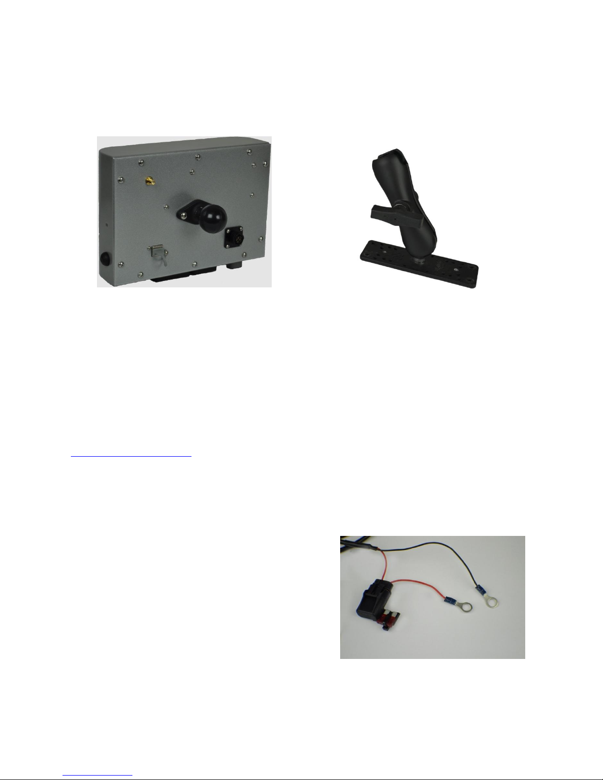
Optional RAM Base Mount
Part Number: 301108
INSTALLATION
Your DM-4600 comes with a RAM 1 ½” Mounting Ball. Any RAM Mount 1 ½” fixtures will
adapt to your monitor.
Install the RAM-238-U 1 ½” Ball supplied with your console by removing the two screws
from the rear of the unit and use them to attach the ball.
Any RAM configuration may be used to attach your console to a convenient location in
your cab. If you need a base mount, see the above for the optional 301108 base. See
your local dealer for brackets and arms that are available, or visit
www.agdirectusa.com to purchase online.
MONITOR AND POWER CONNECTIONS (Harness 301104)
Route the power leads of the main harness to the battery. Allow some slack to tie the
harness off to a secure location in the cab to provide strain relief and for the protection
of the harness.
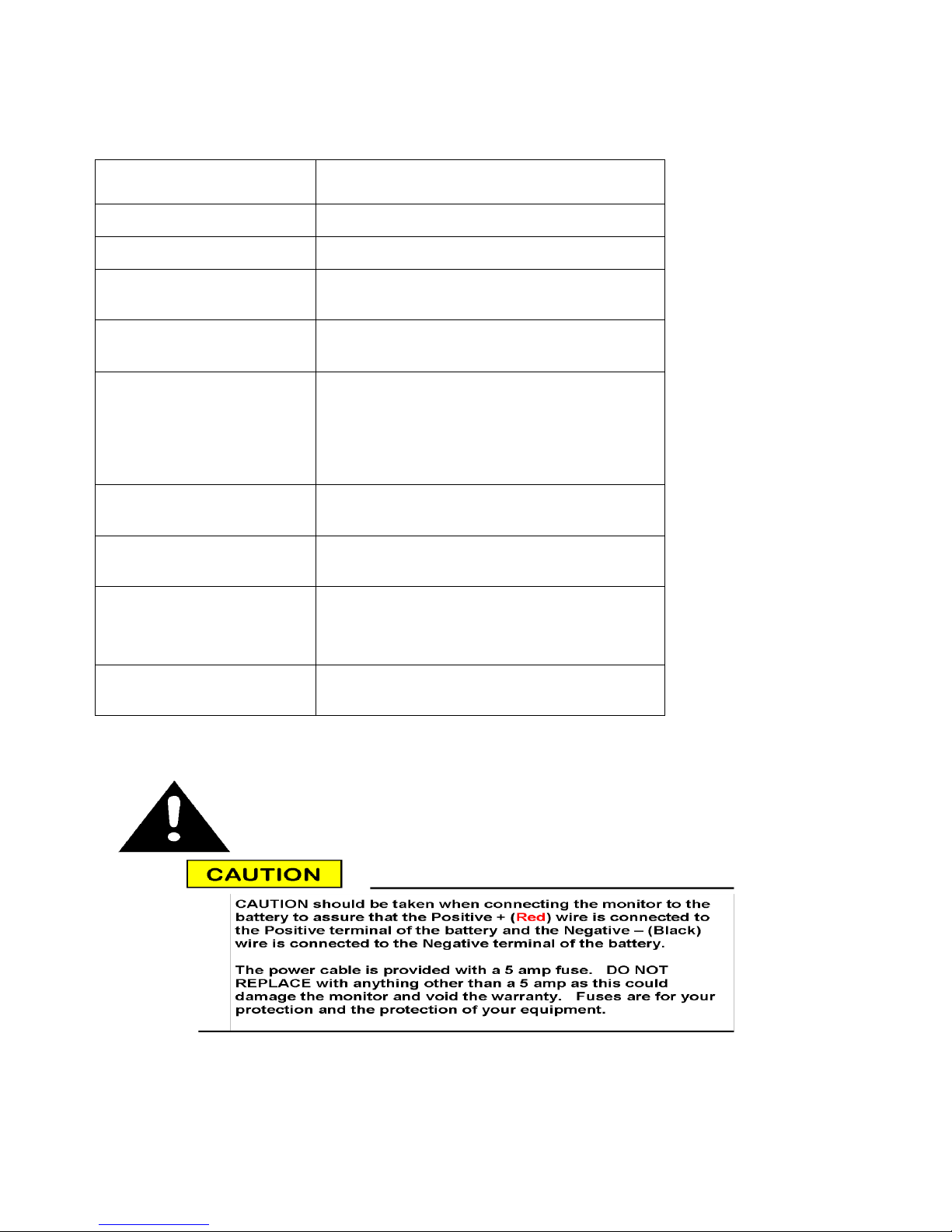
The monitor operates on 12 VDC only. The red
(Fused) lead should be connected to the
positive battery terminal and the black lead
should be connected to the negative battery
terminal.
There is a short two pin Deutsch connector at the monitor end of the power cord. This
is for connecting the optional Visual Alarm Light (Part No. 301109)
6
DM-4600

OPERATOR’S MANUAL
DM-4600 CONSOLE MAIN HARNESS (Harness 301106)
Route the main harness to the rear of the tractor. Attach the connector to the bottom
of the monitor with a ¼” nut driver. Tie the harness securely in the cab as a strain relief.
The 301106 harness will attach to your planter with a 37 pin AMP CPC style connector.
This connector is pinned to match standards used by Monosem.
If you are using an external speed source such as a radar or external GPS, connect it to
the 4 pin AMP connector on the back of the monitor. (Adapters are available for most
common radar and GPS connectors)
If you are using the internal GPS, attach the antenna to the coax connector on the
back of the monitor.
Once your implement is connected, you are ready to operate your monitor.
INTERNAL GPS
The DM-4600 comes with the onboard GPS enabled.
7
DM-4600
OPERATOR’S MANUAL
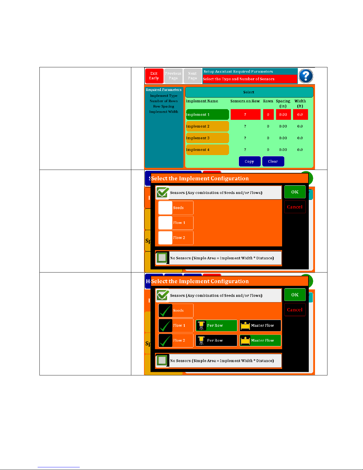
The first screen on an
original startup will take
you directly to the Setup
Assistant screen shown at
right. You will find a list of
required parameters on
the left and red boxes that
need to be filled in on the
right.
Touch the Sensors on Row
box and this pop up
screen will appear.
Choose from any
combination of Seed or
Flow inputs. Select No
Sensors if only using the
monitor for an acre
counter.
Selecting Flow 1 or Flow 2
will offer an additional
option of individual row
flow meters or a single
master flow meter. After
the desired configuration
is set, touch “OK” in top
right of pop up screen.
(Ref Master flow meter set
up on pg. 28)
QUICK START
Turn monitor on by depressing the On/Off Switch on the right end panel.
DM-4600
8
OPERATOR’S MANUAL
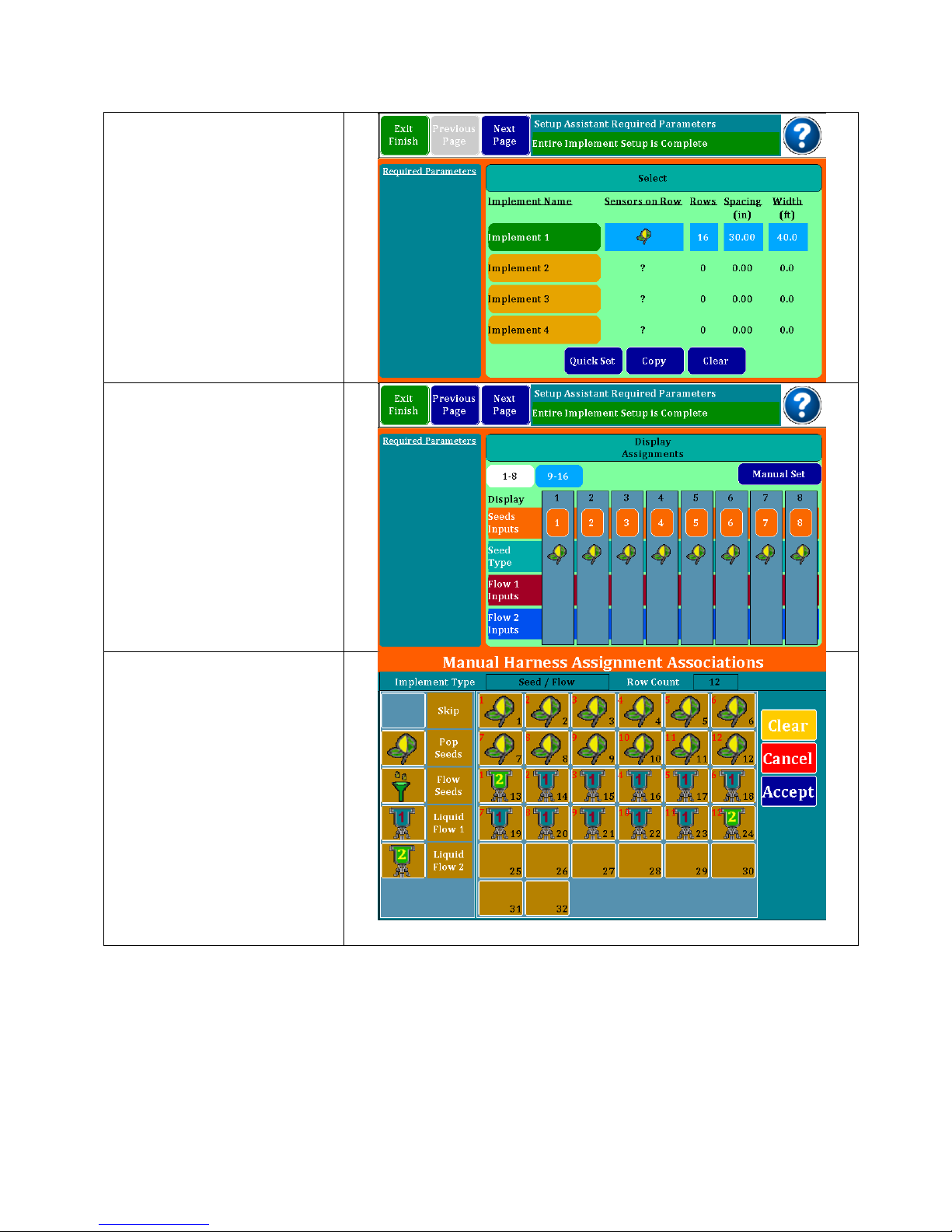
Continue by entering the
number of rows, row
spacing and implement
width. The Implement
Name may be
personalized using the
pop-up keyboard.
Select the Next Page to
continue to Sensor
Configuration.
From the display
assignments screen, you
can change types of
sensors manually or
configure skip row setups.
To open a configuration
box, touch on one of the
rows in this screen. This will
bring up the planter matrix
where changes can be
entered.
Touch any of the vertical
bars in the above screen
to bring up the manual
assignment screen. Here
you can touch an input
and change sensors or
skip rows. Screen at right
shows a 12 row seed
monitor with 12 flow
meters and two different
flow rates. The funnel is for
flow blockage sensors
often used on air seeders.
9
DM-4600
OPERATOR’S MANUAL
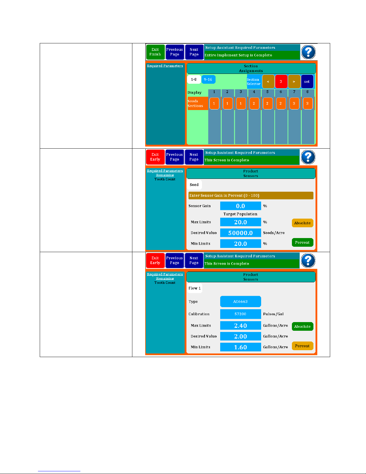
Section assignments may
be entered in this screen.
If you have a planter or
liquid system that is setup
with section shutoff’s, you
can configure the rows to
match so the monitor will
recognize the shutoffs and
not report continuous row
failures. Select section
number at top, then touch
the row pad to add it to
that section.
The product sensors screen
is where target rates are
entered and limits are
assigned. For seeds, set
the desired value and
default is +/- 20%. You
may change percentages
or enter absolute numbers.
If one or more flow inputs
are selected, you must
select the flowmeter part
number (found on your
flowmeters) and then
enter the desired GPA
along with the limits. The
calibration number is auto
generated. If you have
two flow inputs, you will
scroll to flow 2 setup where
you will repeat the above
steps.
DM-4600
10
OPERATOR’S MANUAL
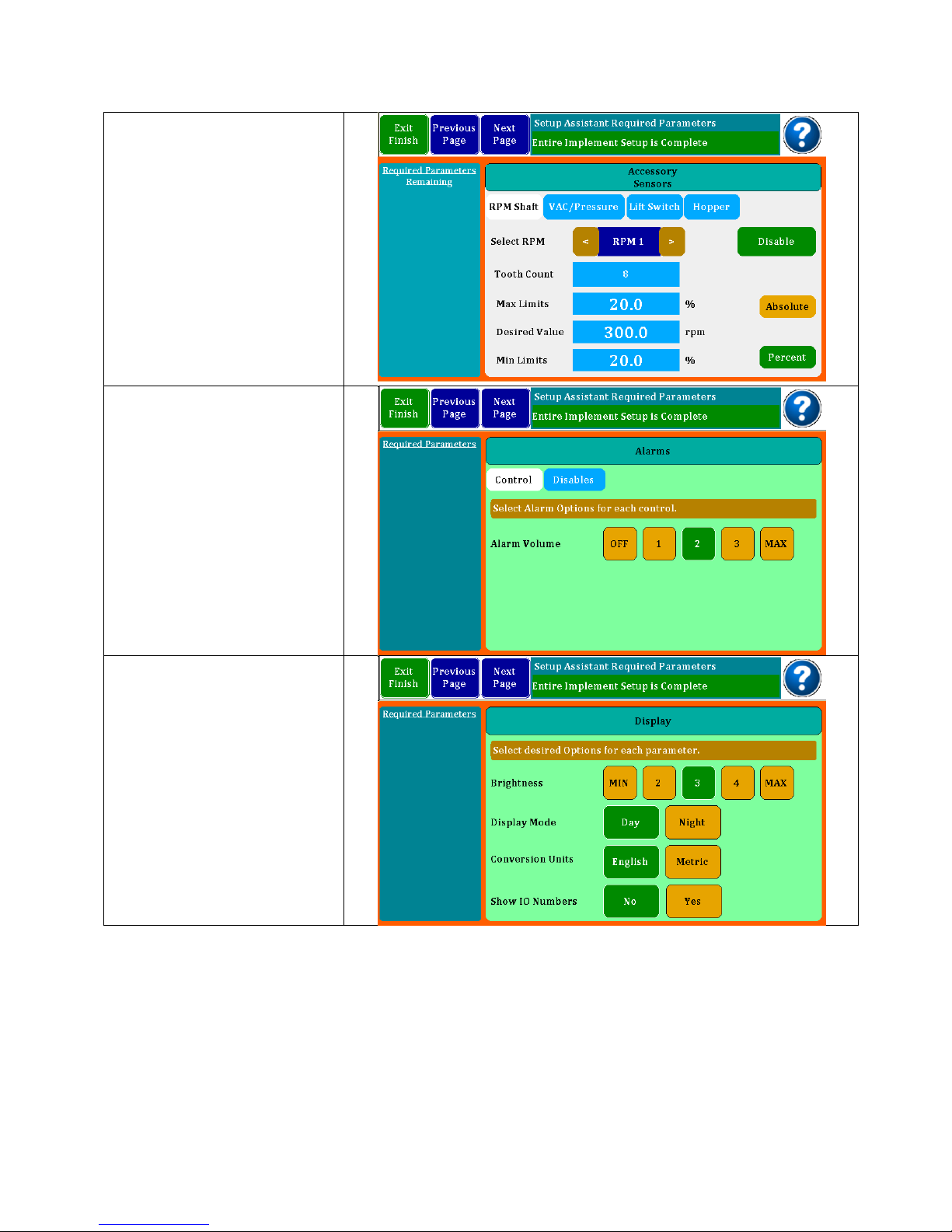
If you have RPM,
VAC/Pressure, Lift Switch
or Hopper Level sensors,
you will need to scroll to
those setups where you
will enter the required
information similar to what
you have done in seed
and flow sensor setup.
(Ref Accessory Sensor set
up on pg.21 and pg.22)
Alarm setup screens are
next. With the first one you
set the volume followed
by a screen where alarms
for accessory sensors may
be disabled or enabled.
The Display setup is where
the screen brightness and
Day/Night Mode are set.
Conversion units may be
set to English or Metric.
Show IO Numbers when
enabled will show the
actual input pin number
on the bar graph row
indicators. This is normally
set to No.
11
DM-4600

OPERATOR’S MANUAL
Sensitivity is the amount of
averaging time used to
calculate rates. The
longer times may show
more accuracy, but
changes will come less
often. This is normally set to
Low or Medium.
The Speed Input screen is
where you select what will
be your primary source of
speed. You can select
Manual where you enter a
number for the speed you
are driving; Radar is used
when an external Radar or
GPS device is plugged into
the 4 pin port on the back
of the monitor. The third
choice is the Internal GPS
when enabled. Speed
Input Alarms may be set
for over speed.
When using an external
Radar or GPS, you will
need to calibrate the
device. This is done by
driving a 400 foot course.
It is suggested that you do
4 runs and the monitor will
store and average them
for you. Flag your course
and as you pass the first
flag, press Start.
DM-4600
12

OPERATOR’S MANUAL
When you pass the
second flag, press End. A
calibration number will
appear in the Run # box.
Continue to do three more
runs to get an accurate
number. The monitor will
average the numbers and
press Save to keep the
calibration number.
Speed derived by this
calibration will be quite
accurate.
Exit the Setup Assistant
and go to the Home
screen. This brings up the
Bar Graph Screen. The
Bar Graph Screen will give
you a visual indication of
each row and showing
over or under rates
compared to average.
There is an information
screen that will show MinMax-Ave as well as other
information
Speed/Area Mode
provides a very simple
screen that calculates the
acres covered. Selection
and Configuration of this
mode is very similar to
selection and
configuration of other
Seed/Flow implements. In
the Setup Screen select an
Implement then press on
the associated Sensors on
Row Icon area. This will
bring up the new “Select
the Implement
Configuration” dialog box.
In this dialog select the
check box at the bottom,
the check box text is “No
Sensors”.
After selecting an Implement with No Sensors, the Setup
screens will be reduced to other setup requirements. You
may navigate to the Area/Speed screen by pressing the
Home Button at the top of the Monitor. In the Area/Speed
screen you will get a count of Acres. This count can be
Started or Stopped with the Enable/Disable buttons. You
may also reset the Acre count at any time.
13
DM-4600

OPERATOR’S MANUAL
By selecting Seeds, Flow 1 or Flow
2, you bring up a menu box shown
at the right end of the screen.
Shown at right are the three types
of screens you may see for any
product.
The first selection gives the option
of selecting a row and parking on
it. The second shows Min-Max-Avg
for the product and the last shows
a 20 second moving line graph
history of a selected row.
OPERATING YOUR MONITOR
Once your monitor is configured, you may choose to work from one of the screens on
the previous page.
Getting around the Home Screen….
The three buttons at the top left select the screen. Here we are looking at the Home or
Bar Graph Screen. Seeds and Flow bring up the appropriate Dash View while Setup
takes you back to the setup mode. Speed is displayed to the right and the indicator
showing the type of speed input is displayed. Above figure showing Radar or External
GPS input.
Next, you will find the Information Box and the View Selection buttons. Shown above is
a monitor set for Seed and Flow with two rates. The Avg. View button is selected
showing the Average of each of the applications, Seeds, Flow 1 and Flow 2.
DM-4600
14

OPERATOR’S MANUAL
Alarm indicator
The bar graphs will change color when the limits are exceeded either over or under as
shown below.
Limits exceeded:
The alarm may be temporarily silenced by holding down the individual row until it
changes color. The small alarm bell will have a circle/red X over it showing that the row
has been silenced. It may be returned to normal operation by holding the row down
again.
THE DASH SCREEN - SEEDS
The Seeds Dash Screen gives a quick overview of the operation. Shown at left is
Population in Seeds/Acre with the Average, the Minimum (Row Number) and Maximum
(Row Number).
15
DM-4600

OPERATOR’S MANUAL
Next is Spacing in inches with Average, Minimum (Row Number) and Maximum (Row
Number).
Across the top you will find the acre counters. There are three acre counter memories
in the system and they may be started, stopped or reset by holding the button down for
three seconds to bring up a Start/Stop and Reset button.
On the center right is the Acre/Hr. reading and the Singulation screen showing skips and
multiples.
The Seed Dash Board now allows the user to configure the 3 tiles on the bottom right as
RPM, Vacuum, Pressure or toggling Vac/Pressure. Simply press on the Tiles and a dialog
box will appear with possible Tile assignments.
With the VAC and Pressure capabilities, Tiles are available on the Seed and Flow
Dashboards. Tile Assignments will be saved for future power up cycles. All configurable
Tiles in the Dash boards are now identified with a small peel flip icon in the lower right
corner of the Tile.
16
DM-4600

THE DASH SCREEN – FLOW
OPERATOR’S MANUAL
The Flow Dash Screen is similar to the seeds screen. Shown at left is the Flow Rate. It will
Show GPA Average, Minimum (Row Number) and Maximum (Row Number). If you
have two Flows selected, there will be a second column for Flow 2.
Across the top you will find the acre counters. There are three acre counter memories
in the system and they may be started, stopped or reset by holding the button down for
three seconds to bring up a Start/Stop and Reset button. Shown above, a triangle
shows acres counting, whereas a square indicates counter has stopped.
Center right shows Acre/Hour rate followed by a calculated Field Flow 1 and Total Flow
1. Both of these may be started/stopped or cleared by holding the button down for
three seconds.
On the bottom row you will see the current average GPM flow rate (This will toggle
between Flow 1 and Flow 2 if you have both) and finally, you have Field Flow 2 and
Total Flow 2 which may be started/stopped or cleared by holding the button down for
three seconds.
The center lower 2 tiles can be configured with existing Acres/Hr, Flow GPM and the
new Pressure or Vac sensor values. Simply press on the Tiles and a dialog box will
appear with possible Tile Assignments.
17
DM-4600

OPERATOR’S MANUAL
THE SINGULATION SCREEN
The Singulation Screen provides row by row Singulation conditions. To enter this screen
navigate to the Seed Dashboard and press on the Singulation cell, you will be taken to
the Row Singulation screen.
After entering the screen you will have a view very similar to the Home Screen. The
screen has a console or statistics area, a view select area and a graphical area. The
view select area lets you chose from 3 different console statistics, Row Select, Max
Value, and Overall average. The Row Select shows the Singulation, Skips and Double of
the selected row, these values represent a percentage singulation. Press on the Row
Graphical area to select which Row to view. The Max Value shows the Row number
and Max value in percent of Skips and Multiples. The Row count value is a count of all
rows that are exhibiting Skips and Multiples. The Overall Average view contains the
values normal scene on the Seed Dashboard screen.
For each row graphical object you can see the present Skips and Multiple percentages.
Skips are shown in yellow above the center line and Multiples are shown in Red below
the center line. If neither of these colors show for a given Row this would indicate 100 %
singulation.
18
DM-4600

OPERATOR’S MANUAL
Shown at right are the three Speed
Input icons along with the MPH
Reading. At the top, the icon shows
Radar or external GPS Speed input
hooked to the 4 pin connector on the
rear of the monitor.
If you have internal GPS enabled, you
will see the second bar graph screen
showing lock and signal strength.
The final screen is manual speed
where you enter a speed by
incrementing with the gold boxes.
To toggle from one input to another,
hold down the icon for 2-3 seconds
and a dialog box will appear.
The screen shot above shows 12.2% Skips on Row 1 as shown in yellow. The Multiples are
at 24.5 and are shown in Red.
MPH INDICATOR
In the upper right of the Home Screen, you will find an indicator showing the MPH input
and a speed reading. By holding down this section of the screen for a few seconds,
you can bring up a dialog box to change input icons.
INTERNAL GPS STATUS
19
DM-4600

OPERATOR’S MANUAL
Zero Satellites
7 to 9 Satellites
1 to 3 Satellites
10 or more Satellites
4 to 6 Satellites
The far right indicator is blank or clear which means the GPS does not
have a lock on any satellites.
In this condition the GPS cannot determine the location, therefore Speed
cannot be determined.
The far right indicator is blue which means the GPS has a Lock on the
satellites.
In this condition the GPS can determine the location, and therefore
Speed can be determined.
The far right indicator is red which means the GPS has a WAAS Lock on
the satellites.
In this condition the GPS can determine the location, and therefore
Speed can be determined. The WAAS lock provides the GPS solution with
the highest accuracy.
The Internal GPS status is provided in the ICON located in the upper right corner of the
monitor display. This upper right corner area is described more fully in the MPH
INDICATOR section of the DM-4600 Operators Manual on page 15.
The GPS ICON indicates the Signal Strength and GPS Lock Status. The ICON is made up
of 5 bars, the left 4 bars indicate the Signal Strength and the tall bar on the far right
indicates the GPS Lock Status.
The Signal Strength is a measure of how many Satellites are being tracked by the GPS
sensor. The following table explains the 5 possible Signal Strength conditions:
The GPS Lock status is indicated by the color of the far right status bar. This status is truly
independent of the other 4 Satellite Strength status bars, however there is a correlation
between them. To establish a GPS lock the GPS sensor must be tracking several
satellites, to establish a GPS WAAS lock the GPS sensor typically requires even more
satellites. The following table provides the GPS Lock Status indicators with typical
Satellite Strengths:
DM-4600
20

OPERATOR’S MANUAL
LIFT SWITCH CONFIGURATION
The Lift switch may now be configured to be Normally Open or Normally Closed to
accommodate different lift switches
HOPPER TYPE SENSOR SETUP
Hopper Type to Setup/Implement/Sensor/Hopper screen, allowing user to select Active
Low or Active High Hopper Sensors.
21
DM-4600

OPERATOR’S MANUAL
VAC/PRESSURE SENSOR SETUP
VAC/Pressure setup, you may setup 2 sensors as either VAC or Pressure sensors.
Depending on your selection the setup screen will modify itself to ask for associated
information.
To select the desired Sensor type Press on the Sensor Selection button. This button will
provide a selection dialog box as follows. The list includes Off, Raven – Pressure, Dickey
John – Pressure, Dickey John – Vacuum and John Deere – Vacuum.
22
DM-4600

OPERATOR’S MANUAL
The Raven- Pressure Sensor requires a calibration. You may press the “Calibrate” purple
button to calibration your sensor. When you do this the following screen will provide
you with more steps.
If you Press the “Calibrate Now” button the system will show the following screen while it
performs the Calibrate function.
23
DM-4600

OPERATOR’S MANUAL
FLOW METER INSTALLATION
A plumbing diagram for a typical system used on a planter for the pop up/side by side
fertilizer has been included. Starting with the product tank that is normally mounted on
the planter frame each of the components used in the system will be discussed
regarding their function and installation.
#1 Leading out of the tank a main shutoff valve should be in place to cut product flow
to the entire system.
#2 The next component on the diagram is a filter which is critical for keeping foreign
material out of the pumping system that would cause plugs or blockages to occur. It is
recommended for an application rate of 5 gallons per acre or less to use an 80 mesh
filter screen. Application rates higher than 5 gallons per acre can be applied with a 50
mesh screen filter. A finer screen is used at lower application rates to keep the small
flow meters from plugging. The filter should be placed before the pump to allow for
proper filtering of the fertilizer being applied.
#3 The pump is the next item in line after the filter. There are many types of pumps that
are commonly used for liquid fertilizer application. Piston, squeeze, hydraulic and 12V
DC type pumps have all been used with this system. All these pumps work well as long
as they are properly sized for the specific application rate that is being applied.
#4 After the pump a cleanout port is shown that would be used for rinsing out the
system after the season is over. It may also be used for rinsing if you are going to be out
of the field and will not be using the system for an extended period of time. The
cleanout port will also be useful in flushing out the system if blockages should occur due
to contamination problems in the fertilizer system. The clean out port consists of a valve
and a garden hose adapter for hooking up the rinsing system.
#5 Following the cleanout port is the distribution manifold followed by the individual row
flow meters. The flow meters can be grouped together after the manifold or distributed
on the bar individually closer to each opener.
#6 An optional bracket (Part No. 6675) is available for purchase that holds up to 8 flow
meters. This will help keep track of which flow meter is going to which row plus it helps in
making a neat, safe, and organized installation of the flow meters. Each precision flow
meter is made with 2 sizes of hose barbs on each end of the flow meter housing. These
barbs are ¼” and 3/8” which makes adapting to your planter plumbing system easy.
#7 After the flow meters a check valve/orifice plate assembly is recommended. A 2 psi
check valve works well for most systems. The lines will stay filled with liquid and leakage
on the ends will be prevented when the unit is raised. Properly sized orifice plates will
make the application rate accurate and consistent from row to row.
24
DM-4600

OPERATOR’S MANUAL
There are some important items to observe when getting ready to install the precision
flow meters in the system. On both the inlet and outlet end of the flow meter, there are
two different sized hose barbs. The smaller is designed to use ¼” ID hose, and the larger
barb closer to the center of the meter is designed to accept 3/8” ID hose. The first step
in installing the flow meters is determining which barb will work best to adapt to the size
and type of plumbing on the planter/applicator. The flow meters are supplied with two
2” pieces of ¼” tubing plus 2 clamps. The tubing is provided as a way to easily transition
to the existing plumbing. If the planter/applicator uses 3/8” hose in the system, you can
simply slide it on and clamp it to the flow meter on the larger barb.
Also available are flowmeters designed to use John Guest fittings. They are
manufactured with 3/8” push on fittings making any necessary maintenance very quick
and easy to do. The same specifications apply to the flowmeters using either type of
connections, the Hose Barb or John Guest fittings. To order the correct flowmeters, use
the part numbers on page 26 and include a HB or JG after the number, depending on
the style that you prefer.
Another important feature of the flow meter is a direction arrow showing how material
should flow through the meter. It is made into the housing on the opposite side of
where the cable goes into the meter. It is very critical that the flow meters are installed
following this direction of flow indicator. Inaccurate or inconsistent readings will occur if
they are installed backward.
25
DM-4600

OPERATOR’S MANUAL
Part Number
GPM Range
Pulses Per/Gallon
Gal/ Per Acre
approx.
6663
.013 - .132
57200
2 - 4
6664
.032 - .400
24500
5 - 15
6667
.053 – 1.189
12550
13 - 20
6665
.08 - 2.65
4350
16 - 70
6668
1.32-3.96
3136
50-120
Flow Direction
⅜” Hose Barb
¼” Hose Barb
⅜” Male John Guest
Please note on the cable close to the harness connector the tag that shows the part
number for the flow meter you have. There are 5 different flow meters offered, and
they all look the same from the outside. Each precision flow meter has different
operating range so it is important that they be chosen correctly for your application.
Below is a chart showing the operating specifications of each flow meter.
Flow Meter Specifications:
The Precision Flow Meters can be installed anywhere between the distribution manifold
and the Check Valve/orifice assembly. The main things to take into consideration are
the safety and ease of access to the flow meters. The flow meter must be installed into
each row so the most logical place to mount the meters would be in a grouping close
to the output of the manifold. A bracket (P/N 6675) is available to hold 8 flow meters in
a 9” space. All the fertilizer lines can be ran neat & orderly from the manifold to the
flow meter and from the flow meter to the row. This will also make the wiring harness
less complex as the length of wire required to hook the flow meters up will not be very
long and all the connections will be in one location close to this grouping.
26
DM-4600

OPERATOR’S MANUAL
It is also recommend that once you have commenced planting and the lines and the
flow meters have been filled with fertilizer that they remain fully charged until finished
planting for the season. This will help insure that crusting/plugging does not occur and
that the flow meter turbine will remain free once planting begins again. This is the
reason we want the check valves installed in the system as this will insure the lines stay
fully charged once the pumping stops. If – for example planting is delayed due to rain
the check valves will insure that the lines remain fully charged and you will not be
required to flush out the system. PLEASE NOTE: One exception to this rule is if you have
micro nutrients mixed in with your fertilizer and the planter is going to be setting for more
than a couple of days flushing of the system is recommended as the ingredients may
settle and may cause problems once planting starts again. Once again if you have
made plans for flushing of the system and planting is delayed we would recommend,
you go ahead and flush the system to insure no problems will occur on startup.
27
DM-4600

OPERATOR’S MANUAL
MASTER FLOW
This Flow Sensor configuration would replace Nozzle flows Sensors on each Planter Row
with 1 Master Flow Sensor for 1 Product for the entire planter. A Master Flow Sensor can
be selected for Flow 1 and / or Flow 2. This Master Flow sensor is indicated with an Inline
sensor icon as seen in the following image.
To accommodate configuring of the Master Flow sensor a Implement Configuration
screen was developed. In this screen you can select Flow type for each flow setup.
The flow type would be the normal Per Row of the Master Flow sensor.
28
DM-4600

OPERATOR’S MANUAL
The Master Flow indicator on the Home screen represents the entire product applied to
the Implement and therefore will appear differently than normal Row based products.
The Display Assignments screen will also show the Master Flow Icon if selected.
Master Flow Meter calibration number is read in pulses per gallon. This calibration
number is typically displayed on the flow meter with a tag. Raven flow meters output in
pulses per 10 gallon, resulting in the calibration number needing converted Ex: 710/10 =
71 pulses per gallon.
Post Season Storage for the Monosem Visu-Flo Flow Meters
Within 2 to 3 days of finishing for the season we strongly recommend a total cleansing
of the system with water. You will need to clean and rinse the fertilizer residue out of the
system adequately so it will not cause issues on start up for the next season. The more
thorough job you do now will pay you dividends as the amount of fertilizer left in system
will cause potential sources for blockages next time the system is used.
Once you have rinsed the system clean you will need to winterize your system. It is
recommended that a good quality RV antifreeze rated to - 50 is utilized so that freezing
will not occur and cause major damage and avoidable expense to your system
components.
Simply run enough RV Antifreeze through your system to replace the water that was
used to rinse your system. Be extra conscientious to FLUSH any area that may trap the
water (low spots etc). Make sure you use enough RV Antifreeze to completely fill your
system components with the antifreeze.
29
DM-4600

OPERATOR’S MANUAL
DM-4600 Console Connector
Pin #
Description
A1
Row 25 (orange/green)
A2
Row 26 (black/wh/red)
A3
Row 27 (green/bk/white)
B1
Row 28 (orange/bk/white)
B2
Row 29 (blue/bk/white)
B3
Row 30 (black/red/green)
C1
Row 31 (white/red/green)
C2
Row 32 (red/black/green)
C3
RPM 1 (brown)
D1
RPM 2 (blue)
D2
VAC 1 frequency input (orange)
D3
VAC 2 frequency input (yellow)
E1
Hopper Level 1 Signal (green)
E2
Hopper Level 2 Signal (white)
E3 - F1
No Connection
F2
8 V Sensor Power (red)
F3
8 V Sensor Power (black)
DM-4600 Power In/ Alarm Out
Pin #
Description
1
12 VDC IN (red)
2
-12VDC IN (black)
3
Visual Alarm Out (rd/wh)
4
Visual Alarm Return (bk/wh)
18 Pin Console Pinout
4 Pin Console pinout
30
DM-4600

TABLE OF CONTENTS
DM-4600 Console Connector
Pin #
Description
A1
Row 1 (green)
A2
Row 2 (white)
A3
Row 3 (brown)
B1
Row 4 (blue)
B2
Row 5 (orange)
B3
Row 6 (yellow)
C1
Row 7 (violet)
C2
Row 8 (grey)
C3
Row 9 (pink)
D1
Row 10 (tan)
D2
Row 11 (white/black)
D3
Row 12 (red/black)
E1
Row 13 (green/black)
E2
Row 14 (orange/black)
E3
Row 15 (blue/black)
F1
Row 16 (black/white)
F2
Row 17 (red/white)
F3
Row 18 (green/white)
G1
Row 19 (blue/white)
G2
Row 20 (black/red)
G3
Row 21 (white/red)
H1
Row 22 (orange/red)
H2
Row 23 (blue/red)
H3
Row 24 (red/green)
J1
Vac 1 analog input (purple)
J2
Vac 2 analog input (gray)
J3
No Connection
K1
Lift Switch Signal (green/bk/red)
K2
8 V Sensor Power (red)
K3
8 V sensor Ground (black)
DM-4600 Implement Harness
Pin #
Description
1
Row 1 (green)
2
Row 2 (white)
3
Row 3 (brown)
4
Row 4 (blue)
5
Row 5 (orange)
6
Row 6 (yellow)
7
Row 7 (violet)
8
Row 8 (grey)
9
Row 9 (pink)
10
Row 10 (tan)
11
Row 11 (white/black)
12
Row 12 (red/black)
13
Row 13 (green/black)
14
Row 14 (orange/black)
15
Row 15 (blue/black)
16
Row 16 (black/white)
17
Row 17 (red/white)
18
Row 18 (green/white)
19
Row 19 (blue/white)
20
Row 20 (black/red)
21
Row 21 (white/red)
22
Row 22 (orange/red)
23
Row 23 (blue/red)
24
8 V Sensor Power (red)
25
8 V Sensor Power (red/black/white)
26
8 V Sensor Ground (black)
27
8 V Sensor Ground (white/black/red)
28
Row 24 (red/green)
29
Row 25 (orange/green)
30
Row 26 (black/wh/red)
31
Row 27 (green/bk/white)
32
Row 28 (orange/bk/white)
33
Row 29 (blue/bk/white)
34
Row 30 (black/red/green)
35
Row 31 (white/red/green)
36
Row 32 (red/black/green)
37
Lift Switch Signal
30 Pin Console Pinout
37 Pin Implement Harness Connector

TABLE OF CONTENTS
DM-4600 Accessory Harness
Pin #
Description
A
Hopper Level 1 (green)
B
Hopper Level 2 (white)
C
RPM 1 (brown)
D
RPM 2 (blue)
E
VAC 1 frequency input (orange)
F
VAC 2 frequency input (yellow)
G
VAC 1 analog input (purple)
H
VAC 2 analog input (gray)
J
8 V Sensor Power (red)
K
8 V Sensor Power (black)
DM-4600 Speed In
Pin #
Description
1
Ground (black)
2
Signal (green)
3
12 v. Power (red)
4
Sense (white)
10 Pin Accessory Harness Pinout
4 Pin Rear Console pinout (Radar/Speed)

PARTS INFORMATION
Monitor
Description
Part Number
DM-4600 Console Only
301103
RAM Ball Mount
301107
RAM Arm and Base Kit
(Optional)
301108
Visual Alarm (Optional)
301109
Console Harnesses
Description
Part Number
Console Power Harness 12’
301104
Cab Harness 12’
301106
6663
.013 to .132 GPM
6664
.032 to .400 GPM
6667
.053 to 1.189 GPM
6665
.08 to 2.65 GPM
6668
1.32-3.96 GPM
6675
Bracket for 8 flowmeters
3708A
8 Sensor Harness w/19’
Hitch cable
3712A
12 Sensor Harness w/19’
Hitch cable
3716A
16 Sensor Harness w/ 19’
Hitch cable
3724A
24 Sensor Harness w/ 19’
Hitch cable
Many other harness options are available.
OPERATOR’S MANUAL
Visu-Flo Parts and Accessories
Flowmeters
Flowmeter Bracket
Visu-Flo Harness
33
DM-4600

OPERATOR’S MANUAL
237-8Y
Visu-Flo Harness to Dj
Seed Harness
237-12Y
Visu-Flo Harness to Dj
Seed Harness
237-16Y
Visu-Flo Harness to Dj
Seed Harness
237-8VJ
Visu-Flo Harness to
Deere Seed Harness
237-
12VJ
Visu-Flo Harness to
Deere Seed Harness
237-
16VJ
Visu-Flo Harness to
Deere Seed Harness
Y Cables
Connect Visu-Flow harness to an existing seed harness.
Hitch extensions are available; see our catalog for lengths and prices.
34
DM-4600

NOTES:
OPERATOR’S MANUAL
35
DM-4600

OPERATOR’S MANUAL
Monosem, Inc.
1001 Blake St.
Edwardsville, KS 66111
Ph. (913) 438-1700
www.monosem-inc.com
Rev 0217
36
DM-4600
 Loading...