

Page 1
11N Wireless Broadband Router Use r Gu i de
Page 2

11N Wireless Broadband Router Use r Gu i de
Copyright Statement
is the reg istered tradem ark of Monopric e, Inc. All the products
and product names mentioned herein are the trademarks or registered trademarks of their
respective holders. Copyright of the whole product as integration, including its accessories
and software, belongs to Monoprice, Inc. Without the permission of Monoprice, Inc., any
individual or party is not allowed to copy, plagiarize, reproduc e or translate it into other
languages.
All the photos and product specifications mentioned in this manual are for references only.
Upgrades of software and hardware may occur, and if there are changes, Monopric e is not
responsible for notifying in advance. If you would like to know more about our products,
please visit our website at www.monoprice.com
Page 3

11N Wireless Broadband Router Use r Gu i de
Contents
CHAPTER 1 PRODUCT INTRODUCTION ....................................... 1
1.1 Package Contents ....................................................... 1
1.2 LED Indicators and Port Description .............................. 2
CHAPTER 2 PRODUCT INSTALLATION ......................................... 4
CHAPTER 3 PREPARING TO ACCESS THE INTERNET............... 6
3.1 Setup the Network Configuration on Your PC .................. 6
3.2 Log in to the Router .................................................. 10
3.3 Fast Internet Access .................................................. 11
3.4 Fast Encryption ......................................................... 13
CHAPTER 4 ADVANCED SETTINGS ............................................... 14
4.1 System Status .......................................................... 14
4.2 WAN Settings ........................................................... 15
4.3 LAN Settings ............................................................ 19
4.4 MAC Clone ............................................................... 19
4.5 DNS Settings ............................................................ 20
4.6 WAN Medium Type .................................................... 21
4.7 Bandwidth Control .................................................... 22
4.8 Traffic S ta tis tics ........................................................ 25
4.9 WAN Speed .............................................................. 26
CHAPTER 5 WLAN SETTINGS ......................................................... 27
5.1 Wireless Basic Settings .............................................. 27
5.2 Wireless Security Settings .......................................... 31
5.2.1 WPS Settings ................................................................ 31
5.2.2 WPA-PSK ...................................................................... 33
5.2.3 WPA2-PSK .................................................................... 34
5.2.4 WEP ............................................................................. 35
5.3 Wireless Access Control ............................................. 35
5.4 Connection Status ..................................................... 36
CHAPTER 6 DHCP SERVER .............................................................. 37
Page 4

11N Wireless Broadband Router Use r Gu i de
6.1 DHCP Server ............................................................ 37
6.2 DHCP Client List ........................................................ 38
CHAPTER 7 VIRTUAL SERVER ....................................................... 39
7.1 Port Range Forwarding .............................................. 39
7.2 DMZ Settings ........................................................... 41
7.3 UPNP Settings .......................................................... 42
CHAPTER 8 SECURITY SETTING S ................................................ 43
8.1 Client Filter S e ttings .................................................. 43
8.2 MAC Address Filter .................................................... 45
8.3 URL Filter Settings .................................................... 47
8.4 Remote Web Management ......................................... 48
CHAPTER 9 ROUTING SETTIN GS .................................................. 49
9.1 Routing Table ........................................................... 49
9.2 Static Routing ........................................................... 49
CHAPTER 10 SYSTEM TOOLS ......................................................... 52
10.1 Time Settings ......................................................... 52
10.2 DDNS .................................................................... 52
10.3 Backup/Restore ...................................................... 53
10.4 Restore to Factory Default ........................................ 55
10.5 Upgrade ................................................................. 55
10.6 Reboot the Router ................................................... 56
10.7 Password Change .................................................... 56
10.8 Syslog ................................................................... 57
APPENDIX 1 GLOSSARY ................................................................... 58
APPENDIX 2 PRODUCT FEATURES ............................................... 59
APPENDIX 3 FAQ ................................................................................ 59
APPENDIX 4 DELETING THE WIRELESS CONFIGURATION
FILE ........................................................................................................ 61
APPENDIX 5 REGULATORY INFORMATION ............................... 63
Page 5

11N Wireless Broadband Router Use r Gu i de
Page 6

1
Chapter 1 Product Introduction
Thank you for purchasing the Monoprice Wireless N Broadband Router!
This easy-to-use router provides a simple configuration interface, which allows you to
configure it with ease. It is based on the latest IEEE802. 11n standard and is backwards
compatible with devices using the IEEE802.11b/g standards.
The Monoprice wireless router provides router, wireless AP, four-port switch, and firewall
functio ns in on e pack age. It prov id es a powerful online monitor function and supports URL
and MAC filt ering. With the WDS fu nction, it can rep eat and amplify wire less signals t o
expand wireless network coverage area. It fully supports UPnP and WMM for better video
streaming and VOIP quality. With the QoS function it can efficiently manage bandwidth
availability for connected clients. Wireless ISP functionality allows this router to wirelessly
connect to an Access Point and provide wired access to c lient computers.
1.1 Package Contents
Please verify the following items are in the package:
One Wireless N Broadband Router
One Quick Installation Guide
One Power Adapter
One Software CD
If any of the listed items are missing or damaged, please contact Monoprice for immediate
replacement.
Page 7
2
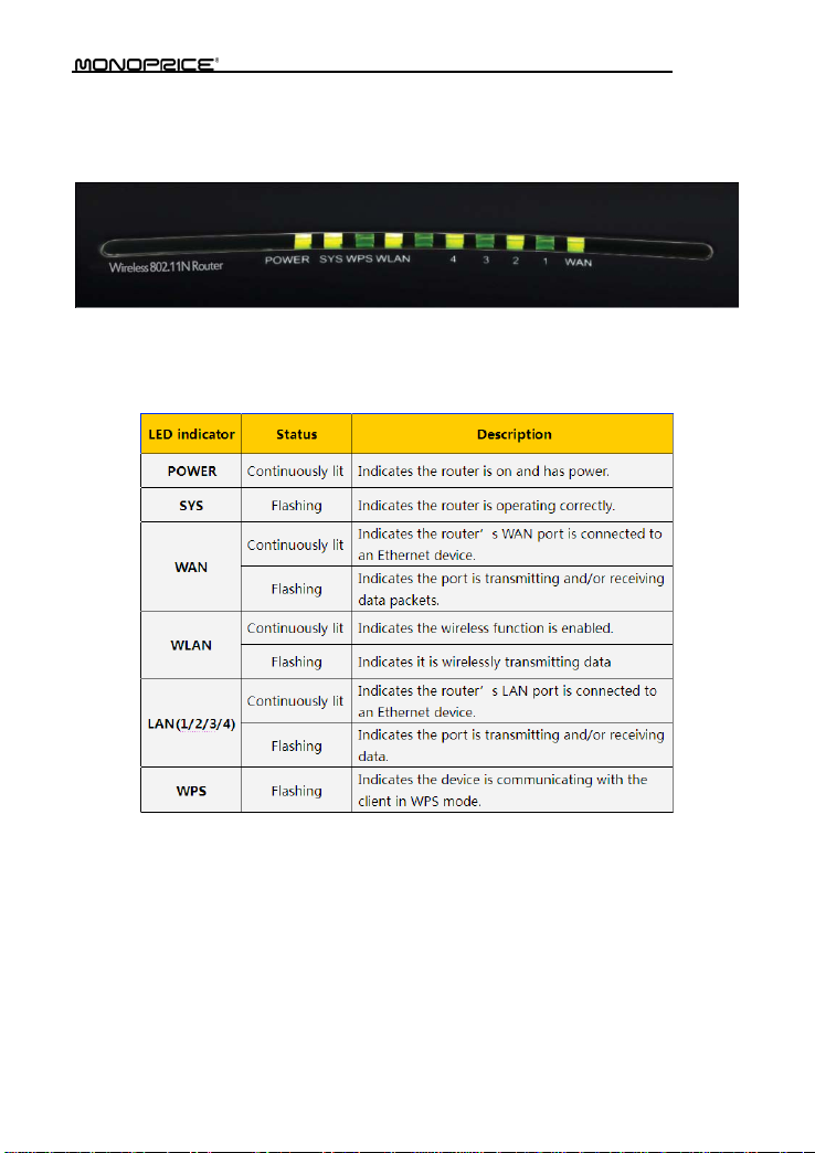
1.2 LED Indicators and Port Description
Panel and LED indicators show:
LED indicator description on the front panel
Page 8
3
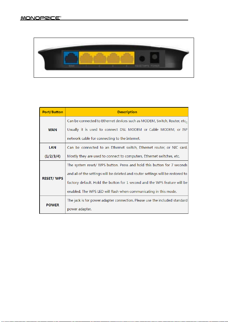
Back panel ports
Back panel port description
Page 9
4
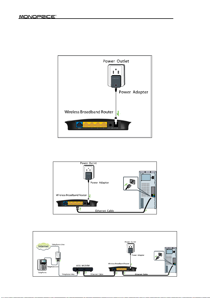
Chapter 2 Product Installation
1. Warning! Use only the included power adapter to power your route r. NOTE: Use of an
unmatched power adapter could cause damage to this produc t.
2. Connect the router's LAN port to your computer with an Et hernet cable as shown
below.
3. Connect your broadband line provided by your ISP to the router's WAN port.
Page 10

5
4. Insert the included software CD into the CD drive of your computer. After the disc has
loaded double click the Setup icon and follow the instructions to complete the
installation. You can also use the router's Web-based Utility to complete the
configuration.
Page 11
6
Chapter 3 Prepar i ng to Access the Internet
3.1 Setup the Network Configuration on Your PC
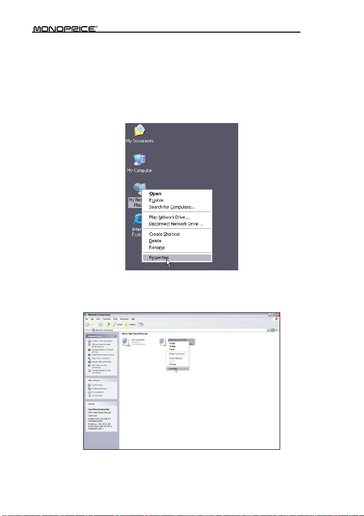
Network Configuration under windows XP
1. Right click My Network Places on your computer desktop and select Properties.
2. Right click Local Area Connection and select Properties.
Page 12

7
3. Select Internet Protocol (TCP/ IP) and click Properties.
4. Select Use the following IP address and enter the IP address , Subnet mask, Defa ult
gateway as follows:
IP Address: 192. 168.0.XXX: (XXX is a numb er from 2~254)
Subnet Mask: 255.255.255.0
Gateway: 192.168.0.1
DNS server: You should input the DNS server address provided by your ISP.
Otherwise, you can enter 192. 168.0.1. Click OK to save the configurations.
Page 13
8
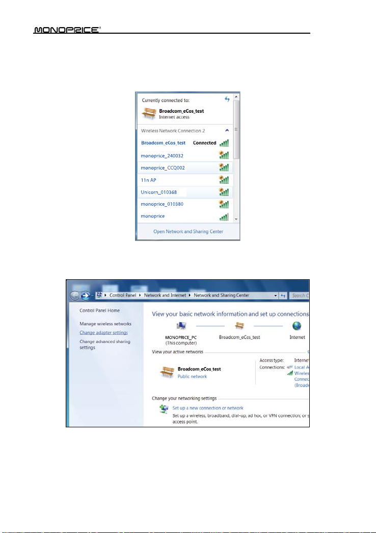
Network Configuration under windows 7
1. Click the network icon on the lower right corner of your compu ter desktop, and then
click Open Network and Sharing Center.
2. Click Change adapter settings on the left side of the window.
Page 14
9
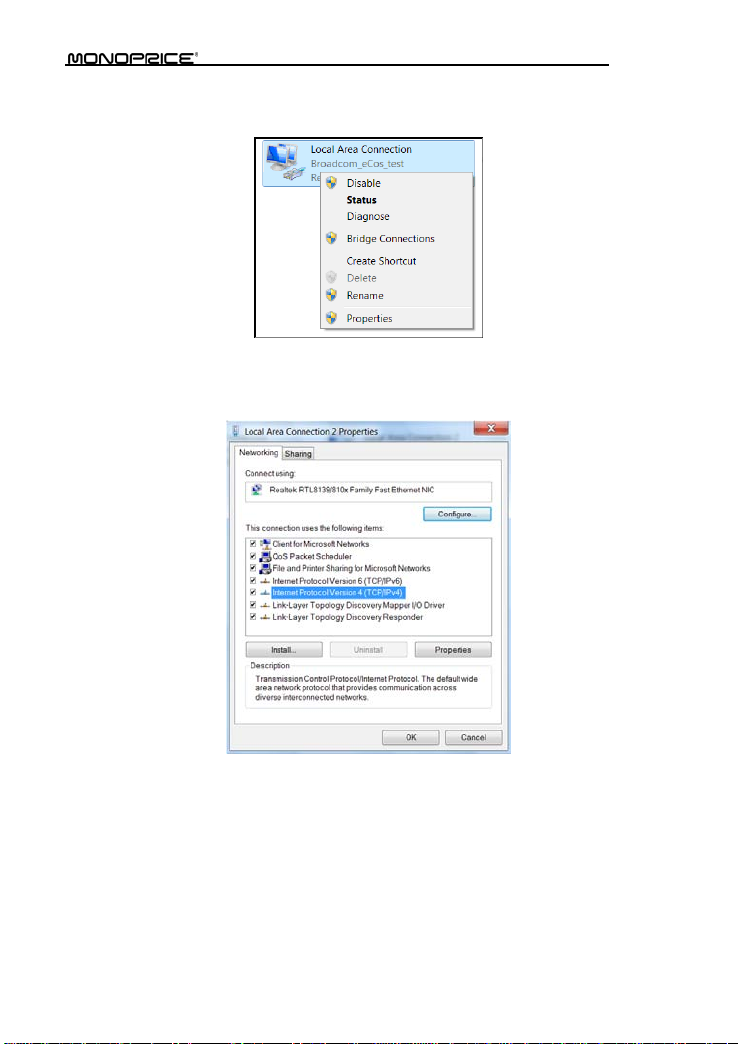
3. Right click Local Area Connection and select Properties.
4. Double clic k Internet Protocol Version 4 (TCP/IPv4).
Page 15
10
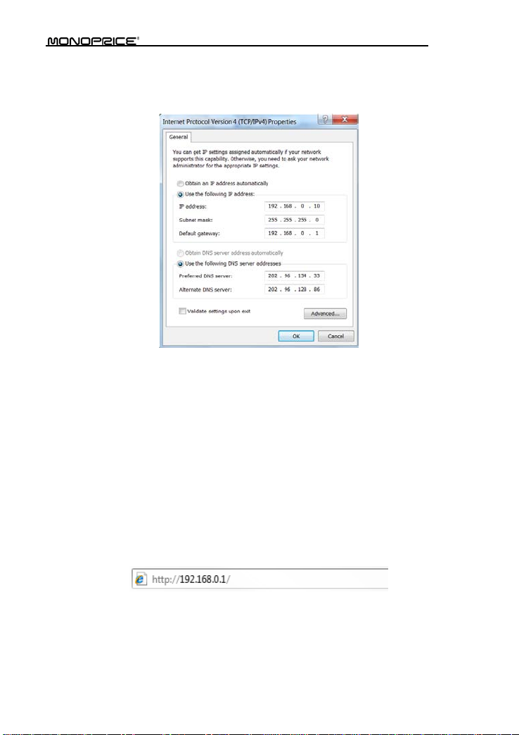
5. Select Use the following IP address and enter the IP address , Subnet mask, Defa ult
gateway as follows:
IP Address: 192. 168.0.XXX: (XXX is a numb er from 2~254)
Subnet Mask: 255.255.255.0
Gateway: 192.168.0.1
DNS server: You should input the DNS server address provided by your ISP.
Otherwise, you can enter 192. 168.0.1. Click OK to save the configurations.
3.2 Log in to the Router
To access the Router's Web-based Utility, launch a web browser such as Internet Explorer
or Firef ox and enter ht tp://192 .168.0.1. Press Enter.
Page 16

11
3.3 Fast Internet Access
Two kinds of fast acc ess methods are pr ovided on the route r's web-based utility: ADSL
Dial-up and DHCP.
If you select ADSL Dial-up, you need to enter the access account name and access
password for your ADSL account (provided by your ISP), as well as the wireless password
(default is 12345678), th e n click Ok to complete the settings.
Page 17

12
If you select DHCP, you only need to enter the w ireless pa ssword (default is 12345678) and
click Ok to complete the settings.
The default access method is ADSL Dial-up and the access account and access password
are the same as the ADSL Dial-up account and password, which you can obtain from your
Page 18

13
broadband ISP. For other access methods, please refer to WAN settings in chapter 4.The
wireless password can only consist of 8 char acters, the default is 12345678, and you can
modify it when necessary.
3.4 Fast Encryption
The router provides two encryption setting screens, one is simple and easy, the other is
advance d. For instr uc tions on using the advanced setti ng, please re f er to chapter 5.2.
Simple and easy setup:
Log on to the router's web-based utility and choose the encryption method for the router.
The default me th od uses the WP A -PSK mode and AES algorithm. The default password is
12345678, as shown below.
NOTE: The wireless password can only be 8 characters in length and the default
is 12345678. You can modif y it when nec e ssar y.
Page 19

14
Chapter 4 Advanced Settings
4.1 System Status
Click Advanced Settings > System Status to view th e router's WAN port and s ystem
status.
Connection status: Displays the router's WAN connection status.
Disconnected: Indicates the router's WAN port hasn't been connected with a
network cable.
Connecting: Indicates the router's WAN port is obtaining an IP address.
Connected: Indicates the Router is properly connected to the ISP.
WAN IP: IP address obt ained from ISP.
Subnet mask: Obtained from ISP.
Gateway: Obtained from ISP.
DNS server : Obtained from ISP.
Alternate DNS server: Obtained from ISP.
Connection type: Displays your current access method.
Page 20

15
LAN MAC address:Displays the Router's LAN MAC address.
WAN MAC address:Displays the Router' s WAN MAC Address.
System time:Displays the system 's updated time
Connected client:Displays the number of the connected computers (normally
displays the number of clients whose IP addresses are obtained via DHCP server).
Software version:Displays the Router' s sof tware version.
Hardwar e version:Displays the Router's hardwa re v ersion.
4.2 WAN Settings
Click Advanced Settings > WAN settings to configure the router's WAN settings.
Virtual Dial-up (PPPoE)
Page 21

16
Mode: Shows your current connection mode.
Access Account: Enter the acc ount provided by your ISP.
Access Password: Enter the password prov ided by your ISP.
MTU: Maximum Transmission Unit. This is the size of the lar gest data packet that
can be se nt over t he network . The de fault v alue is 14 92. Do NO T modify it u nless
necessary. If a specific website or web application software cannot open or be
enabled, you can try to c hange the MTU value to 1450, 1400, etc.
Service Name: The connection name for the curre nt PPPOE. Enter it if required,
otherwise leave it blank.
AC Name: The service name. Enter it if requi red, otherwise leave it blank.
Connect Automatically: Connects automatically to the Internet after rebooting the
system or after a connection failure.
Connect on Demand: Connects to the internet whenever internet activity is
detected (e.g., checking email). After a set period of time, the connection will be
terminated (Max I dle Time). A setting of zero m eans you will be con nected to the
Internet at al l tim es. Othe rwis e, ent er t he numb er of min utes of inac tiv ity bef ore y ou
are disconnected from the internet.
Connect Manually: Users connect to the internet manually.
Connect on Fixed Time: Connects to the internet automatically at the time specified.
NOTE:
Page 22

17
The “Connect on Fixed Time” setting goes into effect onl y when you have set the
current time in “Time settings” from the “System tools” menu.
Static IP
If your ISP prov id es you wit h a stat ic IP, please choose stat ic IP. You wil l nee d to ent er the
IP address, subnet mask, gatew ay, DNS server, and alternate DNS ser ver pro vided by yo ur
ISP or network administrator.
Mode: Shows your current connection mode.
IP address: Enter the WAN IP address provid ed by your ISP. If you are unsure of
what it is, please contact your local ISP for assistance.
Subnet mask: Enter the WAN Subnet Mask provided by your ISP. Generally it is
255.255.255.0.
Gateway: Enter the Gateway provided by your ISP. If you unsure of what it is, please
contact your local ISP for ass istance.
DNS server: Enter the necessary DNS server provided by your ISP.
Alterna te DNS s erver : Enter the secondary DNS a ddres s if yo ur ISP prov ide s one
(this is optional).
Dynamic IP (Via DHCP)
If your c onnect ion m ode is Dy namic I P, it means ever y time you access the Inter net, you
will get a different IP. You don't nee d t o en t er any parameters in this mode, just click Ok to
finish the settings.
Page 23

18
PPTP
Mode: Shows your current connection mode.
PPTP server address: The IP address or domain name of the destination server,
used to specify the destinat ion address, which is needed for a PPTP connection.
Username/Password: Used to log in to the PPTP server.
Address mode: Sets the router's IP address mode. You can select either Dynamic
or Static. If your ISP doesn't provide a fixed IP address, please select Dynamic.
IP address: Enter the IP addre ss provided by you r ISP. If you are unsure of w hat this
should be, contact your local ISP for assista nc e.
Subnet mask: Enter the subnet mask provided by your ISP, usually it is
255.255.255.0
Gateway: Enter the gateway provided by your ISP. If you ar e unsure of what t his
Page 24

19
should be, contact your local ISP for assista nc e.
All the above values are provided by your ISP.
L2TP
Mode: Shows your current connection mode.
L2TP server address: The IP address or domain name of the destination server,
used to specify the destinat ion address, which is needed for a L2TP connection.
Username/Password: Used to log in to the L2TP server.
Address mode: Set the router's IP address mode, you can select either Dynamic or
Static. If your ISP doesn't provide a fixed IP address, please select Dynamic.
IP address: Enter the IP addre ss provided by you r ISP. If you are unsure of w hat this
should be, contact your local ISP for assista nc e.
Subnet mask: Enter the subnet mask provided by your ISP, usually it is
255.255.255.0
Gateway: Enter the gateway provided by your ISP. If you ar e unsure of what t his
should be, contact your local ISP for assista nc e.
All the above values are provided by your ISP.
4.3 LAN Settings
Page 25

20
Click Advanced setti ngs > LAN setti ngs to configure the router's IP address and Subnet
Mask.
LAN MAC address: The router's LAN MAC address, which cannot be changed.
IP address: The router's LAN IP address (not your PC's IP address).The default
value is 192.168.0.1. You can change it when necessary.
Subnet Mask: The router's LAN Subnet Mask. The default value is 255.255.255.0
NOTE:
Once you modify the IP address, you need to remember it for next time you log in to
the web-based utility.
4.4 MAC Clone
Click Advanced settings > MAC Clone to view the following screen. This screen allows
you to configure the router's WAN MAC addre ss.
Page 26

21
MAC Address: Set the router' s WAN MAC address.
Clone MAC Address: Clicking this button changes the router's WAN MAC address
from the default to the MAC address of the PC you are currently using. Don't use this
button unless your PC's MAC address is the one bound by your ISP.
Restore Default MAC: Restores t he router's WAN MA C to default settings.
4.5 DNS Settings
Click Advanced settings > DNS settings t o view the following screen. DNS stands for
Domain Name System (or Service).
DNS setting: Select to enable the DNS server.
Page 27

22
Primary DNS address: Enter the necess ary DNS addres s provide d by your ISP.
Alternate DNS address: Enter the secondary DNS address if your ISP provides one
(this is optional).
NOTE:
After the settings are completed, reboot the router to activ a t e the modif ied settings.
4.6 WAN Medium Type
Click Advanced settings > WAN medium t ype to configure the type of WAN the router
will utilize (wired or wireless).
Wired WAN: In this mode, the cable is direc tly co nnected t o the WAN port. Wired
WAN is the default mode.
Wireless WAN: Enable t his mode if your ISP provides you a wireless connection
Page 28

23
service or you want to use the router to expand your wireless signal coverage.
SSID: SSID (Service Set Identifier) is the identity of the wireless device. You can only
access the ISP's network by entering the correct SSID of the ISP's wireless device.
You c an click the Open scan b utton to let the r outer aut omatica lly searc h for any
availab le SSIDs. The SSID can also be the SSID of th e primary wireless dev ice
when using the router as a wireless bridge.
MAC: To connect to the ISP's wireless devic e you need to know the device's MAC
address. You can click the Open sca n button to let the router automatically search
for an ava ilable MAC address or the primary wireless device's MAC address.
Channel: The wireless device's communication channel. You must select the same
channel as the ISP's wireless device to enable communications. It can also be
scanned by clicking the Open scan button.
Security mode: When t he ISP wireless device is s ecured, the access device should
set the same security mode, e ncryption mode, and key as the ISP's wireless device.
Example:
If your ISP's wireless device's SSID is Wireless then just enter Wireless into the SSID field,
plus the wireless MAC address and channel into the corresponding fields of th e above
picture. If the ISP d evice is secured, set your router's encryption type to the same as used
by the ISP's device. Alternatively, you can click the Open scan button to let the router
automatically fill in the SSID, Channel, and wireless MAC. After saving these values, go to
the WAN Setting screen to select the corresponding WAN connection type to complete the
configuration.
4.7 Bandwidth Control
Bandwidth control is used to limit the communication traffic of LAN computers when
accessi ng t h e I nt e rne t. It can simultaneously control the traffic fo r a m a xim um of 254 P Cs.
Additionally, IP address range configuration is also supported.
Page 29

24
Enable Bandwidth Control: Enable or disable the internal IP bandwi dt h cont rol.
The default is disabled.
IP Address: The IP address range of the connected client computers whose traffic
you want to control. It can be a single IP address or IP address range.
Upload/Download: Specifies the direction in which traffic is to be controlled for the
selected IP addresses, ei ther uploading or downloading.
Bandwidth Range: Specifies the minimum and maximum bandwidth (in KBytes/sec)
to allow for use by client computers within the specified IP range. The specified
bandwidth cannot exceed t he WAN port bandwidth limitat i on range.
Enable: Enables the rule that is currently being edited. Otherwise, the rule will not go
into effect.
Add to list: After you edit the rule, click the Add to list button to add the current rule
to the rule list. You can have multipl e rules that operate simultaneousl y.
Let's take 2Mbps bandwidth as an exa mp le. Theoretically, the fastest downloading rat e for
2Mbps bandwidt h i s 2Mbps / 8 = 256KByte/s, and the fastest uploading speed is 512kbps /
8 = 64KByte/s.
Example 1
If you want to set the maximum download rate of the computer at the IP address
192.168.0.100 to 80-90KByte/s, with a corresponding upload rate of 10-15KByte/s, first add
an upload rule as follows:
Page 30

25
1. Enter 100 - 100 in the IP address field
2. Select Upload in the Upload/Download field.
3. Enter 10 - 15 in t he Bandwidth range field
4. Click the box next to the Enable field so that it has a check mark in it.
5. Click the Add to list button.
6. Click Ok to finish setting the upload rule settings.
Next add a download rule as shown in the following image us ing the following steps, as
illustrated in the next image:
1. Enter 100 - 100 in the IP address field
2. Select Download in the Upload/Download field.
3. Enter 80 - 90 in the Bandwidth range field.
4. Click the box next to the Enable field so that it has a check mark in it.
5. Click the Add to list button.
6. Click Ok to finish setting the upload rule settings.
Page 31

26
Example 2
The following two screen sho ts depict how to set an upload rate limit of 20-30 KBytes/s and
a download rate limit of 100-120 KBytes/s for computers within the IP address range
192.168.0.2 to 192.168.0.254.
Page 32

27
These values are set using the same method as in Example 1.
4.8 Traffic Statistics
The Traffi c Statistics screen is used to display the bandwidth used by eac h con nected PC.
Enable Traffic s tatistics: Check this box to allow the router to calculate t he traffic used by
each computer connected to t he LAN. Usually it is best to leave this disabled to improve
the router's data packet processing ability, and the default is disabled. Although each
computer's traffic is constantly monitored when this function is enabled, the webpage will
Page 33

28
refres h automatically ever y five minutes .
IP address: the IP address of the computer whose traff ic is being calculated.
Uplink rate: the data sending speed per second in KBytes/s .
Downlink rate: the data receiving speed per second in K bytes/s.
Sent message: the number of data packet s sen t out through the router.
Sent Bytes: the total volume of data that is sent out through t he router.
Received message: the number of data packets rece ived through t he router.
Received Bytes: the total volume of data received through t he router.
4.9 WAN Speed
This sect ion allo ws you to confi gure the WAN sp eed. It is recommended that the default
settings are retained.
AUTO: This is th e default setting. In this mode, the router will select the best data
speed for your network. Keep this selection unless you are experiencing connection
and performance issues.
10M HALF-duplex: This is the slowest data rate. Select this value if your router's
WAN port does not function properly when connected to an Ethernet cable, whi ch
may be caused by degraded performance due to the cable's excessive length.
10M FULL-duplex: Selec t t his value to improve WAN port performance.
100M HALF-duplex: Choose t h is selection it to set the router's WAN port to work at
100Mbps in half duplex mode.
100M FULL-duplex: This is the fastest data rate. Select this value to force the WAN
Page 34

29
port to work at maximum spe e d. This will result in lost a lost da ta if an error occurs. It
is better to choose the AUTO option so that the rout er can dynamically react to
fluctuations in signal strength and reliability.
Page 35

30
Chapter 5 WLAN Settings
5.1 Wireless Basic Settings
Enable wireless function: When selected it enables the router's wireless fe atures.
When not selected, all wireless features and functions are disabled.
Wireless Working mode: Select between the two possible wireless modes:
Wireless Access Point (AP) and Network Bridge (WDS).
Wireless Access Point (AP)
Network Mode: Select one of the modes from the drop-down list:
11b mode
11g mode:Use this mode if you have only Wireless-G clients in your network.
11b/g mixed mode: Use this mode if you have only Wireless-B and Wireless-G
11b/g /n m ixe d mode: Use this m ode if y ou ha ve Wireless-B, Wireless-G, and/or
Primary SSID: This is a unique name used to identify the network and is required.
Secondary SSID: This is another unique name, whic h must be different from the
Primary SSID, and whi ch serv es as an al ter nat ive i de ntif ier. The Se con dary SSI D is
optional.
Broadcast (SSID): Select Enable to a llo w the router's SSID to be bro adcas t, whi ch
allows other wireless devices to find i t by scanning. When disabled other wireless
:Use this mode if you have only Wireless-B clients in your net work.
clients in your network .
Wireless-N clients in your network.
Page 36

31
devices must be manually configured t o use the router's SSID. This is enabled by
default.
AP Isolation: This opt ion is disabled by default, and it is recomme nded that you
leave it disabled. When enabled, wireless clients connected via the primary SSID
and wireless clients connected via secondary SSID are isolated and cannot
communic ate with each other. Enable this option only if you want to operate two
completely separate wireles s LANs, each with their own separate SSID.
Channel: The channel currently used by the router. Select an effective channel, from
1 to 11, or AutoSelect.
WMM Capable: The Wi-Fi MultiMedia mode allows the router to provide a steady
bandwidth to high-priority data streams, such as Voice Over I P (VoIP), online gaming,
and video streaming, by decreasing bandwidth to low priority streams, such as data
downloads and email. This is enabled by default and should remain so to ensure
proper QoS (Quality of Service) operation.
APSD Capable: The Aut omatic Power Sav e Deliv ery opt ion is us ed to pu t devic es
into sleep/doze status when not active and is only used with WMM. This is most
useful fo r systems that cons ist almos t enti rely of Voice ove r IP (VoIP) appli cations .
Otherwise it is best to leave this option disabled.
Channel bandwidth: This option sets the appropriate bandwidth for the router and
depends on t he type of wirele ss connecti ons in use. If the cl ients include systems
using an 11n conne c tion, sele c t the 20/40M option. If the only clients are using 11b/g
connections, then choose the 20M sett i n g.
Extension Channel: This setting determines the wireless channel on which your
router will broadcast and receiv e data. You want to make sure that the router is not
using the same channel as any other device in the same frequency range. If a
conflict occurs it can cause interference and lost data packets. In most cases, setting
this to Auto Select will ensure that no conflicts occur.
Page 37

32
Network Bridge (WDS) Settings
WDS (Wireless Distribution System) is used to expand the wireless coverage area for an
existing network.
AP MAC address: Input the MAC address of another (opposing) wireless router
whose coverage you want to expand.
Example: This example bridges two W368R routers.
Page 38

33
1. If you know the connecting router's MAC address, enter it into th e AP MAC address field
and click Ok.
2. You can also obtain the MAC address by scanning for the router's signal.
a) Click Open scan to get a list of available routers. Select the router you want to
connect to and click the Ok button on the dialog box. The corresponding wireless
MAC address will be added to the AP MAC addres s field automatically.
Page 39

34
b) After the MAC address is added , click Ok.
3. After complet ing the above steps, repeat the process with the other W368R router.
NOTE:
The WDS feature requir es that both rout ers support t his function and that the SSID,
Page 40

35
channel, encryption method, and password are the same on each connected router.
5.2 Wireless Security Settings
With the wireless security function , you can p re vent others from conne cti ng to your wireless
network and using the network resources without your consent. M eanwhile, you can also
block illegal users from intercepting or intruding into your wireless network.
5.2.1 WPS Settings
WPS (Wi-Fi Protected Setting) makes it quick and easy to establish a secure connection
between the wireless clients and the router. You only need to enter a PIN code or press the
WPS button on the back panel of the router to configure it without manually selecting an
encryption method or setting a key.
WPS setti n g s: To enable or disable WPS function. The default is Enable.
WPS mode: Selects which of two methods to use: PBC (Push-But ton Configuration )
or PIN code.
PBC: Select PBC and click Ok, or press and hold the WPS button on the back
panel of t he device for about one second. The WPS LED indicator will be
flashing for 2 minutes, which means the WPS is enabled. During this time
(flashing WPS LED), you can enable the wireless client to implement the
Page 41

36
WPS/PBC negotiation between them. When the WPS connection is
completed, the LED indicator will be continuously lit. To add more clients,
repeat the above steps.)
PIN: If this option is enabled, you need to enter a wireless client's PIN c ode in
the fiel d and use the sam e code for the W PS client.
Reset OOB: Press this button, the WPS client will be in an id le st ate, and t he W PS
indicator will turn off. The AP will not respond to the WPS client's connection request
and will set the security mode as Open-None (Disable) mode.
NOTE:
The use of the WPS function requires the use of wireless ada pter.
5.2.2 WPA-PSK
The WPA (WiFi Protected Access) method guarantees protection of WLAN users' data and
only the authorized networ k users can access the WLAN.
Security Mode: Select the proper security mode from the drop-down menu.
WPA Al gorithms: Allows the use of TKI P (Temporal Key Integrity Protocol), AES
(Advanc ed Encrypt ion Standard), or both.
Key: Enter a pass phrase that cons ists of 8-63 ASCII characters.
Key Renewal Interval: Set the key's renewal period, which tells the devic e how
Page 42

37
often it should change the dynamic keys.
5.2.3 WPA2-PSK
WPA2 (Wi-Fi Protected Access version 2) provides even higher s ecurity th an the use of
basic WPA.
WPA Al gorithms: Allows the use of TKI P (Temporal Key Integrity Proto col), AES
(Advanc ed Encrypt ion Standard), or both.
Key: Enter a pass phrase that cons ists of 8-63 ASCII characters.
Key Renewal Interval: Set the key's renewal period, which tells the device how
often it should change the dynamic keys.
Page 43

38
5.2.4 WEP
The WEP (Wired Equivalent Privacy) is an encryption method that encrypts the data
transferred wirelessly between devices to prev ent unauthorized users from intercepting or
invading the wireless network. WEP security, based on RC4 data e ncryption technology,
provides data confidentiality, integrity, and authentication for wireless communications.
Security Mode: Selec t t he c or r es pond i ng s ec u r it y mo d e from t he dr op-down menu.
The Open option is m ore secure a nd is preferr ed over the Shared method.
WEP Key1~4: Set the W EP ke y s using eithe r ASCII or Hex format. ASCII c odes use
5 or 13 ASCII characters (illegal characters such as "/" are not allowed). Hex keys
use 10 or 26 hexadecimal characters (0-9 and A-F).
Default Key: Selec t one of the four preset keys to use as the current default one.
Page 44

39
5.3 Wireless Access Control
Wireless ac cess cont rol is b ased on the M AC address to permit or forbid specific cli ents'
access to the wireless network.
MAC address filter: The Permit option allows the specified clients in the list access
to the wireless network, while the Forbid option prevents t h e s p ec if ie d c l ien ts in t he
list from accessing the wireless network.
Configure MAC address: Input the MAC addresses of the wireless clients to
implement the filter policy. Click Add to finish the MAC addition operation.
MAC Address list: Displays the filt ered MAC addresses. You can add or delete
them individually.
5.4 Connection Status
This screen shows the wireless client's connection status, including the MAC address and
channel bandwidth.
Page 45

40
MAC address: Shows the MAC addresses of the clients connected to the router.
Bandwidth: Shows the channel bandwidth of the currently connected wireless
clients.
Page 46

41
Chapter 6 DHCP Server
6.1 DHCP Server
The DHCP (Dynamic Host Control Protocol) is used to assign an IP address to the
computers on the LAN/private net work. W hen you enable the DHCP Server, the DHCP
Server will automatical ly allocate an unus ed IP address from th e IP address pool to the
requesting computer. You must specify the starting and ending address for the IP Address
pool.
DHCP server: Check the Enable box to e nable the DHCP server.
IP pool start/end address: Enter the range of IP addresses for DHCP server
distribution.
Lease time: This indicates the length of time that a dynamic IP addr ess may be
assigne d to a sp ec i fi c cl i ent by th e DHCP s erv er. Duri n g th is tim e, t he se rv er wil l n o t
attempt to assign the IP address to any other client computer.
Page 47

42
6.2 DHCP Client List
The DHCP client list displays client c om put e r IP a ddr esses, MAC addresse s, host names,
and other information assigned by the DHCP server. You can manu ally enter the IP and
MAC address to convert an IP into a static assignment for the specified client.
IP address: You can specify an IP address for static binding.
MAC address: Enter the MAC address of the computer you want to give static
binding. Click Add to add the e ntry in the list.
Host Name: Displays the name of the computer whose IP is allocated by the DHCP
server.
IP Address: Displays the IP address of the client computer.
MAC address: Displays the MAC address of the client computer.
Lease time: Displays the amount of time remaining on the client's IP address lease.
Page 48

43
Chapter 7 Virtual Server
7.1 Port Range Forwarding
Port Range Forwarding allows you to specify which IP address is to receive incoming da ta
over specific ports. This is useful when running an application that will receive data from the
internet on a specific por t, or port range, without having first sent out data to the internet on
the same port (e.g., when running a web server, ftp host, etc.
Start/End port: Enter the starting and ending port numbers to be forwarded to t he
specific cli ent computer .
LAN IP: Enter th e I P add r ess of t he c l ie nt c om p ut er whi c h wil l r ec e iv e t he da ta s en t
through the specified ports.
Protocol: S elect the pr otoco l (TCP, UDP, or Both ) for th e applic atio n. If you are not
clear about the protocol that will be used, select Both.
Enable: Click the Enable checkbox to put the rule int o ef fect.
Delete: Clears all the settings of this line when the Ok button is clicke d.
Well-known service port: The well-known protocol ports are listed in the drop-down
list. Select one and select a seq uence numbe r in the ID drop-down list and then click
Add to and this port will be added automatic all y to the ID list. For other well known
service ports that are not listed, you can manually add them to the list.
Add to: Adds the s elected well-known port to the policy ID.
For Example: You want to share some large files with your friends outside of your local
Page 49

44
area network. However , they are too big, and it's not convenient to physically transfer them.
You can build a FTP server on your computer and set the router's port range forwarding to
give you r fr iends acc ess to th ese f iles on yo ur com puter. For the purpose of this exam ple,
suppose that your FTP server (or your computer's static IP address) is 192.168.0.10 and
you want your friends to access the server through the default port 21 using the TCP
protocol. You would then perform the following steps:
1. Enter 2 1 in both the Start por t and End port fi elds. Alternatively, you can select FTP from
the well-known service port list and port 21 will be added to the corresponding fields
automatically.
2. Enter 192.168.0.10 in the LAN IP column.
3. Select Both as the protocol.
4. Check the box under Enable.
5. Click the Ok button to put the rul e into effect.
Now, when your friends want to visit the FTP server, they only need to
enter ftp://xxx.xxx.xxx.xxx:21 in the address field. Here, xxx.xxx.xxx.xxx is the router's WAN
IP address. For example, when your router's WAN IP address i s 172.16.1 02.89 your friend s
need to enter ftp://172.16.102.89:21 in the address field.
NOTE:
If you set the service port of the virtual server to 80, you must set the Web
 Loading...