

Page 1

MP Education Guider II 3D Printer
P/N 30527
User's Manual
Page 2

CONTENTS
SAFETY WARNINGS AND GUIDELINES ....................................................................................................................................... 5
CUSTOMER SERVICE .................................................................................................................................................................................... 6
PACKAGE CONTENTS ................................................................................................................................................................................. 6
PRODUCT OVERVIEW ................................................................................................................................................................................. 8
Front View...................................................................................................................................................................................................... 8
Top View .......................................................................................................................................................................................................... 8
Right Side View ......................................................................................................................................................................................... 8
Rear View ........................................................................................................................................................................................................ 9
OSD MENU SYSTEM .................................................................................................................................................................................... 9
Top Menu ........................................................................................................................................................................................................ 9
Build Menu ..................................................................................................................................................................................................... 9
Print Menu.................................................................................................................................................................................................... 10
Print Progress Screen ......................................................................................................................................................................... 10
More Menu ................................................................................................................................................................................................... 11
Preheat Menu ............................................................................................................................................................................................. 11
Preheat Temperature Screen ...................................................................................................................................................... 12
Preheating Screen ................................................................................................................................................................................. 12
Tools Menu .................................................................................................................................................................................................. 13
Manual Adjustment Screen .......................................................................................................................................................... 13
Setting Menu ............................................................................................................................................................................................. 14
Status Screen ............................................................................................................................................................................................. 15
About Screen ............................................................................................................................................................................................. 15
WiFi Screen .................................................................................................................................................................................................. 16
WLan Hotspot Screen ........................................................................................................................................................................ 17
2
Page 3

Setup WLAN Hotspot Screen ..................................................................................................................................................... 17
UNPACKING ...................................................................................................................................................................................................... 18
HARDWARE ASSEMBLY ........................................................................................................................................................................ 20
LOADING FILAMENT ................................................................................................................................................................................. 21
UNLOADING FILAMENT ........................................................................................................................................................................ 22
BUILD PLATE LEVELING ......................................................................................................................................................................... 24
MP FLASHPRINT SOFTWARE ............................................................................................................................................................ 26
Installation .................................................................................................................................................................................................. 26
Initial Setup ................................................................................................................................................................................................ 27
Main Interface Overview ............................................................................................................................................................... 28
Loading a File ........................................................................................................................................................................................... 29
Generating a Model ............................................................................................................................................................................ 30
Changing Views ..................................................................................................................................................................................... 32
Model Manipulation ........................................................................................................................................................................... 34
Supports ........................................................................................................................................................................................................ 36
Printing a Model .................................................................................................................................................................................... 38
File Menu ....................................................................................................................................................................................................... 41
Edit Menu ..................................................................................................................................................................................................... 42
Print Menu................................................................................................................................................................................................... 43
View Menu ................................................................................................................................................................................................. 43
Tools Menu ................................................................................................................................................................................................ 44
Help Menu ................................................................................................................................................................................................... 46
CONNECTING THE PRINTER ................................................................................................................................................................ 46
USB Connection ..................................................................................................................................................................................... 46
WLAN Hotspot Connection ........................................................................................................................................................ 47
3
Page 4

Wi-Fi Connection ................................................................................................................................................................................. 48
UPDATING THE FIRMWARE ................................................................................................................................................................ 49
PRINTING ............................................................................................................................................................................................................ 50
Generating Gcode ................................................................................................................................................................................ 50
SPECIFICATIONS ........................................................................................................................................................................................... 53
TECHNICAL SUPPORT .............................................................................................................................................................................. 54
REGULATORY COMPLIANCE ............................................................................................................................................................. 54
Notice for FCC ......................................................................................................................................................................................... 54
Notice for Industry Canada .......................................................................................................................................................... 55
EU Declaration of Conformity ................................................................................................................................................... 55
WEEE Information ................................................................................................................................................................................ 56
Safety Notice ............................................................................................................................................................................................ 57
4
Page 5

SAFETY WARNINGS AND GUIDELINES
Please read this entire manual before using this device, paying extra attention to these
safety warnings and guidelines. Please keep this manual in a safe place for future reference.
Take care to avoid touching hot parts, including heat blocks, extruder nozzle, and
the extruded filament.
Do not wear gloves when operating or repairing to avoid entanglement.
Keep the printer and all accessories out of reach of children.
Do not remove or disconnect the USB cable when printing from a computer.
Do not force or tear anything during unpacking and setup. This may cause damage
to the printer and/or its accessories.
Do not reach inside the printer during operation.
Always allow the printer and extruded filament to cool before reaching inside.
Ensure that the printer is turned off and unplugged from its power source before
making repairs or performing service.
Do not install this device on an unstable surface where it could fall and cause either
personal injury or damage to the device and/or other equipment.
Do not subject the product to extreme force, shock, or fluctuations in temperature
or humidity.
This device is intended for indoor use only.
Do not expose this device to water or moisture of any kind. Do not place drinks or
other containers with moisture on or near the device. If moisture does get in or on
the device, immediately unplug it from the power outlet and allow it to fully dry
before reapplying power.
Do not touch the device, the power cord, or any other connected cables with wet
hands.
Use only in a well-ventilated area. Do not use in close, confined spaces.
Prior to operation, check the unit and power cord for physical damage. Do not use if
physical damage has occurred.
5
Page 6

Before plugging the unit into a power outlet, ensure that the outlet provides the
1x 3D printer
1x Spool filament
1x User's manual
1x Thank you card
same type and level of power required by the device.
Unplug this device from the power source when not in use.
Take care to prevent damage to the power cord. Do not allow it to become
crimped, pinched, walked on, or become tangled with other cords. Ensure that the
power cord does not present a tripping hazard.
Never unplug the unit by pulling on the power cord. Always grasp the connector
head or adapter body.
CUSTOMER SERVICE
The Monoprice Customer Service department is dedicated to ensuring that your ordering,
purchasing, and delivery experience is second to none. If you have any problem with your
order, please give us an opportunity to make it right. You can contact a Monoprice
Customer Service representative through the Live Chat link on our website
www.monoprice.com during normal business hours (Mon-Fri: 5am-7pm PT, Sat-Sun: 9am-
6pm PT) or via email at support@monoprice.com
PACKAGE CONTENTS
Please take an inventory of the package contents to ensure you have all the items listed
below. If anything is missing or damaged, please contact Monoprice Customer Service for a
replacement.
6
Page 7

1x Warning card
1x Lid
1x AC power cord
1x USB cable
1x USB stick
1x Spool holder
1x Filament guide
tube
1x Phillips
screwdriver
1x Allen wrench set
1x Package grease
1x Unclogging pin
tool
1x Wrench
1x Solid glue
7
Page 8

PRODUCT OVERVIEW
Front View
1. Touch screen
2. Touch screen button
3. Nozzle
4. Z-axis guide rod
5. Build plate
6. Leveling knob
Top View
7. Extruder
8. X-axis guide rod
9. Filament intake
10. Spring presser
Right Side View
11. Ethernet input
12. USB cable input
13. USB stick input
8
Page 9

Rear View
14. Filament detector
15. Power switch
16. Power input
OSD MENU SYSTEM
Top Menu
The Top Menu is displayed after the printer is powered on and initialized.
Touch the Build button to enter the
Build Menu.
Touch the Preheat button to enter the
Preheat Menu.
Touch the Tools button to enter the
Tools Menu.
Build Menu
The Build Menu is displayed by touching the Build button from the Top Menu.
Touch the Internal Memory button to
read the print file from internal memory.
Touch the USB Stick button to read the
print file from the USB stick.
Touch the Back button to return to the
previous menu.
9
Page 10

Print Menu
The Print Menu is displayed after selecting a print file from internal memory or the memory
stick. The print filename is displayed along with an estimate of the amount of time the
print process will consume.
Touch the Build button to start printing
the loaded print file.
Touch the Copy button to copy the
loaded print file.
Touch the Delete button to delete the
loaded print file.
Touch the Back button to return to the
previous menu.
Print Progress Screen
The Print Progress Screen is displayed while printing is in progress. It shows the print
filename, the actual and target temperatures, and the print progress with the remaining
time displayed.
Touch the Stop button to cancel the
print in progress.
Touch the Pause button to pause the
print. Touch it again to resume printing.
Touch the More button to display the
More Menu.
10
Page 11

More Menu
The More Menu is displayed by touching the More button on the Print Progress Screen.
Touch the Filament button to change
filament during printing. Note that the
print must be paused first.
Touch the Back button to return to the
Print Progress screen.
Preheat Menu
The Preheat Menu is displayed by touching the Preheat button on the Top Menu.
Touch the button next to the Extruder
label to turn extruder heating on or off.
Touch the button next to the Platform
label to turn platform heating on or off.
Touch the Temperature buttons to set
the target extruder or platform
temperature. The default target
extruder temperature is 220°C and 110°C for the platform.
Touch the Start button to start preheating the extruder and/or platform.
Touch the Back button to return to the previous menu.
11
Page 12

Preheat Temperature Screen
The Preheat Temperature Screen is displayed by touching one of the Temperature buttons
on the Preheat Menu.
Touch an individual digit to select the
digit to change.
Touch the - button to decrease the
value of the highlighted digit.
Touch the + button to increase the
value of the highlighted digit.
Touch the Yes button to save the displayed temperature value and return to the
previous screen.
Touch the No button to cancel any changes and return to the previous screen.
Preheating Screen
The Preheating Screen is displayed during the preheating process. It displays the
preheating progress, as well as the actual and target temperatures.
Touch the Abort button to abort the
preheating process.
Touch the Back button to return to the
previous screen.
12
Page 13

Tools Menu
The Tools Menu is displayed by touching the Tools button on the Top Menu.
Touch the Filament button to load or
unload filament.
Touch the Level button to level the
build plate.
Touch the Home button to move the
extruder to the home position.
Touch the Manual button to display the
Manual Adjustment Screen.
Touch the Setting button to display the Setting Menu.
Touch the Status button to display the Printer Status Screen.
Touch the About button to display About Screen.
Touch the Back button to return to the previous menu.
Manual Adjustment Screen
The Manual Adjustment Screen displays the X and Y positions of the extruder and the Z
position of the build plate.
Touch the X+ button to move the
extruder to the right.
Touch the X- button to move the
extruder to the left.
Touch the Y+ button to move the
extruder towards the back of the
printer.
Touch the Y- button to move the extruder towards the front of the printer.
Touch the Z+ button to raise the build plate.
13
Page 14

Touch the Z- button to lower the build plate.
Touch the Back button to return to the previous menu.
Setting Menu
The Setting Menu is displayed by touching the Setting button on the Tools Menu.
Touch the Language label to select the
language for the OSD Menu System.
Touch the Resume Print button to
enable or disable print resuming.
Touch the WiFi label to display the WiFi
Screen.
Touch the WLan hotspot label to
display the WLan Hotspot Screen.
Touch the Down button to display the
second page of the Setting Menu.
Touch the Back button to return to the
previous menu.
Touch the Polar Cloud Connection label
to enable or disable the polar cloud
connection feature.
Touch the Extruder Calibration label to
adjust the distance between the nozzle
and the build plate.
Touch the Startup Sound label to turn
the startup sound on or off.
Touch the Filament Check button to enable or disable filament checking.
Touch the Light Bar Control option to turn light bar control on or off.
14
Page 15

Touch the Factory Reset label to reset the printer's settings to their factory default
values.
Touch the Update label to update the printer's firmware.
Touch the Up button to display the first page of the Setting Menu.
Touch the Back button to return to the previous menu.
Status Screen
The Status Screen is displayed by touching the
Status button on the Tools Menu. It displays
the real-time status of the printer.
Touch the Back button to return to the
previous menu.
About Screen
The About Screen is displayed by touching the
About button on the Tools Menu. It displays
basic information about the printer.
Touch the License button to display the
License information.
Touch the Back button to return to the
previous menu.
15
Page 16

WiFi Screen
The WiFi Screen is displayed by touching the WiFi label on the Setting Screen. The Wi-Fi®
function allows you to connect the Guider II to a local Wi-Fi Access Point (AP)/hotspot, i.e.,
the one your computer is normally connected with. You can then connect to the printer in
MP FlashPrint in Station Mode (STA) without changing your computer's network settings
Touch the WiFi button to enable or
disable Wi-Fi.
When Wi-Fi is enabled, touch the name
of the Wi-Fi network to select it.
Touch the Up button to display the
previous page of the Wi-Fi network list.
Touch the Down button to display the
next page of the Wi-Fi network list.
Touch the Back button to return to the
previous menu.
16
Page 17

WLan Hotspot Screen
The WLan Hotspot Screen is displayed by touching the WLan hotspot label on the Setting
Menu. The MP Guider II printer contains a built-in Wi-Fi® radio, which can be configured as
a Wi-Fi Access Point (AP)/hotspot. You can then connect to the printer in MP FlashPrint by
changing the Wi-Fi connection on your computer to the Wi-Fi address of the printer.
Touch the WLAN hotspot button to
enable or disable the WLAN hotspot.
Touch the Setup WLAN hotspot button
to display the Setup WLAN Hotspot
Screen.
Touch the Back button to return to the
previous menu.
Setup WLAN Hotspot Screen
The Setup WLAN Hotspot Screen is displayed by touching the Setup WLAN hotspot
button on the WLan Hotspot Screen.
Touch the SSID name field to set the
WLAN hotspot name.
Touch the Password field to set the
WLAN hotspot password.
Touch the Save button to save the
settings.
Touch the Back button to return to the
previous menu.
17
Page 18

UNPACKING
1. Place the box on a flat, clean work surface.
2. Open the box. Remove the two pieces of styrofoam packing, then lift the printer
out of the box and place it on the work surface.
3. In the bottom of the carton you can find a spool of filament, the spool holder, a
power cord, a USB cable, a filament guide tube, a glue stick, and a tool bag
containing a USB stick, two Allen wrenches, a stamping wrench, an unclogging tool,
a package of grease, and a screwdriver.
4. Remove the plastic wrap from the outside of the printer.
18
Page 19

5. Remove the styrofoam packing from the top of the printer.
6. Cut the four zip ties that hold the guide rods in place. Manually move the extruder
to ensure that it moves freely along the guide rods.
7. Remove the top cover from inside the printer.
Congratulations, you have successfully unpacked your new printer!
19
Page 20

HARDWARE ASSEMBLY
Perform the following steps to perform final assembly.
1. Insert the tab on the filament holder into the hole on the back of the printer, as
shown in the images below.
2. Place the spool of filament on the filament holder. Thread filament through the
filament detecting mechanism on the rear of the printer.
3. Feed the filament through the filament guide tube.
20
Page 21

4. Insert the filament guide tube into the filament detection mechanism.
5. Ensure the power switch is in the OFF position. Plug one end of the included power
cord into the power input on the printer, then plug the other end into a nearby AC
power outlet.
LOADING FILAMENT
Perform the following steps to load filament into your 3D printer.
1. Flip the power switch on the printer to the ON position.
2. Wait for the printer to stabilize, then touch the Tools button on the Top Menu.
21
Page 22

3. Touch the Filament button, then touch the Load button. The printer will start
heating the extruder and platform.
4. Once the target temperature is reached, the printer will beep to let you know it is
ready for the next step. Insert the filament into the filament intake hole on the top
of the extruder.
5. Continue pushing filament into the extruder until filament starts to come out of the
nozzle, then touch the Done button.
Congratulations, you have successfully loaded filament into your printer!
UNLOADING FILAMENT
Perform the following steps to unload filament from the printer.
1. Flip the power switch on the printer to the ON position.
22
Page 23

2. Wait for the printer to stabilize, then touch the Tools button on the Top Menu.
3. Touch the Filament button, then touch the Unload button. The printer will start
heating the extruder and platform.
4. Once the target temperature is reached, the printer will beep to let you know it is
ready for the next step. Hold the spring presser down, then push down on the
filament for three seconds before pulling the filament out of the extruder. Do not
use force in removing the filament.
Congratulations, you have successfully uninstalled filament from your printer!
23
Page 24

BUILD PLATE LEVELING
The Guider II features a 3-point intelligent leveling system, which gives clear and
comprehensive feedback. There are three, spring-loaded knobs under the build plate.
Turning the knobs counterclockwise (when viewed from above) increases the distance
between the build plate and the extruder nozzle. Turning them clockwise (when viewed
from above), decreases the distance between the build plate and the extruder nozzle.
Perform the following steps to level the build plate.
1. With the printer powered ON, touch the Tools button on the Top Menu.
2. Touch the Level button, then wait while the Extruder and Build Plate finish their
initial movements.
24
Page 25

3. Turn the three spring-loaded knobs under the Build Plate counterclockwise until
you cannot turn them anymore, then touch the OK button.
4. Wait while the printer checks the distance between the build plate and the
extruder nozzle at the first leveling point.
5. Turn the knob under the leveling point clockwise (when viewed from above), until
the printer beeps.
25
Page 26

6. Touch the Verify button. The printer will check the distance again.
7. If the distance is correct, touch the OK button to proceed to the next leveling point.
If not, follow the onscreen instructions until the distance is correct and the OK
button is displayed.
8. Continue following the onscreen instructions until all three points are properly
leveled and the Completed Screen is displayed. Touch the Finish button to
complete the leveling process.
Congratulations, you have successfully leveled the Build Plate!
MP FLASHPRINT SOFTWARE
Installation
The Guider II 3D printer uses MP FlashPrint slicing software to create print files or to print
directly from the computer via a wired USB or wireless connection. MP FlashPrint is
available for Microsoft® Windows® and Linux®, in both 32-bit and 64-bit versions, as well as
Apple® Mac® OS X®. The MP FlashPrint installation packages can be found on the included
USB stick.
26
Page 27
Once you have located the software installation package, run the application and follow
the onscreen installation instructions.
Initial Setup
Once MP FlashPrint has been installed, double-click the application shortcut to start the
program. If this is the first time the program has been run, you will be presented with a
dialog asking you to select the Machine Type. Choose the MP Guider II entry.
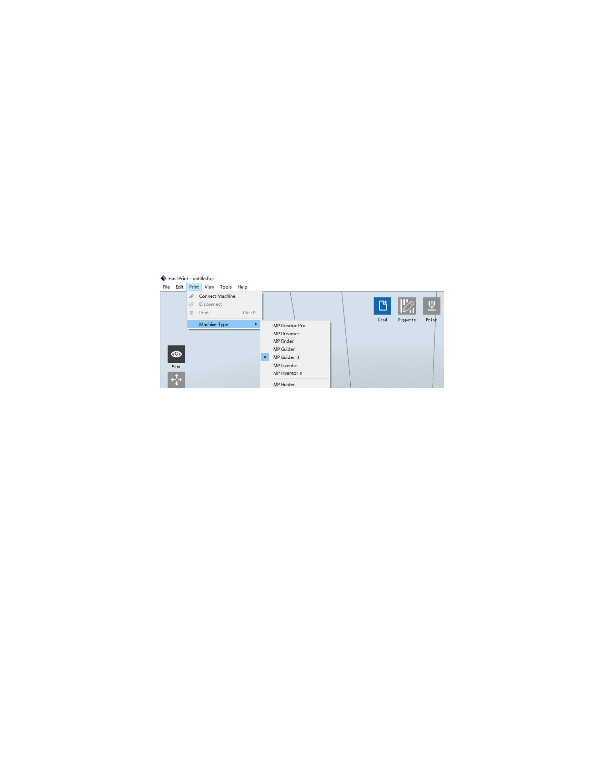
You can also select the Machine Type from within the program by clicking Print > Machine
Type > MP Guider II, as shown in the screenshot below.
27
Page 28

Main Interface Overview
Icon
Function
Load
Loads a model or Gcode file. MP FlashPrint supports .STL, .OBJ, and .FPP
model files. You can also load a .PNG, .JPG, .JPEG, or .BMP file and MP
FlashPrint will generate a model from the image. See the
Generating a
Model
section for details.
Supports
Enters the Support Edit mode.
Print
Prints directly from MP FlashPrint via a USB or wireless connection or
exports a Gcode file to the USB stick.
The screenshot below shows the three main elements of the software - the Menus, the
Icons, and the Build Platform.
The icons have the functions listed in the table below.
28
Page 29

View
Views the MP FlashPrint home screen from one of six viewing angles.
Move
Moves the model around on the X/Y plane. Hold the SHIFT key then click
to move the mode along the Z axis.
Rotate
Turns and rotates the model.
Scale
Scales the size of the model.
Cut
Cuts the model into several parts.
Loading a File
MP FlashPrint supports six different ways to load a model or Gcode file, as outlined below.
Click the Load icon on the main interface, then select the file.
Drag and drop the file onto the main interface.
29
Page 30

Click File > Load File, then select the file.
Click File > Load Examples to load one of the sample files.
Click File > Recent Files, then select the file from the list of recently used files.
Drag and drop the file onto the MP FlashPrint icon on the desktop to launch MP
FlashPrint and load the file.
Generating a Model
MP FlashPrint can generate a 3D model file from a .PNG, .JPG, .JPEG, or .BMP image file.
When you load the image file, the following dialog box will be displayed, which allows you
to set several model parameters.
Shape: Determines the basic shape of the
model. You can select Plane, Tube, Canister,
Lamp, or Seal basic shapes.
Mode: Selects whether the light or dark
portions of the image will be the high
points of the model.
Maximum Thickness: Sets the Z value of the
model.
Base Thickness: Sets the minimum raft
thickness. The default value is 0.5mm.
Width: Sets the X value of the model.
Depth: Sets the Y value of the model.
Bottom Thickness: Sets the thickness of the bottom of tube, canister, and lamp type
models.
Top Diameter: Sets the diameter for the top of tube, canister, and lamp type models.
Bottom Diameter: Sets the diameter for the bottom of tube, canister, and lamp type
models.
30
Page 31

The following screenshots illustrate the five basic shapes.
Plane
Tube
Canister
31
Page 32

Lamp
Seal
Changing Views
You can change the camera angle in relation to the model and build area using a variety of
methods.
Drag: Click the View icon, then drag the camera using one of the following methods.
Left click and hold, then move the mouse.
Click and hold the mouse wheel, then scroll up or down.
Hold down the SHIFT key, right click and hold, then move the mouse.
32
Page 33

Rotate: Click the View icon, then rotate the camera using one of the following
methods.
Right click and hold, then move the mouse.
Hold down the SHIFT key, left click and hold, then move the mouse.
Scale: Scroll the mouse wheel up or down to zoom the camera in or out.
Set View: You can select one of six preset camera angles using one of the following
methods.
Click the View menu, then select one of the six options from the drop-down list.
Click the View icon, then click it again and a submenu will appear with six
options for selection.
Reset View: You can reset the camera angle to the default using one of the following
methods.
Click the View menu, then select Home View.
Click the View button, the click it again and a submenu will appear. Select the
Reset option.
Show Model Outline: You can set MP FlashPrint to show the model outline highlighted
in yellow. To do so, click the View menu, then select the Show Model Outline
option.
Show Steep Overhang: When the intersection angle between the model surface and a
horizontal line is within the overhang threshold value, the surface has steep
overhang and is shown in red when Show Steep Overhang is enabled. To enable or
disable Show Steep Overhang, click the View menu, then select the Show Steep
Overhang entry. The default threshold value is 45 degrees.
33
Page 34

Model Manipulation
You can manipulate the model using a variety of methods.
Move: Click on the model to select it. You can then move it around the build area in a
variety of ways.
To move the model horizontally in the X/Y plane, left click and hold on the
model, then move the mouse.
To move the model vertically in the Z plane, hold down the SHIFT key, left click
and hold on the model, then move the mouse.
Click the Move button, then enter the distance value. Click Reset to reset the
distance values.
Note: After moving the model, click Center > On Platform to ensure that the
model is in the build area and in contact with the build platform.
Rotate: Click on the model to select it. You can then rotate the model in all three planes
in a variety of ways.
Click the Rotate icon and three mutually perpendicular rings will appear around
the model. Click and hold on one ring and move the mouse to rotate the model
in that plane.
Click the Rotate icon, then manually enter rotation angle values. Click Reset to
reset the rotation angle values.
Scale: Click on the model to select it. You can then scale it in a variety of ways.
Click the Scale icon, then hold the button and move the mouse to change the
scale. The corresponding values will display near the model.
Click the Scale icon, then enter scales values for the X, Y, and Z axes.
Click the Scale icon, then click the Maximum button to get the largest size
possible for the build area.
Click the Scale icon, then click the Reset button to reset the size of the model.
Note that if the Uniform Scaling radio button is enabled, it will scale the model
in proportion when changing any size value.
34
Page 35

Cut: Click the model to select it, then double-click the Cut icon to set the cut plane in a
variety of ways.
Left click and drag the cursor across the model to set the cut angle.
Select the X Plane option to cut the model vertically.
Select the Y Plane option to cut the model vertically.
Select the Z Plane option to cut the model horizontally.
35
Page 36

Supports
Because 3D printing is an additive process, each layer of filament needs a base to build on.
The printer can gradually increase the layer size, so long as the overhang angle is less than
about 45 degrees. Otherwise, you need to create support elements to serve as the base for
adding additional layers. To edit the supports, click the Edit menu, then select the Supports
entry. Alternatively, click the Supports icon. Click the Back button when finished editing
the supports.
36
Page 37

Support Options: Click the Support Options button to display the Support Options
dialog. You can select Treelike or Linear supports. Treelike supports are built at
angles, while Linear supports are linear, vertical supports for the overhanging
elements. When you click the OK button, the software will generate the appropriate
support structures. If the model already has supports, the software will judge
whether the existing supports need to be deleted or not on the basis of the type of
existing support, and display the corresponding prompt to let you make the choice.
Auto Supports: Click the Auto Supports button to allow the software to judge where
supports are needed and will generate corresponding treelike or linear supports. If
the model already has supports, the software will delete them and new supports
will be generated.
Add Supports: Click the Add button to manually generate supports. Move the cursor to
the position where a support is needed, left click to choose the starting point, then
while holding down the mouse button, drag the mouse to the termination point.
The supports preview will be displayed with the support highlighted. If the support
surface doesn't need support or the support column angle is too large, the support
will not be generated.
Clear Supports: Click the Clear Supports button to remove all existing supports. If you
change your mind, click the Undo option or press CTRL+Z.
37
Page 38

Delete Supports: Click the Delete Supports button to remove individual supports. Click
the cursor on the support you want to remove to highlight that support and all
subnode supports, then click the left mouse button to delete the highlighted
support.
Printing a Model
Click the Print icon on the main interface to slice the model and print the resulting Gcode
file, either directly from MP FlashPrint or by first exporting it to the USB stick.
Preview: Check the Preview box to preview the model before slicing and printing.
Print When Slice Done: Check the Print When Slice Done box to start the print as soon
as the slice is completed.
Material Type: Select the filament type in use.
Supports: Enable or disable the creation of supports.
Raft: Enables or disable a Raft, which is several layers of material on the build plate to
help with model adhesion.
38
Page 39

Wall: Check the Wall box to help clear leaking filament from a second extruder during
dual color printing.
Brim: Check the Brim box to print a ring of filament around the model to help prevent
warping and assist with bed adhesion.
Resolution: For ABS and PLA printing, you can choose Low, Standard, or High
resolution. For PLA printing, you can also choose Hyper. The higher the resolution,
the smoother the model surface, but at a corresponding cost in print speed.
More Options: Click the More Options button to reveal tabs with additional options.
Layer: Click the Layer tab to reveal the layer options.
Layer Height: Sets the thickness of each layer. The thinner the layer, the
smoother the model surface, but at a corresponding cost in print speed.
First Layer Height: Sets the thickness of the first layer of the model, which
affects how well the model adheres to the build plate. The maximum thickness
is 0.4mm and the default value is usually sufficient.
Shell: Click the Shell tab to reveal the shell options.
Perimeter Shells: Sets the number of perimeter shells. The maximum value is 10.
Top Solid Layers: Sets the number of solid layers at the top of the model. The
maximum value is 30 and the minimum is 1.
Bottom Solid Layers: Sets the number of solid layers at the bottom of the model.
The maximum value is 30 and the minimum is 1.
Infill: Click the Infill tab to reveal the infill options. Infill is the structure that is printed
inside the model. Infill directly affects the strength of the printed mode.
Fill Density: Sets the fill density in 5% increments. A 100% density results in a
solid model, while a 0% density results in no infill.
Fill Pattern: Allows you to select the shape of the infill structure. You can select
Line, Hexagon, or Triangle.
Combine Infill: You can select the layers for combining according to the layer
thickness. The combined thickness should not exceed 0.4mm. The Every N Layers
39
Page 40

option is for all infill, while the Every N Inner Layers affects only the inner infills,
which generally saves print time.
Speed: Click the Speed tab to reveal the speed settings.
Print Speed: Determines the speed that the extruder moves while printing
filament. It can be set from 10 to 200 mm/sec in 10mm/sec increments. The
slower the speed, the higher quality the resulting printed models. For PLA
printing, 80mm/sec is recommended.
Travel Speed: Determines the speed that the extruder moves while moving from
place to place and not actively printing filament. It can be set from 10 to 200
mm/sec in 10mm/sec increments. The slower the speed, the higher quality the
resulting printed models. For PLA printing, 100mm/sec is recommended.
Temperature: Click the Temperature tab to reveal the temperature options.
Extruder: Sets the operating temperature of the extruder from 0 to 240°C, in 5°C
increments. Set the temperature according to the type of filament being printed.
Platform: Sets the operating temperature of the platform from 0 to 120°C, in 5°C
increments. Set the temperature according to the type of filament being printed.
Others: Click the Others tab to reveal additional options.
Cooling Fan Controls: Allows you to control whether the cooling fan is on or off
and under which conditions it comes on. You can choose from Automatch,
Always On, Always Off, On (when raft printed), and On (when to preset height).
Pause At Heights: Sets the height at which the print will automatically be
paused. This is usually done to allow you to change filament at one or more
points. Click the Edit button to set the pause point(s). The print can be paused
anywhere from 1 to 59.9 mm.
40
Page 41

File Menu
The File Menu contains the following options.
New Project: Click File > New Project or press CTRL+N to create a new, blank project. A
project saves in one place all the models in the scene, including positions, supports,
and settings. If there are any unsaved changes to a previously loaded project, you
will be prompted to save the changes.
Save Project: Click File > Save Project or press CTRL+S to save the current project.
Project files have a .FPP suffix.
Load File: Click File > Load File or press CTRL+O to load a model, Gcode, or project file.
Save As: Click File > Save As to save the project or model file.
Examples: Click File > Examples to load one of four built-in sample models.
Recent Files: Click File > Recent Files to choose from a list of recently loaded files.
Preferences: Click File > Preferences to set several General and Print preferences.
Language: Allows you to select the language used in MP FlashPrint.
Font Size: Allows you to set the size of the font used in MP FlashPrint. You can
select Small, Medium, or Large.
Check for Updates after start up: Determines whether MP FlashPrint will
automatically check for the existence of software or driver updates.
Auto layout newly-imported model: Determines whether the software will
automatically adjust the position of a model immediately after it is loaded.
Printing Window Type: Allows you to choose the Basic (default) print dialog or
the Expert dialog, with many more individual settings.
Quit: Click File > Quit or press ALT+F4 to exit MP FlashPrint. If there are any unsaved
changes to your project or model, you will be prompted to save the changes.
41
Page 42

Edit Menu
The Edit Menu contains the following options.
Undo: Click Edit > Undo or press CTRL+Z to undo the last change. In most cases, you
can undo multiple changes, one at a time.
Redo: Click Edit > Redo or press CTRL+Y to redo the last change that was undone. In
most cases, you can redo multiple undos.
Empty Undo Stack: Click Edit > Empty Undo Stack to clear the software's memory of
recent undos. This has the same effect as saving and reloading the project or model
file.
Select All: Click Edit > Select All or press CTRL+A to select all models in the scene.
Duplicate: Click Edit > Duplicate or press CTRL+V to copy the selected model(s).
Delete: Click Edit > Delete or press the Del key to delete the selected model(s).
Auto Layout All: Click Edit > Auto Layout All to automatically arrange the model(s) on
the build platform. You will be prompted to set the distance between models,
which can be from 1.0 to 50.0 mm.
Mirror Model: Click Edit > Mirror Model to mirror the selected model(s) in the X, Y, or Z
planes.
Repair Models: Click Edit > Repair Models to correct any errors in the selected model(s).
Supports: Click Edit > Supports to enter Support Edit mode.
42
Page 43

Print Menu
The Print Menu contains the following options.
Connect Machine: Click Print > Connect Machine to establish a USB or Wi-Fi®
connection to the printer. This option is not available if the printer is already
connected.
Disconnect: Click Print > Disconnect to break a connection with the printer. This option
is not available if there is no connection with the printer.
Print: Click Print > Print or press CTRL+P to open the print dialog.
Machine Type: Click Print > Machine Type. Allows you to select the specific model of 3D
printer to use with MP FlashPrint. This printer is the MP Guider II.
View Menu
The View Menu contains the following options.
Home View: Sets the camera to the default position.
Top View: Sets the camera to look directly down onto the build area.
Bottom View: Sets the camera to look directly up towards the build area.
Left View: Sets the camera to look at the build area from the left.
Right View: Sets the camera to look at the build area from the right.
Front View: Sets the camera to look at the build area from the front.
Back View: Sets the camera to look at the build area from the rear.
Show Model Outline: Puts a yellow outline around the model.
Show Steep Overhang: Highlights in red those portions of the model that require
supports.
43
Page 44

Tools Menu
The Tools Menu contains the following options.
Control Panel: Click Tools > Control Panel to modify the printer's settings from within
MP FlashPrint. Note that if you are not connected to the printer, you will be
prompted to do so before the Control Panel can be displayed.
Jog Mode: The Jog Mode section allows you to select the distance that the
extruder and build plate move with each mouse click.
Six Blue Arrow Buttons: The buttons allow you to manually move the extruder
and build plate. The amount they will move with each click of the mouse is
determined by the Jog Mode settings.
Stop: Click the Stop button to abort any current movement.
XYZ Coordinates: Displays the current position of the extruder and build plate.
You cannot edit the displayed values.
Make Current Position Zero: Click the Make Current Position Zero button to set
the zero position for the three axes.
Center XYZ: Click a Center button to move the extruder or build plate to the
zero position for that axis.
Set X/Y Speed: Sets the speed at which the extruder moves.
Set Z Speed: Sets the speed at which the build plate moves.
44
Page 45

Limit Switch: Displays the status of the limit switches on each axis. If the
extruder or build plate are not moved to its maximum positions, the status will
show Not Triggered in green. If the extruder or build plate has been moved to its
maximum position, the status will show Triggered in red.
Filament Select: Displays whether filament is loaded or not.
Fan Controls: Allows you to turn the cooling fan on or off.
Stepper Motor Controls: Click the Enable button to lock the stepper motor so
that it does not allow movement. Click Disable to unlock the stepper motor so
the extruder and build plate can be manually moved.
Servo Controls: Allows you to turn the servo on or off.
Motor Speed (RPM): Controls the speed of the filament feed wheel.
Extruder Duration: Controls the motor rotation time.
Forward: Feeds filament to the extruder.
Reverse: Unloads filament from the extruder.
Stop: Stops motor movement when feeding or unloading filament.
Temperature Control: Allows you to set the target extruder temperature. Click
the Apply button to start heating the extruder.
Update Firmware: Allows you to update the printer's firmware.
On Board Preferences: Allows you to check the printer's name.
Machine Information: Displays information about the printer, including the firmware
version.
45
Page 46

Help Menu
The Help Menu contains the following options.
First Run Wizard: Re-runs the wizard that automatically runs the first time MP FlashPrint
is run.
Help Contents: Allows you to read the help files.
Feedback: Allows you to submit feedback.
Check For Updates: Checks for MP FlashPrint updates.
About MP FlashPrint: Displays MP FlashPrint version information.
CONNECTING THE PRINTER
There are three ways of connecting the MP FlashPrint software with the Guider II printer -
a wired USB connection, a wireless connection with the printer serving as the Wi-Fi access
point/WLAN hotspot, or a wireless connection using an existing Wi-Fi® access point.
USB Connection
Perform the following steps to connect your PC to the Guider II printer using a wired USB
connection.
1. Plug one end of the included USB cable into the USB port on the printer, then plug
the other end into a USB port on your computer.
2. Power on the printer and your computer, then start the MP FlashPrint software.
3. Click Print > Connect Machine.
4. Set the Connection Mode to USB and set the Select Machine option to the Guider II
printer. If the printer does not appear in the Select Machine list, click the Rescan
button. If it still does not appear, reinstall the driver software.
46
Page 47

WLAN Hotspot Connection
Perform the following steps to connect your PC to the Guider II printer using the printer's
built-in WLAN hotspot.
1. Power on the printer and your computer.
2. On the printer, select Tools > Setting > WLan hotspot > WLan hotspot ON.
3. Open your computer's wireless network settings and scan for available Wi-Fi®
signals. Select the Guider II entry, then click Connect.
4. Start the MP FlashPrint software, then click Print > Connect Machine.
5. Set the Connect Mode to Wi-Fi, then input the IP Address of the printer and click
Connect.
47
Page 48

Wi-Fi Connection
Perform the following steps to connect your PC to the Guider II printer using an existing
Wi-Fi® access point.
1. Power on the printer and your computer.
2. On the printer, select Tools > Setting > WiFi > WiFi ON.
3. Locate and select the Wi-Fi signal that your computer is connected with.
4. Start MP FlashPrint software, then click Print > Connect Machine.
5. Set the Connection Mode to Wi-Fi, then input the IP Address of your Wi-Fi access
point and click Connect.
48
Page 49

UPDATING THE FIRMWARE
Each time you start FlashPrint, it will automatically detects and downloads the up-to-date
firmware. If an update is available, a dialog box will appear to remind you of the update.
Perform the following steps to update the firmware.
1. Click Tools > Update firmware. You must sever any existing connection with the
printer before updating. If a connection exists, it will prompt you to cut the
connection. Click the Yes button to cut the connection.
2. Choose the corresponding printer type and firmware version, then click OK in the
firmware update dialog. After confirming that there is no printer connection, the
software will automatically update the firmware.
3. Reboot the Guider II printer and wait 4-5 seconds until the update progress bar is
displayed. When the update is finished, it will return to the Top Menu.
4. Touch the Tools button, then touch About to check that the version is correct.
49
Page 50

PRINTING
Perform the following steps to print a model on the Guider II printer from a Gcode file
saved to the USB stick.
Generating Gcode
1. Plug the USB stick into a USB port on your computer.
2. Double-click the MP FlashPrint shortcut to launch the software.
3. Click Print > Machine Type and select the MP Guider II entry.
4. Click the Load icon to load a .STL model file. The model will display within the build
area.
5. Double-click the Move icon, then click the On the Platform and Center buttons to
ensure the model is in contact with the center of the build platform.
50
Page 51

6. Click the Print icon, then change the settings as appropriate for your filament type
and model.
Preview: Check the Preview box if you want to preview the model after slicing is
done.
Print When Slice Done: Because we are printing from the USB stick, uncheck this
box to save the Gcode file to the USB stick.
Machine Type: Select MP Guider II.
Material Type: Select the type of filament you are using.
Supports: If your model has overhanging elements, enable the Supports option.
Raft: It is recommended to enable the Raft option.
Resolution: It is recommended to select the Standard option.
More Options: It is recommended to leave them at the default values.
7. Click OK to save the Gcode file. Save it to the USB stick. You can rename the file as
desired and save it as either a .g or .gx file. Files with a .gx extension can be
previewed, while .g files cannot.
8. Eject the USB stick, then plug it into the USB port on the printer.
9. Power on the Guider II printer.
10. Ensure that the build plate is leveled and that filament is loaded.
51
Page 52

11. Touch the Build button on the printer display.
12. Touch the USB Stick option, then locate and load your model file.
13. Touch the Build icon to begin printing. The printer will begin heating the extruder,
then will begin printing once the target temperature is reached. Touch the Stop
button at any time to cancel the print.
52
Page 53

SPECIFICATIONS
Model
30527
Printer Name
MP Guider II
Number of Extruders
1
Print Technology
Fused Filament Fabrication (FFF)
Screen Type
5.0" color IPS touch screen
Build Area
280 x 250 x 300 mm
Layer Resolution
0.05 - 0.4 mm
Build Accuracy
±0.2mm
Positioning Accuracy
XY Axis: 0.011mm, Z Axis: 0.0025mm
Filament Diameter
1.75mm ±0.07mm
Nozzle Diameter
0.4mm
Build Speed
10~200 mm/sec
Software
MP FlashPrint
Supported Input Formats
3MF, .STL, .OBJ, .FPP, .BMP, .PNG, .JPG, .JPEG
Supported Output Formats
.G, .GX
Supported Operating Systems
Windows® XP and later (32-bit and 64-bit),
Mac® OS X®, Linux®
Input Power
100 ~ 240 VAC, 50/60 Hz
Power Consumption
500 watts
Connectivity
USB cable, USB stick, Wi-Fi®
Dimensions
19.3" x 21.7" x 22.0" (490 x 550 x 560 mm)
Weight
66.1 lbs. (30.0 kg)
53
Page 54

TECHNICAL SUPPORT
Monoprice is pleased to provide free, live, online technical support to assist you with any
questions you may have about installation, setup, troubleshooting, or product
recommendations. If you ever need assistance with your new product, please come online
to talk to one of our friendly and knowledgeable Tech Support Associates. Technical
support is available through the online chat button on our website www.monoprice.com
during regular business hours, 7 days a week. You can also get assistance through email by
sending a message to tech@monoprice.com
REGULATORY COMPLIANCE
Notice for FCC
This device complies with Part 15 of the FCC Rules. Operation is subject to the following
two conditions:
(1) This device may not cause harmful interference,
(2) This device must accept any interference received, including interference that may
cause undesired operation.
Warning: Changes or modifications not expressly approved by the party responsible for
compliance could void the user's authority to operate the equipment.
This equipment has been tested and found to comply with the limits for a Class B digital
device, pursuant to Part 15 of the FCC Rules. These limits are designed to provide
reasonable protection against harmful interference in a residential installation. This
equipment generates uses and can radiate radio frequency energy and, if not installed and
used in accordance with the instructions, may cause harmful interference to radio
communications. However, there is no guarantee that interference will not occur in a
particular installation. If this equipment does cause harmful interference to radio or
television reception, which can be determined by turning the equipment off and on, the
54
Page 55

user is encouraged to try to correct the interference by one or more of the following
measures:
Reorient or relocate the receiving antenna.
Increase the separation between the equipment and receiver.
Connect the equipment into an outlet on a circuit different from that to which the
receiver is connected.
Consult the dealer or an experienced radio/TV technician for help.
Notice for Industry Canada
This Class B digital apparatus complies with Canadian ICES-003
Cet appareil numerique de la classe B est conforme a la norme NMB-003 du Canad
EU Declaration of Conformity
Monoprice, Inc. declares the product described within this user guide or manual is in
compliance with below applicable directives. The full text of the EU Declaration of
Conformity is available at the following internet address:
https://www.monoprice.com/product?c_id=107&cp_id=10724&cs_id=1072403&p_id=30525
&seq=1&format=2 or the CE DoC can be found within this user manual
EMC Directive 2004/108/EC
Low Voltage Directive 2014/35/EU
RoHS2 Directive 2011/65/EU
WEEE Directive 2012/19/EC
Packaging & Packaging Waste Directive 94/62/EC
REACH Directive 1907/2006/EC
55
Page 56

WEEE Information
User information for consumer products covered by EU Directive 2012/19/EU on Waste
Electric and Electronic Equipment (WEEE)
This document contains important information for users with regards to the proper
disposal and recycling of Monoprice products. Consumers are required to comply with this
notice for all electronic products bearing the following symbol:
For Consumers in the European Union: This EU Directive requires that the product bearing
this symbol and or its packaging must not be disposed of with unsorted municipal waste.
The symbol indicates that this product should be disposed of separately from regular
household waste streams. It is your responsibility to dispose of this and other electrical and
electronics products via designated collection facilities appointed by the government or
local authorities. Correct disposal and recycling will help prevent potential negative
consequences to the environment and human health. For more detailed information about
the disposal of your unwanted product, please contacts your local authorities, waste
disposal service, or the shop where you purchased the product.
56
Page 57

Safety Notice
WARNING: Do not use this product near water, for example, in a wet basement or near
swimming pool or in an area where accidental contact with water or liquid might occurs
WARNING: Avoid using this product during an electrical storm. There may be a remote risk
of electric shock from the surge caused by lightning
WARNING: The external power adapter or AC power cord is the equipment's disconnection
device. The power outlet must be located nearby the equipment and its access must be
easy
WARNING: Use this product in a well-ventilated area
Wi-Fi® is a registered trademark of Wi-Fi Alliance.
Microsoft® and Windows® are either registered trademarks or trademarks of Microsoft
Corporation in the United States and/or other countries.
Apple®, Mac®, and OS X® are trademarks of Apple Inc., registered in the U.S. and other
countries.
Linux® is the registered trademark of Linus Torvalds in the U.S. and other countries.
57
 Loading...