

Page 1
INSTALLATION GUIDE
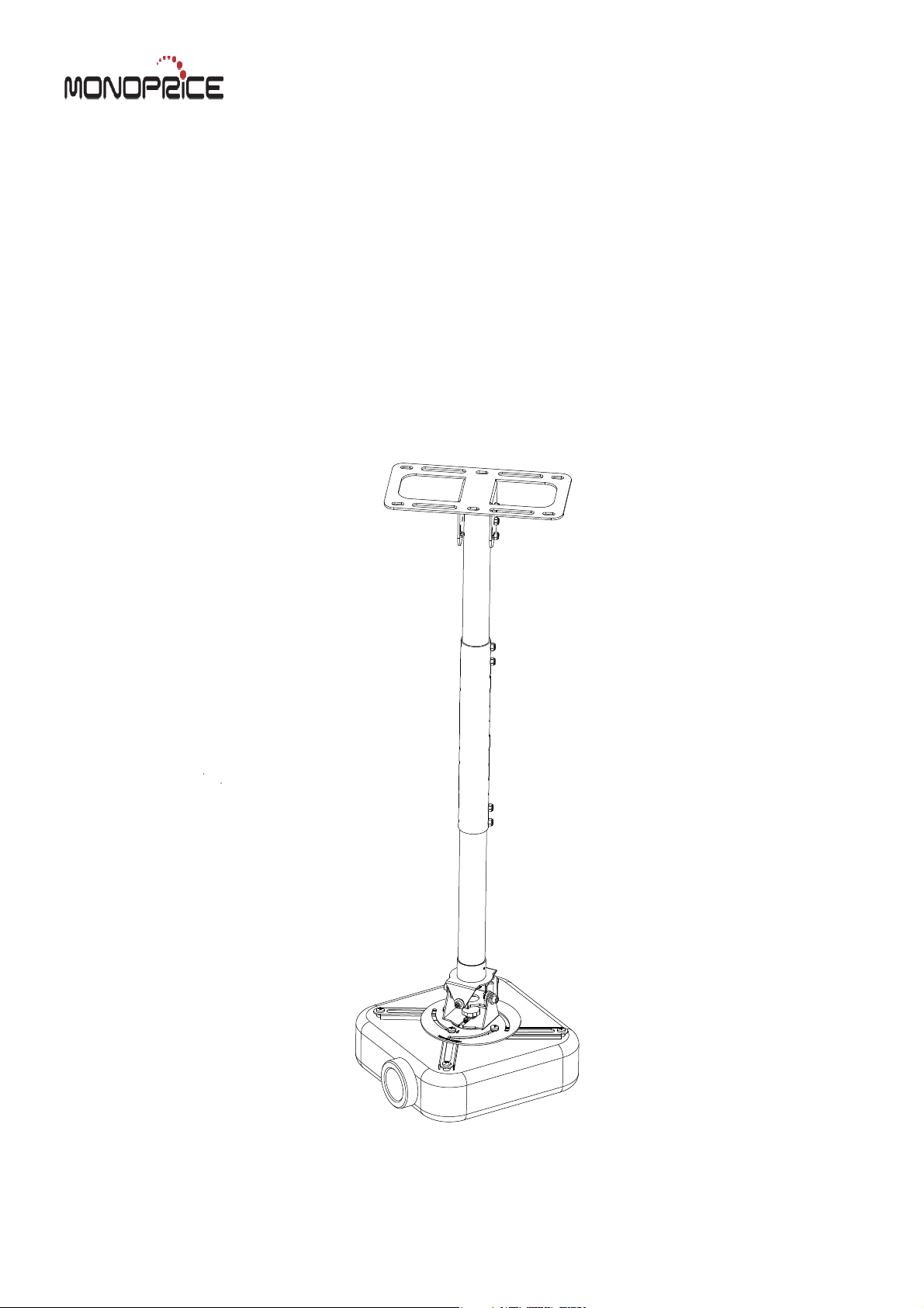
Ceiling Projector mount
MHP-100
Max Load Capacity: 50 lbs (23kg)
Page 2
Note: Read entire instruction sheet before you start installation and assembly.
WARNING
Be sure to read this entire manual thoroughly and you fully understand all the instructions and warning before
attempting to begin your installation.
This product should only be installed by someone who has a basic knowledge of buiding construction,in stallations
and fully understands these instructions.
Make sure that the supporting surface will safely support the combined load of the mount, the display and all
attached hardware and components.
The maximum load capacity is 50 pounds.
Always have someone assist you to lift and position your equipment.
Tighten screws and bolts firmly, but do not over tighten. Over tightening can damage the items and greatly reduce
their ability to hold. Please refer to suggested torque values where applicable in these instructions.
Tools Needed for Assembly
stud finder ("edge to edge" stud finder is recommended)
phillips screwdriver
drill with 1/4", 3/8" drill bits
Table of Contents
Parts List .............................................................................................................................................................................. 3
Installation to Wood Joist Ceiling .......................................................................................................................................... 4
Installation to Concrete Ceiling ............................................................................................................................................. 5
Installation of Extension Column ........................................................................................................................................... 6
Removing the ceiling plate from the flush mount assembly ............................................................................................. 7
Put out columns and install them to the projector .................................................................
Install the bottom plate with projectto ceiling plate .................................................................
Angie adjustment and management .......... .......... .................................................................
............................................. 7
............................................. 8
............................................. 8
2 of 8
Page 3
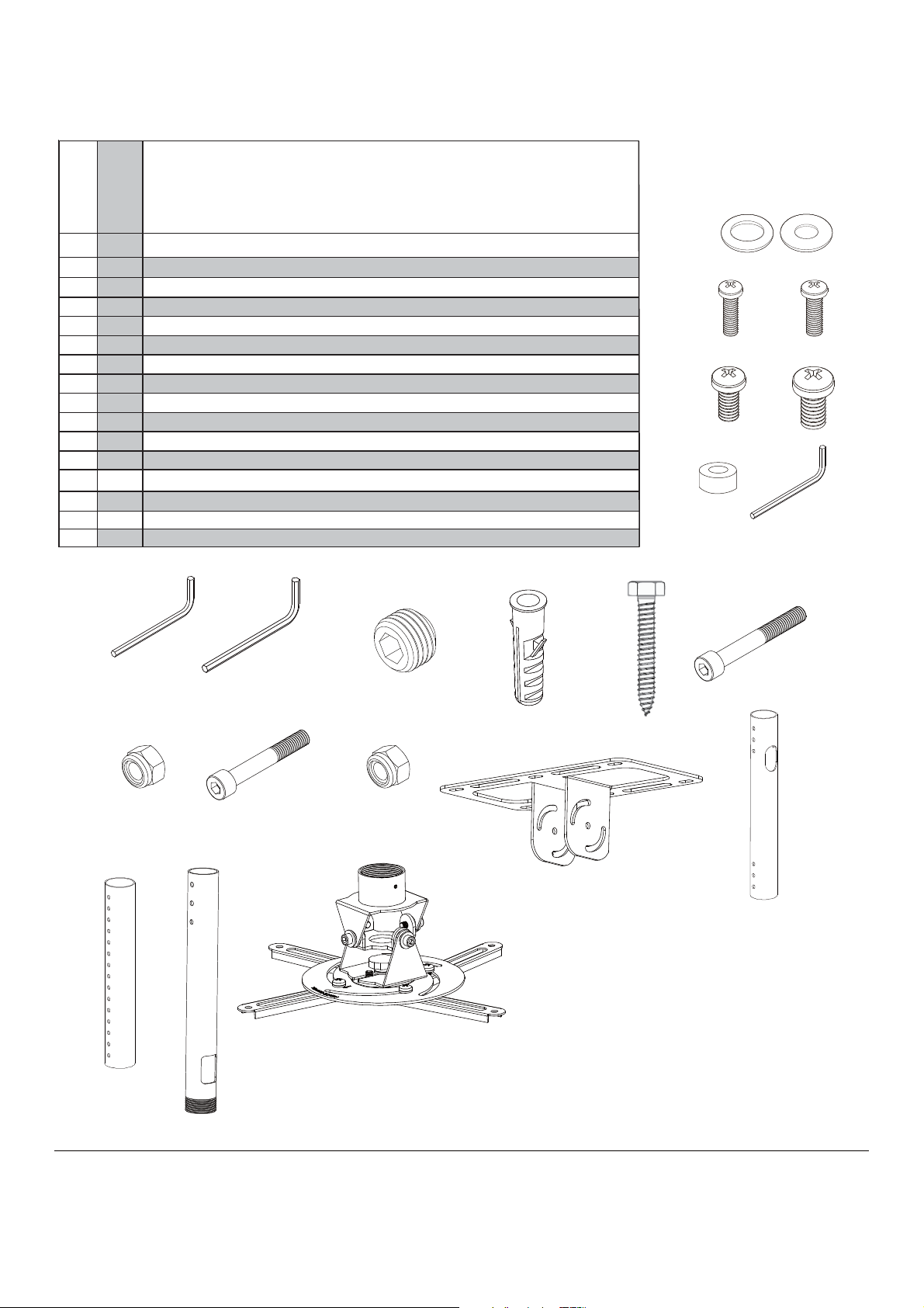
Before you begin, make sure all parts shown are included
with your product.
Parts may appear slightly different than illus trated.
Parts List
Des cription
A
B
C
D
E
F
G
H
J
K
M
M
N
N
washer washer
philips pan head screw
philips pan head screw
philips pan head screw
philips pan head screw
spacer
allen wrench
allen wrench
allen wrench
I
allen cap screw
concrete anchor
hex bolt screw
L
Hexagon fillister head screw
nonskid nut
Hexagon fillister head screw
nonskid nut
4
Ø8.2x16x1.5 Ø8.2x10x1.0
4
4
4
4
4
1
1
1
1
4
4
3
3
4
4
M3x15
M4x15
M5x15
M6x15
Ø6.2x19x7.0
M2.0
M5
M6
M4x3
M8x50
M8x50
M6x60
M6
M6x55
M6
A
B
D
C
E
FG
HIJKL
M
N N plate(x1)
M
AA
EE
BB CC DD
3 of 8
Page 4

Installation to Wood Joist Finished Ceilings,
Exposed Wood Joists, or Wood Beam Ceilings
Drill four 1/4" (6 mm) dia. holes to a minimum
depth of 1.57" (40 mm). Attach ceiling plate (EE)
with four hex bolt screws M8x50 ( L ) as shown
using 1/2" (13mm) socket wrench.Tighten wood
screws ( L ). so ceiling plate
(EE) is firmly attached.
WARNING
Tighten wood screws so that ceiling plate is firmly
attached, but do not overtighten. Overtightening can
damage the screws, greatly reducing their holding
power.
Make sure that mounting screws are anchored into the
center of the joist. The use of an "edge to edge" stud
finder is highly recommended.
WOOD
JOIST
EE
L
4 of 8
Page 5

Installation to Concrete Ceilings
Drill four 3/8" (10 mm) dia. holes to a minimum depth of
1.57" (40 mm). Attach ceiling plate (EE) using four
concrete anchors (K) and M8x50 wood screws ( L
as shown in Illustration A and 1, 2, and 3 (below).
Tighten all fasteners.
)
CONCRETE CEILING
K
WARNING
Tighten wood screws firmly, but do not overtighten.
Overtightening can damage the bolt, greatly reducing
its holding power.
WARNING
Concrete anchors are not intended for attachment to
concrete wall covered with a layer of plaster, drywall,
or other finishing material. If mounting to concrete wall
covered with plaster/drywall is unavoidable, plaster/
drywall (up to 5/8" thick) must be counterbored as
shown below. If plaster/drywall is thicker than 5/8",
custom fasteners must be supplied by installer.
metal
bracket
INCORRECT
concrete
metal
bracket
CORRECT
concrete
EE
L
Illustration A
1
concrete
ceiling
K
Drill hole and insert anchor
2
L
Place ceiling plate over anchor and secure with screw
3
K
CUTAWAY VIEW
plaster/
dry wall
plaster/
dry wall
5 of 8
L
After repeating step one tighten all fasteners
K
Page 6

Installation of Extension Column
Insert and tighten three
M6 x 60mm hexagon fillister head screws (M) to lock
adjuster tube (AA) to ceiling plate (EE) and lock it
by nut (M).
WARNING
Installer must verify that the ceiling will safely support
the combined weight of all attached equipment and
hardware.
Slide extension pipe (BB) over adjuster tube (AA)
to the desired height. Attach with two M6 x 55 mm
hexagon fillister head screws (
Slide extension pipe (CC ) over adjuster tube (BB)
to the desired height. Attach with two M6 x 55 mm
hexagon fillister head screws (N) and lock nut (N).
N) and lock nut (
N ).
EE
M
M
AA
N
BB
N
6 of 8
CC
Page 7

Removing the ceiling plate from the flush
mount assembly
Thumb tightening knob
Spider-plate
NOTE: loosen Thumb knob and
slide spider-plate from ceiling
mount.
Pull out extension columns and install them to the projector
5
Loosen screws on spider arms.
Place the Bottom Spacers in
between the Extension Brackets
and the Projector, and align the
mounting.
NOTE: Adjust spider arms to
4 mounting holes, install screws
and firmly tighten. Be sure to
maintain center
balance point.
7 of 8
Page 8

Install the bottom plate with projector to ceiling plate
6
CC
J
DD
knobs.
Insert and tighten one M4 x 3mm allen cap
screw (J) to lock adjuster tube (CC) to ceiling
plate (DD) .
Aim projector with slot on spider plate
Angie Adjustment and Wire Management
7
M5
±30º
Use knobs for fine adjustment
Pull cables up and through conduit
8 of 8
 Loading...