

Page 1
INSTALLATION GUIDE
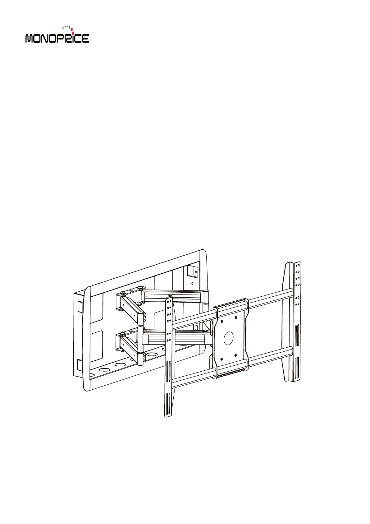
Embedded TV Wall Mount
MHAI-700
Support 42" to 63" Screens
Max Load Capacity: 200 lbs (91 kg)
VESA 500x800 compatible
Page 2
Note: Read entire instruction sheet before you start installation and assembly.
WARNING
Be sure to read this entire manual thoroughly and you fully understand all the instructions and warning before
attempting to begin your installation.
This product should only be installed by someone who has a basic knowledge of buiding construction,in stallations
and fully understands these instructions.
Make sure that the supporting surface will safely support the combined load of the mount, the display and all
attached hardware and components.
The maximum load capacity is 200 pounds.
If mounting to a wall of wood stud construction, be sure that mounting bolts are anchored to the center of the
studs.
Always have someone assist you to lift and position your equipment.
Tighten screws and bolts firmly, but do not over tighten. Over tightening can damage the items and greatly reduce
their ability to hold. Please refer to suggested torque values where applicable in these instructions.
Tools Needed for Assembly
stud finder ("edge to edge" stud finder is recommended)
phillips screwdriver
pencil
drill
1/4"(6mm) drill bit for wood studs
level
tape measure
Table of Contents
Parts List .......................................................................................................................................................................... 3
Installation of Wood Stud Wall
Installing AA to Wood Stud Wall
Mounting the Assembly Adapter Plate to screen
Attach Assembly Adapter Plate to Assembly Arm
Tilt Adjustment and Cord Covers
..........................................................................................
................................................................................
....................................................................................
...............................................................................................................
...............................................................................................................
2 of 8
.............................................. 7
.............................................. 7
......................................... 4
.................................... 5
6
Page 3
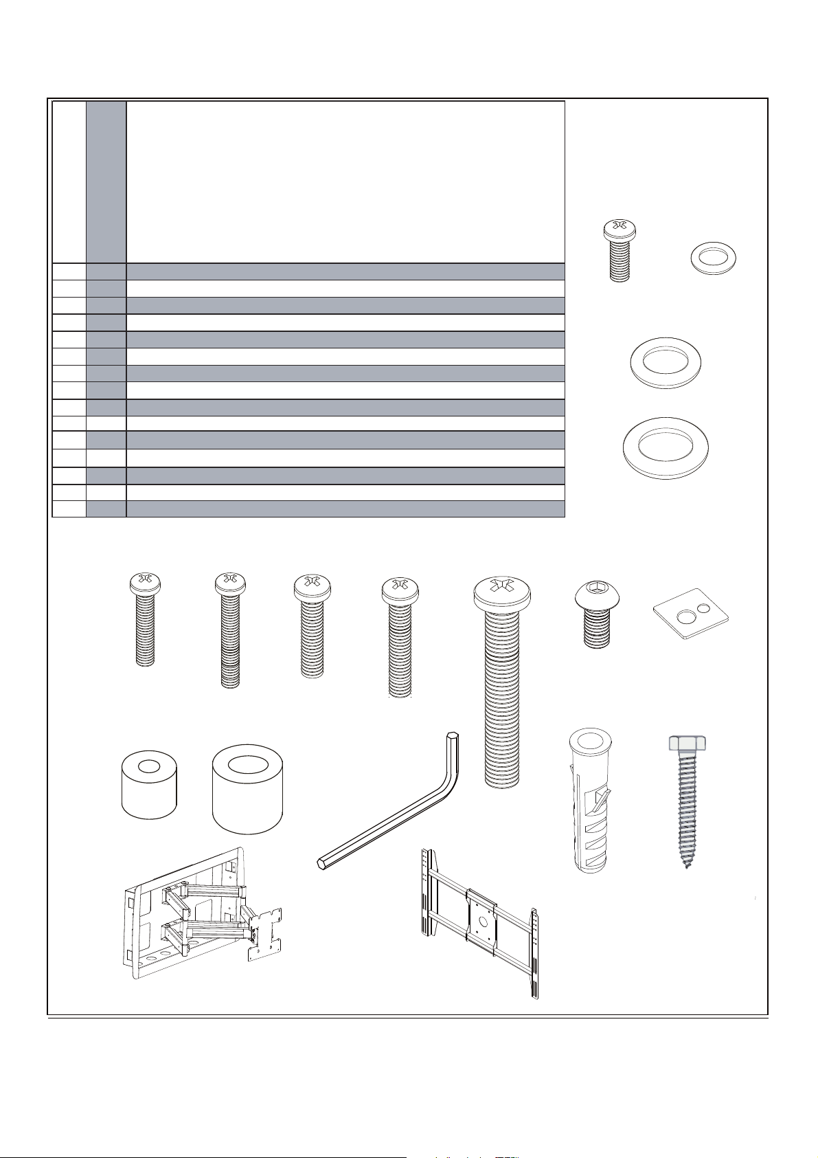
Before you begin, make sure all parts shown are included
with your product.
Parts may appear slightly different than illustrated.
A
B
C
D
E
F
G
H
I
J
K
L
M
N
AA
D
Parts List
Des cription
philips pan head screw . washer
washer
washer
philips pan head screw
philips pan head screw
philips pan head screw
philips pan head screw
philips pan head screw
Inside hexagon socket headcap screw
Square spacer
spacer(1) spacer(2)
wrench
concrete anchor
hexagonal
mount
4
Ø19xØ8.2x19.6 . Ø12.7xØ6.0x12.7
M6x12 . Ø6xØ13x1.2
4
4
6
4
4
4
4
4
4
4
1
6
6
1
Ø8.2xØ1.5x16
Ø8.2xØ2.0x16
M5x16
M5x30
M6x16
M6x30
M8x45
M8x15
25.65x25.65x2.5
M5
M8x50
M8x70
A
B
C
EFG H I J
12
AA
NMLK
Adapter
3 of 7
Page 4

Installation of Wood Stud Wall
In-wall box (BB) can be installed between two studs 16" off center. Use a stud finder to locate the edges of the stud.
A
Use of an edge-to-edge stud finder is highly recommended. Based on its edges, draw vertical lines down the inside
edges of stud’s. Mark desired center of screen between studs. Draw a horizontal line above desired center of screen
as indicated in figure A.1 Draw a second horizontal line 15.1" (383 mm) below this line to outline wall
opening between inside edges of studs. Remove drywall inside cut outline.
Screen center with models
MHAI700:
Center of adapter plate will be
located 7.6" (192 mm) below the
top cut line.
Note: Center of adapter plate
may not represent screen center.
Placement of in-wall box will
depend on the screen center and
location of screen mounting
holes in relation to adapter plate.
CENTER OF
ADAPTER PLATE
CENTER OF
ADAPTER PLATE
fig. A.1
30.4"
(771 mm)
TOP CUT LINE
Installation of Wood Stud Wall (continued)
WARNING
hardware and components.
screws, greatly reducing their holding power.
highly recommended.
are responsible to provide hardware for other types of mounting situations.
A-1
Insert (AA) into cut-out. Level AA, and mark the center of the six mounting holes.
Make sure AA is level, secure it using
as shown in figure A-1.1
six M8X70(N)
hexagonal screws
4 of 7
Page 5

NOTE
When inset AA into Wood Stud Wall ,mark installed holes with pen ,as picture A-1.1 After finishing above
process take out AA . Drill is six 1/4"(6mm) dia. holes are 3"(60mm) deep.
AA
figA-1.1
Installing AA to Wood Stud Wall
Insert AA into wall again, install washer (C) in marked holes,Make sure
B
AA is level.This process must be done two or more people.
Install AA into wall as shown in figure B.1 Make sure AA
is level.Fix them with six M8x70 (N)
hexagonal screws.as shown in figure B.1
N
C
5 of 7
figB.1
Page 6

C
Mounting the Assembly Adapter Plate to screen
Modify the Adapter Plate
Adaptor Modify the Assembled Adapter Plate
Slide the adapter brackets into Assembled adapter plate slightly.
Place the Assembled Adapter Plate on the back of the display with
one Adapter Bracket aligned with a set of vertical mounting
holes.Then,slide the other Adapter Bracket in or out until it aligns
with the second set of vertical mounting holes.The Adapter should
be horizontally centered on the back of the flat panel display.
Adapter
Bracket
Adaptor and hooks
and tighten it with
D E F G or H
Use four M6x12 screws (A)and four iron spacers(A)
Phillips Head Screw Driver.
Square
Washer(J)
Top of
Display
For screen with a hole
pattern in a pocket spacers
go between Assembl y
Adapter Plate and screen
Mounting
Screw
MM
Washer Hole
Metal Washer
x
x
Mx
Screw
Note:
Recessed Mounting Holes.
If the mounting holes are recessed
into the back of the display, use the
supplied spacers to pack the
recessed hole. If the mounting
screw is M5&M6,use the
Spacers1.(K.1.)If the mounting screw
is M8,use the Spacers 2.(K.2.)
Ensure that the brackets are
securely fixed to the display.
Spacers
6 of 7
Page 7

Attach Assembly Adapter Plate to Assembly Arm
D
( B )
Iron spacer
( I )
M8x15mm
screw bolt
.25"
top screw
1. Insert two M8x15mm screws bolt
and two metal washers into swivel box
on Assembly Adapter Plate as above
shown.
Leave approx. 1/4" of exposed thread.
2. Lift the display and hook it
over the mounting head by lowering
the exposed portion of the top screws
down the open key slots.
( B )
Tighten
Iron spacer
Loosen
( I )
M8x15mm
screw bolt
WARNING:
Before removing
display,ensure
the display has a
negative Tilt and
Tilt Lever is
LOCKED!
your
NOTE:This procedure will require
two persons.Ensure that the arm is
set to its maximum negative tilt prior
to attaching the display
Tilt Adjustment
E E
1.Loosen Tiltlevers(Only enough to
allow controlled adjustment)
2. Adjust Tilt
3. Lock Tilt Levers(Tighten)
4. Once Tilt Levers are locked,the
position of the levers can be adjusted
without loosening ortightening the unit
by pulling the levers outwards and then
repositioning them to a vertical,less
obtrusive position.
Tiltlever
3. Once in position, attach the bottom
two M8x15mm screws and two Iron
washers to secure the display to the
mounting head using M5mm Allen
Wrench.
Cord Covers
Install Cord Covers as shown.
Cord Covers
NOTE:Be sure to leave enough
slack to allow for movement of
the arms.
7 of 7
 Loading...