

Page 1
INSTALLATION GUIDE
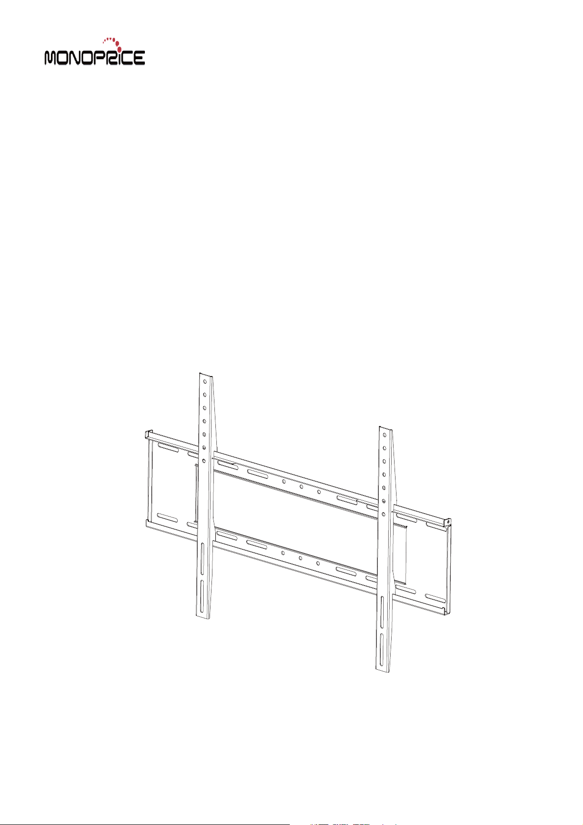
Flat Panel Mount
MF- 63
Support 37" to 63" Screens
Max Load Capacity: 200 lbs (91 kg)
VESA 200x200 / 400x500 / 500x800 compatible
Page 2
Installation Instructions
Model Name:MF-63
37”-63”UNIVERSAL FIXED WALL MOUNT
Important Notes
The37”-63”Universal Fixed Wall Mount supports LCD and flat panel displays from 37"(81cm) to
63"(132cm) and supports a maximum load of 91 kg(200 lbs).
The manufacturer does not accept responsibility for incorrect installation.
Component Checklist
Bits Bag
C
8.2X1.5X 16
iron spacer(x4)
J
square spacer (x4)
K
12.7X 6.0X12.7
Spacer(x4)
Wall Plate
TOOLS REQUIRED:
Power Drill
10mm or 6mm Drill Bit
Phillips Head Screw Driver
Spirit Level
13mm (
1
) Socket Wrench
2
/
or Shifter
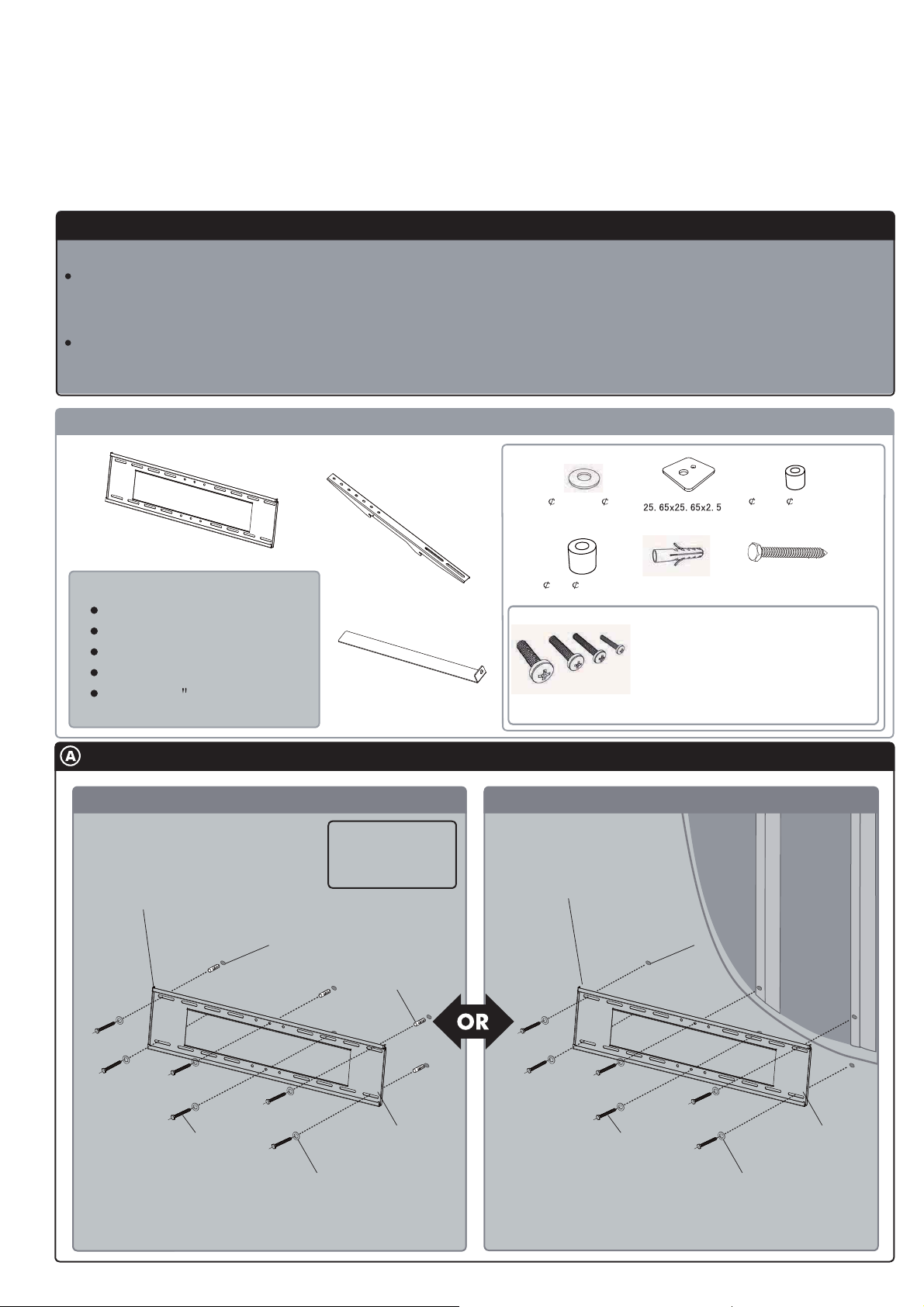
Mounting the Wall Plate
Masonry Wall
Note:Ensure the Wall Plate
is mounted with the folded
tabs pointing upwards.
3
10mm(
/8”) Hole
monitor bracket-(BB)
Security Bracket
TIP:Use a spirit
level to ensure the
Wall Plate is
horizontal
concrete anchor
L
19X 8.2X19.6
Spacer(x4)
Cross pan head screw
MN
concrete anchor outside the hexagonal
M8x mm
M8x mm
M6x mm
M6x mm
M5x35
M5x16mm
Timber Stud Wall
Note:Ensure the Wall Plate
is mounted with the folded
tabs pointing upwards.
10mm(
M8X50(
35
16
35
16
x6)
self-tapping screws(X6)
mm
3
/8”) Hole
M8
X70
(x4 each)
(x4 each)
(x4 each)
(x4 each)
((xx4each)
4each)
I
H
G
F
E
D
outside the hexagonal
self-tapping screws
iron spacer
Wall Plate
outside the hexagonal
self-tapping screws
Wall Plate
iron spacer
Page 3

Mounting the Display Brackets
Mounting
screw
square spacer
Adapter
Bracket
M6 & M8
Screw hole
M4 & M5
Screw Hole
NOTE:
*
When attaching the mounting
screws to the display,make sure
the direction of Brackets is correct
and ensure that both brackets
are vertically aligned.
Recessed Mounting Holes.
If the mounting holes are recessed
into the back of the display, use the
supplied spacers to pack the recessed
hole. If the mounting screw is M4
& M5 & M6,use the ¢ 1 2.7 x¢ 6 . 0 x 12 .7
Spacer.If the mounting screw is M8,use
the ¢19x¢8.0x19.4 Spacer . Ensure
that the brackets are securely fixed to
the display.
Mounting
screw
square spacer
Bracket
Attaching the display to the wall plate
Note: This procedure will
require two persons
With the Brackets attached
to the display, lift the
display and hook the
brackets onto the Wall
Plate as shown.
Note: For demonstration purposes, the wall
has been omitted from the above images.
Security Option
Note: For demonstration purposes, the wall
has been omitted from the above images.
Back
of Display
Recessed
ole
H
Spacer
Back plate
Padlock
Security
Bracket
For additional security, it is suggested that the left and
right Security Brackets be inserted and a Padlock attached
through each Security Bracket and the Wall Plate as shown.
The two Padlocks (not supplied) should have a shackle
diameter no larger than 5mm(
/16”).
3
 Loading...