

Page 1
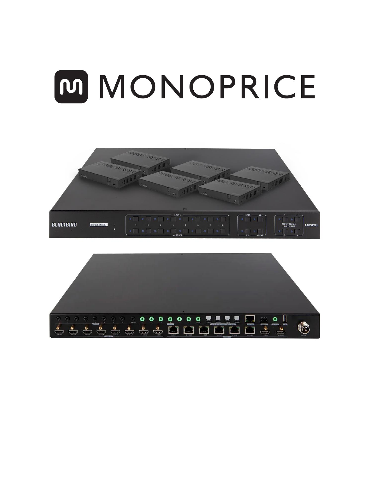
Blackbird™ 4K 8x8 HDBaseT™ Matrix with 6 Receivers
P/N 39670
User's Manual
Page 2

2
CONTENTS
SAFETY WARNINGS AND GUIDELINES ................................................................................................................................... 4
INTRODUCTION .......................................................................................................................................................................................... 5
FEATURES ........................................................................................................................................................................................................ 6
CUSTOMER SERVICE .............................................................................................................................................................................. 6
PACKAGE CONTENTS ............................................................................................................................................................................ 7
PRODUCT OVERVIEW ........................................................................................................................................................................... 8
Matrix Front Panel ............................................................................................................................................................................................................................ 8
Matrix Rear Panel ............................................................................................................................................................................................................................... 9
Receiver ....................................................................................................................................................................................................................................................10
IR Remote Control ........................................................................................................................................................................................................................... 12
SAMPLE CONNECTION DIAGRAM ............................................................................................................................................ 13
IR PASS-THROUGH CONTROL ...................................................................................................................................................... 14
Controlling a Single Remote Display from the Matrix .....................................................................................................................................14
Controlling All Remote Displays from the Matrix ................................................................................................................................................ 15
Controlling a Single Source Device from a Receiver ......................................................................................................................................... 16
Controlling All Source Devices from All Receivers .............................................................................................................................................. 17
CONTROL ....................................................................................................................................................................................................... 18
Front Panel Buttons .......................................................................................................................................................................................................................18
IR Remote Control ........................................................................................................................................................................................................................... 19
WEB GUI CONTROL .............................................................................................................................................................................. 20
Login ......................................................................................................................................................................................................................................................... 20
Switching Tab ...................................................................................................................................................................................................................................... 21
Audio Tab ............................................................................................................................................................................................................................................... 22
Configuration Tab ........................................................................................................................................................................................................................... 23
CEC Tab .................................................................................................................................................................................................................................................... 26
RS232 Tab ...............................................................................................................................................................................................................................................28
Page 3

3
Interface Tab ....................................................................................................................................................................................................................................... 30
Network Tab ......................................................................................................................................................................................................................................... 31
Access Tab ............................................................................................................................................................................................................................................ 32
WEB GUI UPGRADE...............................................................................................................................................................................33
RS-232 CONNECTION ......................................................................................................................................................................... 34
Controlling the Matrix with a PC Connected to the Matrix ....................................................................................................................... 34
Controlling the Matrix with a PC Connected to a Receiver ....................................................................................................................... 35
Controlling a Remote Third-Party Device with a PC Connected to the Matrix ........................................................................ 36
Control a Local Third-Party Device with a PC Connected to a Receiver ........................................................................................ 37
RS-232 CONTROL ................................................................................................................................................................................... 38
RS-232 COMMANDS ........................................................................................................................................................................... 39
System Settings ............................................................................................................................................................................................................................... 39
Signal Switching ............................................................................................................................................................................................................................. 46
Audio Settings .................................................................................................................................................................................................................................. 49
EDID Management ........................................................................................................................................................................................................................ 50
HDCP Management....................................................................................................................................................................................................................... 53
Third-Party Device Control ..................................................................................................................................................................................................... 55
CEC Control ......................................................................................................................................................................................................................................... 58
FIRMWARE UPGRADE ......................................................................................................................................................................... 61
TROUBLESHOOTING ............................................................................................................................................................................ 62
TECHNICAL SUPPORT ......................................................................................................................................................................... 63
SPECIFICATIONS ..................................................................................................................................................................................... 63
Matrix ........................................................................................................................................................................................................................................................ 63
Receivers ................................................................................................................................................................................................................................................65
REGULATORY COMPLIANCE ........................................................................................................................................................ 66
Notice for FCC .................................................................................................................................................................................................................................. 66
Notice for Industry Canada .................................................................................................................................................................................................... 67
Page 4

4
SAFETY WARNINGS AND GUIDELINES
Please read this entire manual before using this device, paying extra attention to these
safety warnings and guidelines. Please keep this manual in a safe place for future reference.
• This device is intended for indoor use only.
• Do not expose this device to water or moisture of any kind. Do not place drinks or
other containers with moisture on or near the device. If moisture does get in or on
the device, immediately unplug it from the power outlet and allow it to fully dry
before reapplying power.
• Do not touch the device, the power cord, or any other connected cables with wet
hands.
• Do not expose this device to excessively high temperatures. Do not place it in, on,
or near a heat source, such as a fireplace, stove, radiator, etc. Do not leave it in
direct sunlight.
• Use only in a well-ventilated area. Do not use in close, confined spaces.
• Prior to operation, check the unit and power cord for physical damage. Do not use if
physical damage has occurred.
• Before plugging the unit into a power outlet, ensure that the outlet provides the
same type and level of power required by the device.
• Unplug this device from the power source when not in use.
• Take care to prevent damage to the power cord. Do not allow it to become
crimped, pinched, walked on, or become tangled with other cords. Ensure that the
power cord does not present a tripping hazard.
• Never unplug the unit by pulling on the power cord. Always grasp the connector
head or adapter body.
• Ensure that power is turned off and disconnected before making any electrical
connections.
• Remove the batteries from the controller if it will go unused for a lengthy period of
time.
Page 5

5
• Clean using a soft, dry cloth only. Do not use chemical cleaners, solvents, or
detergents. For stubborn deposits, moisten the cloth with warm water.
• This device has no user serviceable parts. Do not attempt to open, service, or
modify this device.
INTRODUCTION
This Blackbird™ 4K 8x8 HDBaseT™ Matrix features 8 HDMI® inputs, 2 HDMI outputs, 6
HDBaseT outputs, and 4 digital optical S/PDIF audio outputs. It supports video resolutions
up to 4K@60Hz with YCbCr 4:4:4 and can transmit 4K video to distances up to 131 feet (40
meters) and 1080p video to distances up to 229 feet (70 meters) over a single Cat5e/6
Ethernet cable. Audio extracted from the HDMI inputs, HDBaseT outputs, and Audio Return
Channel (ARC) output from the HDBaseT receivers can be output using the 4 digital optical
S/PDIF audio connectors. It supports bidirectional IR extension and features front panel
buttons, IR remote control, RS-232, and Web GUI control options. It supports the Power
over Cable (PoC) feature, which allows the receivers to draw their power from the matrix
over the Ethernet cable. It includes smart EDID® management using the 4-pin DIP switch on
the rear panel.
Page 6

6
FEATURES
• Supports HDMI® resolutions up to 4K@60Hz with YCbCr 4:4:4 HDR, including
1080p@60Hz and 3D video
• Fully compliant with the HDMI 2.0 and HDCP™ 2.2 specifications
• Can transmit 4K signals to distances up to 131 feet (40 meters) and 1080p signals to
distances up to 229 feet (70 meters) over a single Cat5e/6 Ethernet cable
• Features 6 HDBaseT™ outputs and includes 6 receivers
• Supports the 24V Power over Cable (PoC) feature, allowing the receivers to draw
their power from the matrix over the Ethernet cable
• Includes two HDMI outputs for connecting local displays
• Audio from the HDMI inputs, HDBaseT and HDMI outputs, and Audio Return
Channel (ARC) audio from the receivers can be output to 4 digital optical S/PDIF
audio outputs
• Includes smart EDID® management using the 4-pin DIP switch on the rear panel
• Can be controlled using the front panel controls, the included IR remote control, or
with a computer using an RS-232 or Ethernet connection
CUSTOMER SERVICE
The Monoprice Customer Service department is dedicated to ensuring that your ordering,
purchasing, and delivery experience is second to none. If you have any problem with your
order, please give us an opportunity to make it right. You can contact a Monoprice
Customer Service representative through the Live Chat link on our website
www.monoprice.com or via email at support@monoprice.com. Check the website for
support times and links.
Page 7

7
PACKAGE CONTENTS
Please take an inventory of the package contents to ensure you have all the items listed
below. If anything is missing or damaged, please contact Monoprice Customer Service for a
replacement.
1x Blackbird™ 4K 8x8 HDBaseT™ matrix
6x HDBaseT receivers
2x Mounting ears with 6 screws for the matrix
12x Mounting ears with 24 screws for the receivers
4x Plastic feet for the matrix
24 Plastic feet for the receivers
1x IR remote control
6x IR receivers
8x IR transmitters
1x RS-232 cable (3-pin to DB-9)
6x 3-pin terminal blocks
1x AC power adapter
1x User's manual
Page 8
8
PRODUCT OVERVIEW
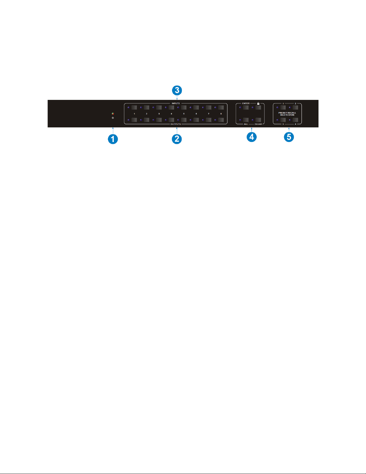
Matrix Front Panel
1. POWER LED: The LED indicator illuminates red when power is applied.
2. OUTPUTS: Eight buttons with LED indicators for selecting the outputs.
3. INPUTS: Eight buttons with LED indicators for selecting the inputs.
4. MENU: Four buttons for performing various menu related functions.
• ENTER: Press the button to accept the changes.
• LOCK: Press the button to lock or unlock the other buttons on the front panel.
• ALL: Press the button to select all inputs for EDID® management or all outputs
for switching.
• CLEAR: Press the button to cancel pending changes.
5. PRESET RECALL: Momentarily press one of the 4 buttons to select a previously
saved preset. The LED to the left of the button illuminates to indicate that the
preset is active. Press and hold one of the 4 buttons to save the current input
selections for each output channel to a preset.
Page 9

9
Matrix Rear Panel
1. INPUTS: Eight HDMI® inputs for connecting the video source devices.
2. OUTPUTS:
• 1-6 HDBT: Six RJ45 Ethernet jacks for connecting the included receivers using
Cat5e/6 Ethernet cables (not included).
• 7-8 HDMI: Two HDMI output ports for connecting local displays.
3. IR OUT:
• 1-8: Eight 3.5mm jacks for connecting the included IR transmitters for IR pass-
through control of the individual video source devices.
• ALL OUT: One 3.5mm jack for connecting one of the included IR transmitters for
IR pass-through control of all video source devices.
4. IR IN:
• 1-6: Six 3.5mm jacks for connecting the included IR receivers to receive IR signals
for transmission to the corresponding HDBaseT™ receivers.
• ALL IN: One 3.5mm jack for connecting one of the included IR receivers to
receive IR signals for transmission to all HDBaseT receivers.
5. AUDIO MATRIX OUTPUTS/ARC: Four digital optical S/PDIF connectors for
connecting external amplifiers for separate amplification of audio de-embedded
from the HDMI inputs, HDBaseT and HDMI outputs, and Audio Return Channel (ARC)
audio from the HDBaseT receivers. By default, the four outputs use audio de-
embedded from HDBaseT receivers 1-4. The source for the audio de-embedding can
be set using the built-in Web GUI or using RS-232 commands.
Page 10
10
6. CONTROL:
• TCP/IP: RJ45 Ethernet jack for connecting to an existing Ethernet network using
a Cat5e/6 Ethernet cable (not included) for computer control using the built-in
Web GUI.
• RS232: 3-pin terminal block for connecting the included RS-232 cable for
computer control using RS-232 commands or to connect to a third-party device
for RS-232 control.
• IR EYE: 3.5mm jack for connecting one of the included IR receivers to control the
matrix using the included IR remote control.
• FW: USB Type-A port for connecting a USB flash drive for performing firmware
updates.
7. DC 12V: Connector for attaching the included AC power adapter.
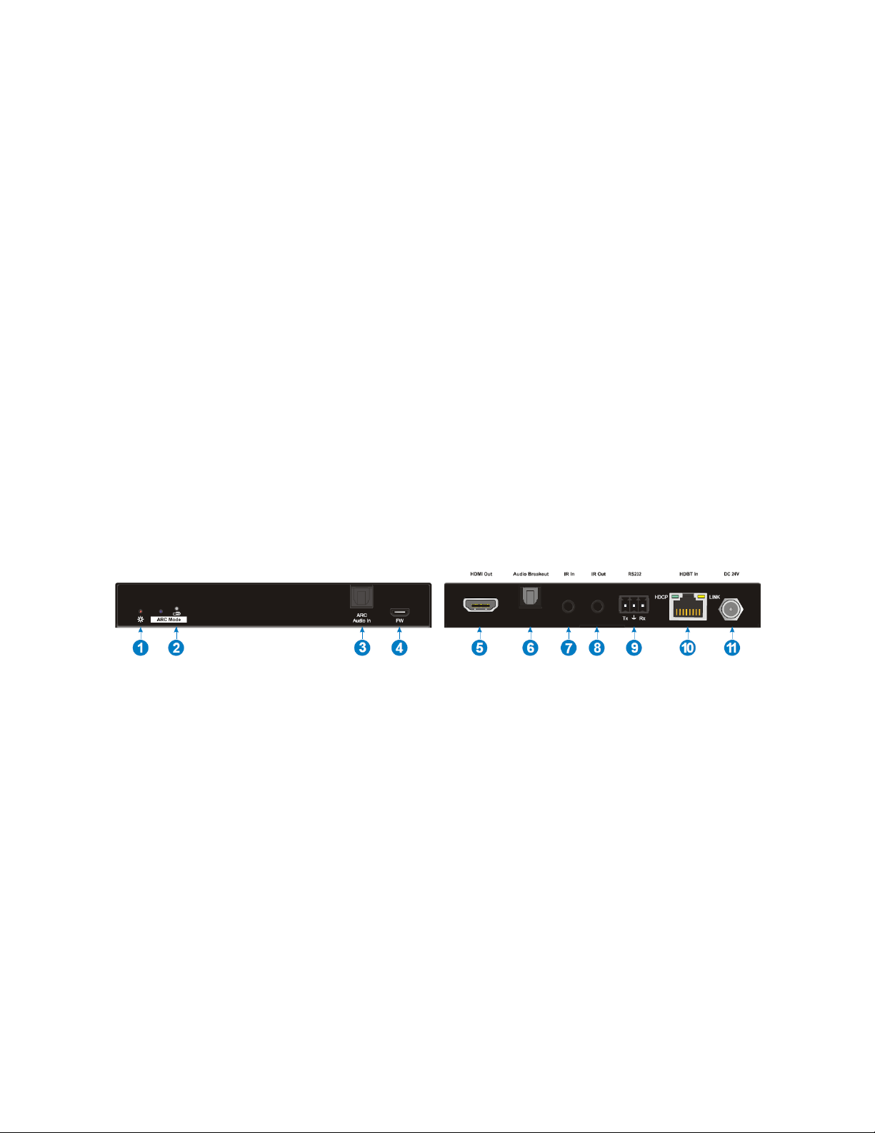
Receiver
1. POWER LED: The LED illuminates red when power is applied.
2. ARC Mode: Use a paper clip or other sharp, thin device to press the recessed button
to enable or disable Audio Return Channel (ARC) audio. When ARC mode is enabled,
the LED illuminates blue. When ARC audio is selected as the audio source for one of
the digital optical S/PDIF outputs on the matrix, ARC mode is automatically enabled.
3. ARC Audio In: Digital optical S/PDIF input for connecting the ARC audio source (e.g.,
TV) using a digital optical S/PDIF audio cable (not included).
4. FW: Micro USB port for connecting a USB flash drive to perform firmware updates.
5. HDMI Out: HDMI® port for connecting an HDMI display using an HDMI cable (not
included).
Page 11

11
6. Audio Breakout: Digital optical S/PDIF connector for connecting an external
amplifier using a digital optical S/PDIF cable (not included) for amplification of
audio de-embedded from the input. Note that if ARC mode is enabled, this output is
disabled.
7. IR In: 3.5mm jack for connecting one of the included IR receivers for IR pass-through
control of the video source devices.
8. IR Out: 3.5mm jack for connecting one of the included IR transmitters for IR pass-
through control of the connected display.
9. RS232: 3-pin terminal block for connecting the included RS-232 cable for computer
control of the matrix using RS-232 commands or to connect to a third-party device
for RS-232 control.
10. HDBT In: RJ45 jack for connecting the Ethernet cable from the matrix. The HDCP LED
illuminates green when the video contains HDCP™ content. The LINK LED
illuminates orange when there is a valid HDBaseT™ link with the matrix.
11. DC 12V: DC barrel connector for connecting an AC power adapter (not included).
Note that the receivers can be power using the Power over Cable (PoC) feature, so
no AC power adapters for the receivers are included.
Page 12

12
IR Remote Control
1. STANDBY: Press the STANDBY button to turn the matrix on
or to put it into standby mode.
2. INPUTS: Eight numbered buttons corresponding to the eight
inputs.
3. OUTPUTS: Eight numbered buttons corresponding to the
eight outputs.
4. MENU:
• ALL: The ALL button can be used to select all INPUTS for
EDID® management or all OUTPUTS for switching.
• EDID: The EDID button is used to set the EDID for one or
more INPUTS to the EDID capabilities of the selected
OUTPUT.
• CLEAR: The CLEAR button is used to cancel a change in
progress.
• ENTER: The ENTER button is used to accept the change.
Page 13
13
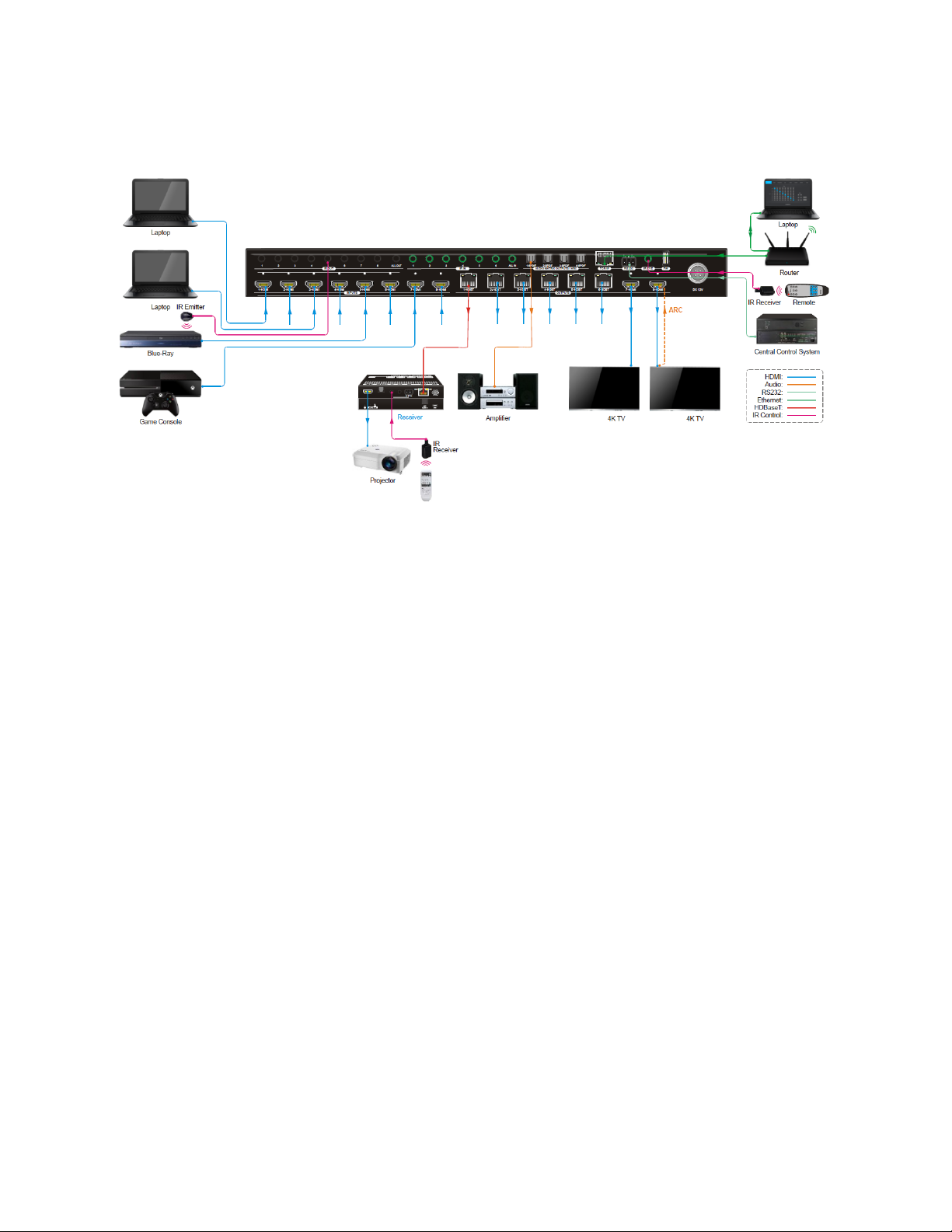
SAMPLE CONNECTION DIAGRAM
Page 14
14
IR PASS-THROUGH CONTROL
This matrix features bidirectional IR control and includes 6 IR receivers and 8 IR
transmitters. The receivers and transmitters can be installed in a variety of ways for several
control options. The following diagrams illustrate the various control methods.
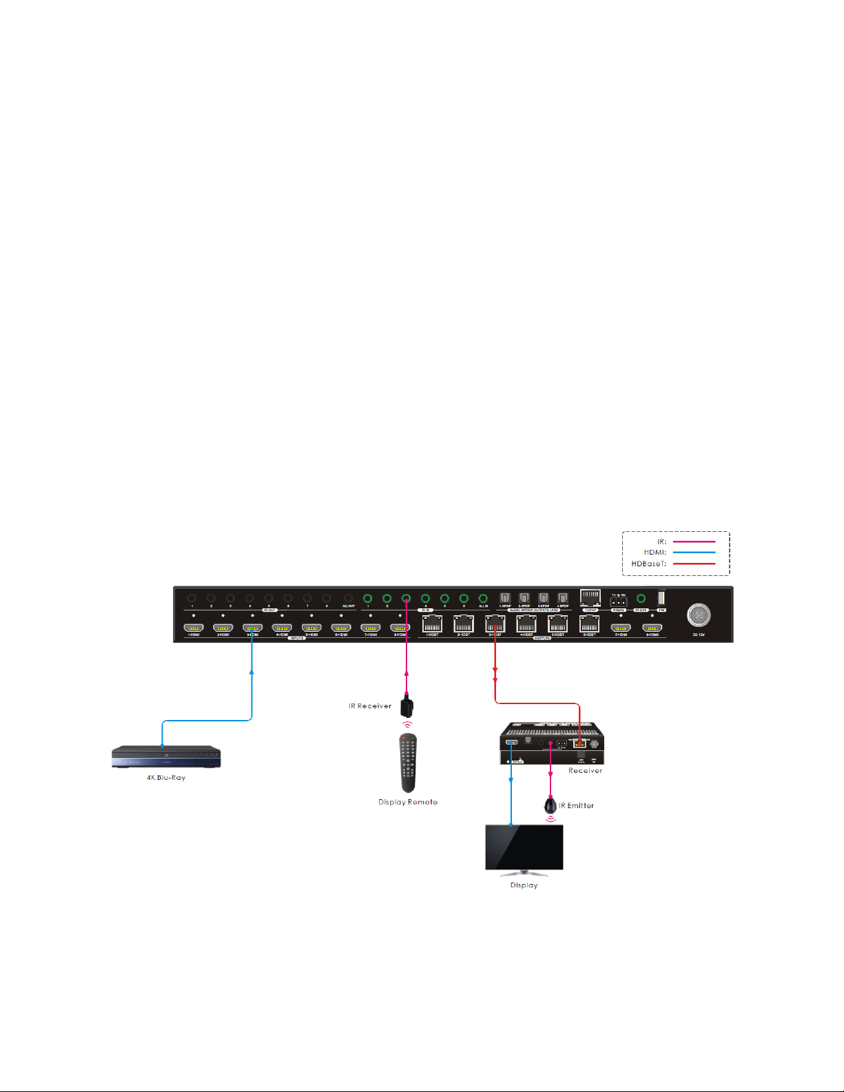
Controlling a Single Remote Display from the Matrix
Perform the following steps to connect for control of one of the remote displays from the
matrix location.
1. Plug one of the included IR transmitters to the IR Out jack on the receiver, then
position the emitter so that it can transmit to the IR eye on the display.
2. Plug one of the included IR receivers to the IR IN jack on the matrix that
corresponds to the receiver, then position it so that it can receive IR signals from
the remote display's IR remote control.
Page 15
15
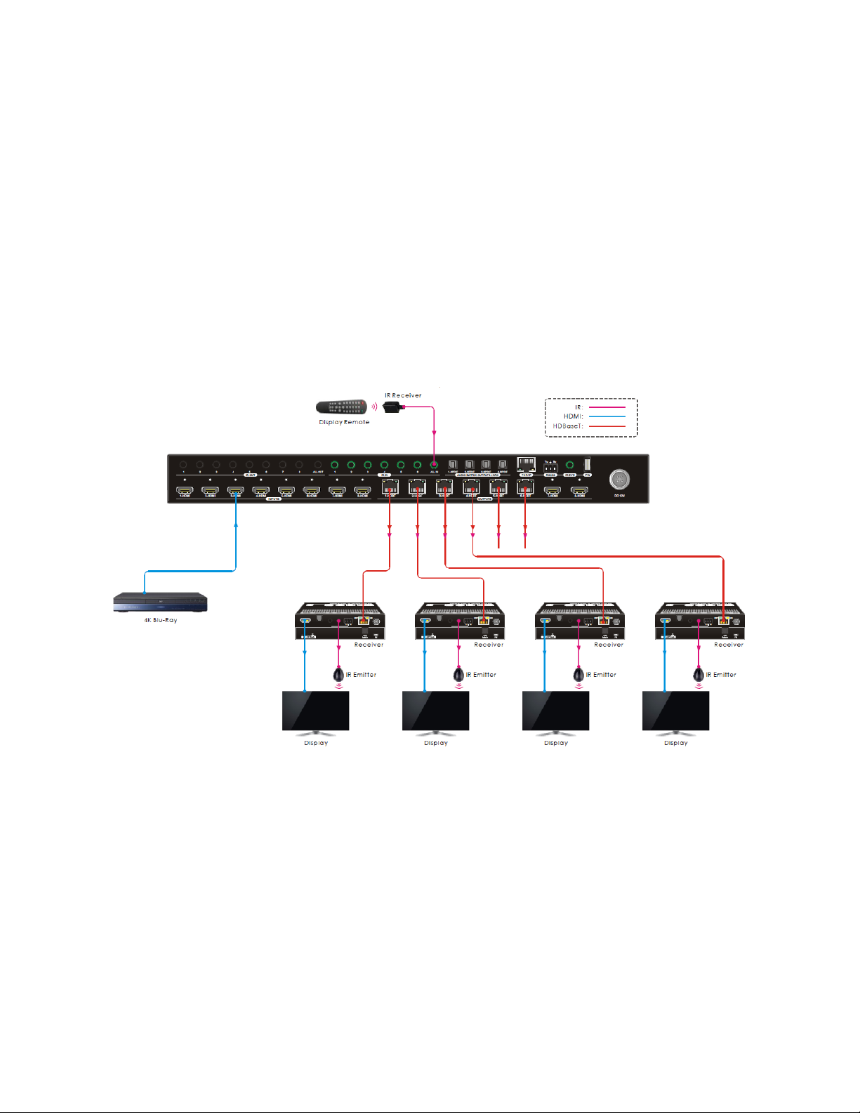
Controlling All Remote Displays from the Matrix
Perform the following steps to connect for control of all of the remote displays from the
matrix location.
1. Plug one of the included IR transmitters to the IR Out jack on each connected
receiver, then position the emitters so they can transmit to the IR eyes on each
display.
2. Plug one of the included IR receivers into the IR IN ALL IN jack on the matrix, then
position it where it can receive IR signals from the remote displays' IR remote
controls.
Page 16
16
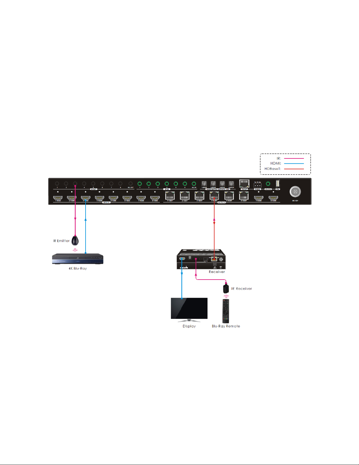
Controlling a Single Source Device from a Receiver
Perform the following steps to connect for control of a single video source device from the
receiver location.
1. Plug one of the included IR transmitters into the IR OUT jack on the matrix that
corresponds to the source device to be controlled, then position it where it can
transmit to the IR eye on the source device.
2. Plug one of the included IR receivers into the IR In jack on one of the receivers, then
position it where it can receive signals from the source device's IR remote control.
Page 17
17
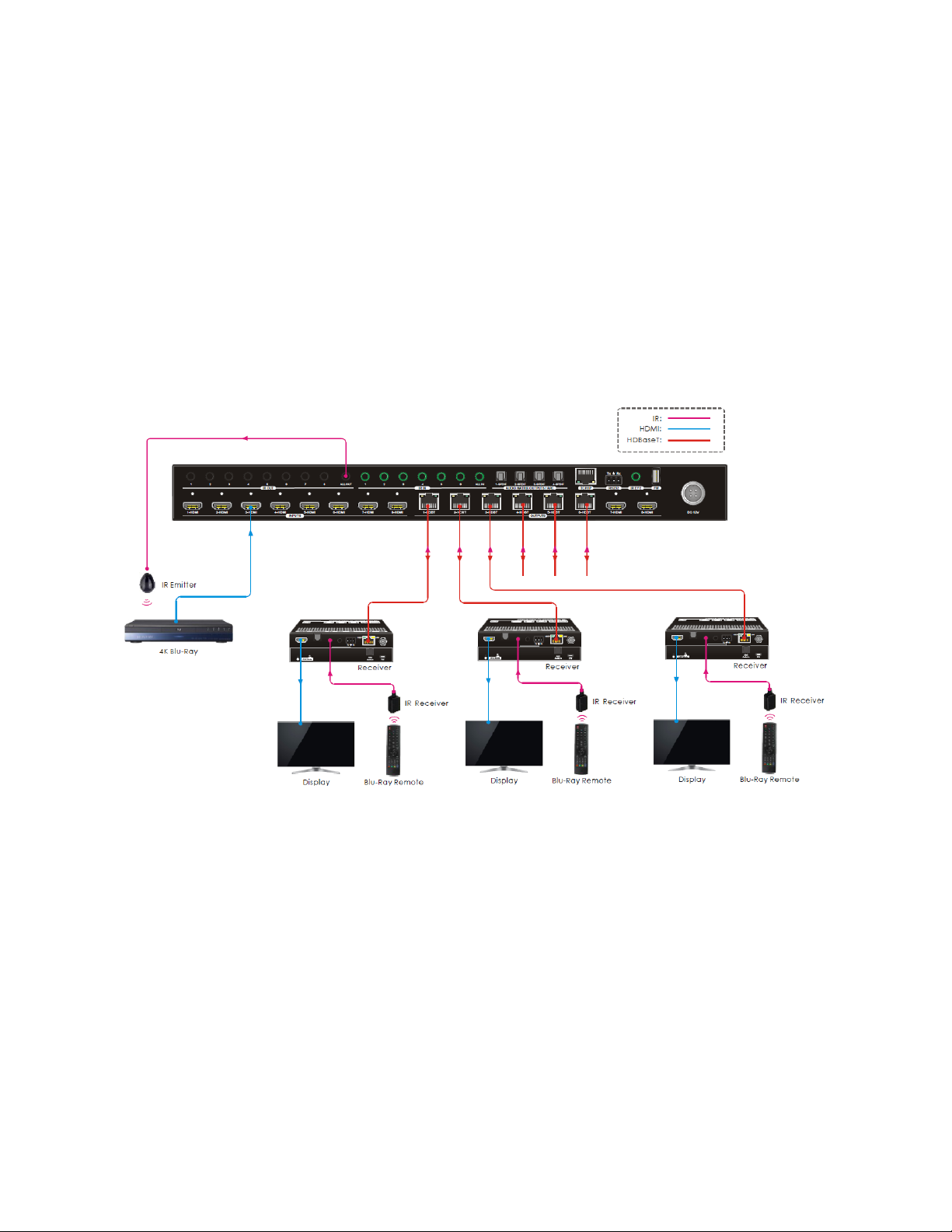
Controlling All Source Devices from All Receivers
Perform the following steps to connect for control of all video source devices from the
receiver locations.
1. Plug one of the included IR transmitters into the IR OUT ALL OUT jack on the matrix,
then position it where it can transmit to the IR eyes on the source devices.
2. Plug one of the included IR receivers into the IR In jack on one or more of the
receivers, then position them where they can receive signals from the source
devices' IR remote controls.
Page 18

18
CONTROL
Front Panel Buttons
The matrix can be controlled using the buttons on the front panel. Whenever a command is
accepted, the LEDs of all buttons pressed will blink three times, then turn off. If the ENTER
or CLEAR button is not pressed after initiating a change, the LEDs will turn off after eight
seconds.
• To switch an input to one or more outputs, press one of the INPUTS buttons, then
press one or more OUTPUTS buttons or the ALL button for all outputs, and finally
press the ENTER button to execute the change.
• To see which input is assigned to a given output, press and hold the OUTPUTS
button you want to query. The LED of the assigned input illuminates blue. The LEDs
turn off when you release the OUTPUTS button.
• Press and hold the LOCK button for about 3 seconds to lock or unlock the other
front panel buttons. The LED next to the LOCK button illuminates blue when the
front panel buttons are locked.
• Press and hold one of the PRESET buttons to save the current switching layout to
the corresponding preset. Momentarily press one of the PRESET buttons to load the
corresponding preset. The LED next to the selected PRESET button illuminates blue
to indicate that it is selected.
Note: The matrix supports nine presets, but only the first four presets can be
accessed using the front panel controls and only the first six can be managed in the
Web GUI. The other three presets can be managed using RS-232 control.
• Press the ENTER button to execute any pending commands.
• Press the CANCEL button to clear any pending commands.
Page 19

19
IR Remote Control
• Press the STANDBY button to turn the matrix on or to put it
into standby mode.
• To switch the selected input for one or more of the outputs,
first press the number button in the INPUTS section
corresponding to the desired input, then press one or more
number buttons in the OUTPUTS section or the ALL button in
the MENU section for all outputs, and finally press the ENTER
button in the MENU section to execute the change.
• To set the EDID® for one or more source devices to the EDID
capabilities of a specific output, press the EDID button, then
press one or more number buttons in the INPUTS section
corresponding to the desired input(s) or the ALL button in
the MENU section for all inputs, then press a number button
corresponding to the OUTPUT with the desired EDID settings,
and finally press the ENTER button in the MENU section to
execute the change.
• At any time prior to pressing the ENTER button to execute
the change, you can press the CANCEL button in the MENU section to cancel the
pending change.
Following are some examples:
• To send input 3 to output 2, first press the INPUTS 3 button, then press the
OUTPUTS 2 button, and finally press the ENTER button to execute the change.
• To send input 4 to all outputs, first press the INPUTS 4 button, then press the ALL
button, and finally press the ENTER button to execute the change.
• To send the EDID from output 4 to all inputs, first press the EDID button, then press
the ALL button to select all inputs, press the OUTPUTS 4 button, and finally press
the ENTER button to execute the change.
Page 20

20
WEB GUI CONTROL
The matrix features a built-in Web GUI and the ability to be controlled from a computer
connected to the network. To use the Web GUI, you must first connect the matrix to an
existing Ethernet network using a Cat5e or Cat6 Ethernet cable (not included). The default
IP settings of the matrix are as follows:
IP Address: 192.168.0.178
Subnet Mask: 255.255.255.0
Gateway: 192.168.0.1
Login
To access the Web GUI, open an internet browser on your computer, then type
192.168.0.178 into the address bar and hit enter. You will see the following login screen.
The default User Name and Password are:
User Name: admin
Password: admin
Type the User Name and Password into the appropriate fields, then click the Login button.
Page 21
21
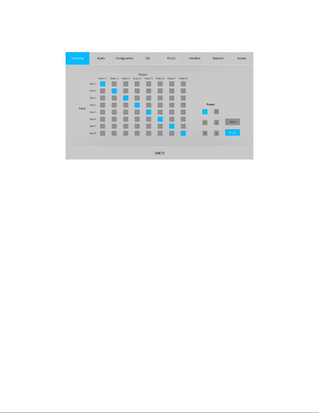
Switching Tab
• Use the 8x8 button grid on the left side of the screen to set which inputs are
directed to each of the eight outputs. For example, if you want to send Input 1 to
Outputs 1-4, click the Input 1 button in the Output 1, Output 2, Output 3, and Output
4 columns.
• Use the six numbered buttons in conjunction with the Save and Recall buttons to
save and load layout presets. Note that the matrix supports 9 presets, with presets
1-4 corresponding to the four PRESET RECALL buttons on the matrix front panel. The
three remaining presets can be managed using RS-232 control.
o To save a given layout, first click one of the numbered buttons, then click the
Save button.
o To load a previously saved layout, first click one of the numbered buttons, then
click the Recall button.
Page 22

22
Audio Tab
• Use the pull-down list boxes to select a source for the selected digital optical
S/PDIF audio output. For each S/PDIF output you can select the audio from any of
the eight inputs, the audio from any of the eight outputs, or the ARC audio from the
six HDBaseT™ outputs.
Page 23

23
Configuration Tab
PoC
• Click the On or Off radio buttons to enable or disable the Power over Cable (PoC)
feature for each of the six HDBT outputs, then click the Confirm button to save the
changes.
• Click the Cancel button at any time to cancel any unsaved changes.
Page 24

24
EDID Copy
• Click one of the HDMI tabs above the radio buttons to select an input, then click
one of the six HDBT Out or two HDMI Out radio buttons, and finally click the
Confirm button to send the EDID® settings from the selected output to the selected
input.
• Click the Cancel button at any time to clear any unsaved changes.
Page 25

25
EDID Setting
• Click one of the HDMI tabs above the radio buttons to select an input, then click
one of the radio buttons other than the User-defined entry. and finally click the
Confirm button to send the selected fixed EDID® setting to the selected input.
• Click one of the HDMI tabs above the radio buttons to select an input, then click
the User-defined radio button. Click inside the box with the .bin label, locate and
select the file with your custom EDID settings, then click the Apply button to load
your custom EDID settings, and finally click the Confirm button to send your custom
EDID to the selected input.
Note: You can create the .bin file with the custom EDID settings using HDMI® EDID
programming software.
• Click the Cancel button at any time to cancel any unsaved changes.
Page 26

26
CEC Tab
Input
• Click one of the radio buttons in the Input section to select an input device to
control, then click one of the buttons in the Function section to send the command
to the selected video input device. Note that your device must support the
Consumer Electronics Control (CEC) HDMI® feature to be controlled using the Web
GUI or IR remote control and only a single source device can be controlled at a time.
Page 27

27
Output
• Click one of the radio buttons in the Display section to select a display to control,
then click one of the buttons in Function section to send the command to the
selected display. Note that your display must support the Consumer Electronics
Control (CEC) HDMI® feature to be controlled using the Web GUI or IR remote
control and only a single display can be controlled at a time.
Page 28

28
RS232 Tab
Local
• Click the Local radio button to send RS-232 commands to the matrix.
• Click the HEX radio button to specify that your RS-232 command will be in hex
format or click the ASCII radio button to specify that your RS-232 command will be
in ASCII format.
• Use the pull-down list box next to the Baud Rate label to select the speed at which
your RS-232 command is sent. You can select 2400, 4800, 9600, 19200, 38400,
57600, and 115200 baud.
• Use the pull-down list box next to the Command Ending label to select the
termination for your RS-232 command. You can select NULL, CR, LF, or CR+LF.
• Type your RS-232 command into the Command field, then click the Send button to
send the command using the selected format, baud rate, and termination settings.
See the
RS-232 COMMANDS
section for a list of valid RS-232 commands.
• Click the Cancel button at any time to clear any unsent command.
Page 29

29
HDBT
• Click the HDBT radio button to send RS-232 commands to one of the HDBaseT™
receivers to control a connected third-party device.
• Click one of the radio buttons in the Port section to select which HDBaseT receiver
will receive the RS-232 command.
• Click the HEX radio button to specify that your RS-232 command will be in hex
format or click the ASCII radio button to specify that your RS-232 command will be
in ASCII format.
• Use the pull-down list box next to the Baud Rate label to select the speed at which
your RS-232 command is sent. You can select 2400, 4800, 9600, 19200, 38400,
57600, and 115200 baud.
• Use the pull-down list box next to the Command Ending label to select the
termination for your RS-232 command. You can select NULL, CR, LF, or CR+LF.
• Type your RS-232 command into the Command field, then click the Send button to
send the command using the selected format, baud rate, and termination settings.
See the
RS-232 COMMANDS
section for a list of valid RS-232 commands.
• Click the Cancel button at any time to clear any unsent command.
Page 30

30
Interface Tab
• Type a new title into the field next to the Title Bar Label, then click the Confirm
button to save the change. The title is displayed at the bottom of each page in the
Web GUI.
• You can type new labels into the Button Labels fields. These button labels are
displayed on the Switching Tab. Click the Confirm button to save the changes.
• Click the Cancel button at any time to cancel any unsaved changes.
Page 31

31
Network Tab
• The MAC Address entry shows the MAC address of the matrix.
• Click the slider under the MAC Address entry to change between using the Dynamic
Host Configuration Profile (DHCP) to automatically determine your IP address or the
Static IP address shown on this page.
• Enter new IP Address, Subnet Mask, and Gateway addresses, then click Confirm to
save the changes. Once changed, the Web GUI is accessed using the new address.
• Click the Cancel button at any time to cancel any unsaved changes.
Page 32

32
Access Tab
• Type a new password into the field next to the Password label, then click the
Confirm button to change the login password. Note that passwords are case
sensitive. The default password is admin.
• Click the slider under the Front Panel Lock label to lock or unlock the front panel
buttons. When locked, the front panel buttons cannot be used to control the matrix.
Page 33

33
WEB GUI UPGRADE
In the event that the Web GUI software in the matrix changes, a Web GUI upgrade file will
be made available for download on the product page on the Monoprice.com website.
Perform the following steps to download and apply the Web GUI upgrade.
1. Open a web browser and type monoprice.com on the address bar, then hit enter.
2. On the Monoprice website, type 39670 into the search bar and hit enter.
3. Go to the bottom of the page and look for the Support Files section. Locate and
download the new Web GUI update zip file. Note the location to which you
downloaded the file.
4. Extract the update file from the downloaded zip file.
5. In your web browser, type http://192.168.0.178: 100 into the address bar and hit
enter.
6. Enter the User Name and Password on the login screen, then click the Login button.
The default User Name is admin and the default Password is admin. The following
screen will be displayed.
7. Click the Administration entry on the left, then click the Upload Firmware entry.
8. Click the Choose File button, then locate and select the update file on your
computer.
9. Click the Apply button, then follow the on-screen instructions.
Page 34

34
RS-232 CONNECTION
This section details the various ways you can connect your computer and any third-party
devices for matrix and third-party device control.
Controlling the Matrix with a PC Connected to the Matrix
• Plug one end of the included RS-232 cable into the RS232 connector on the matrix
rear panel, then plug the other end into an available COM port on your PC.
Page 35

35
Controlling the Matrix with a PC Connected to a Receiver
1. Plug one end of the included RS-232 cable into the RS232 connector on one of the
receivers, then plug the other end into an available COM port on your PC.
2. Using RS-232 control software, send the RS232RCMxxON. command to enable
remote RS-232 control, where xx=00 for all HDBaseT™ receivers or 01-06 for an
individual receiver. Refer to the
RS-232 COMMANDS
section for command details.
Page 36

36
Controlling a Remote Third-Party Device with a PC Connected to the Matrix
1. Plug one end of the included RS-232 cable into the RS232 connector on the matrix
rear panel, then plug the other end into an available COM port on your PC.
2. Plug one end of a second RS-232 cable (not included) in the RS232 connector on one
of the receivers, then plug the other end into the RS-232 control connector on your
third-party device.
Page 37

37
Control a Local Third-Party Device with a PC Connected to a Receiver
1. Plug one end of the included RS-232 cable into the RS232 connector on one of the
receivers, then plug the other end into an available COM port on your PC.
2. Plug one end of a second RS-232 cable (not included) in the RS232 connector on the
matrix, then plug the other end into the RS-232 control connector on your third-
party device.
3. Using RS-232 control software, send the RS232RCMxxON. command to enable
remote RS-232 control, where xx=00 for all HDBaseT™ receivers or 01-06 for an
individual receiver. Refer to the
RS-232 COMMANDS
section for command details.
Page 38

38
RS-232 CONTROL
The matrix can be controlled using RS-232 commands issued from RS-232 control software.
Before you can issue RS-232 commands, you must plug one end of the included RS-232
Cable into the RS232 terminal block on the matrix rear panel, then plug the other end into
an available serial port on your computer.
Next, you need to download and install RS-232 control
software. A common freeware RS-232 control software is
CommWatch.exe, which this section will use as an example,
but other software can be used instead.
The default communications parameters are:
Baud Rate: 9600
Data Bits: 8
Stop Bits: 1
Parity: None
Page 39

39
RS-232 COMMANDS
This section details all available RS-232 commands. These commands can be entered using
RS-232 control software or on the RS232 tab in the Web GUI.
Notes:
• In the following commands, the [ and ] characters are used to make it easier to read
the command. Do not enter these characters.
• The period at the end is part of the command and must be included for the
command to work.
• The commands are case sensitive, so enter them exactly as shown in the tables
below.
System Settings
Command
Description
Feedback Example
PowerON.
Turns the system on.
Power ON!
HDBT 01 Power ON!
HDBT 02 Power ON!
HDBT 03 Power ON!
HDBT 04 Power ON!
HDBT 05 Power ON!
HDBT 06 Power ON!
Front Panel UnLock!
PowerOFF.
Turns the system off.
Power OFF!
/*Name.
Reports the system name.
39670
/*Type.
Reports the system model.
HDBaseT Matrix
/^Version.
Reports the firmware and video
driver versions.
V1.0.0
CPLD:V1.0.0
VideoDriverVersion:V1.0.0
Page 40

40
Command
Description
Feedback Example
RST.
Resets the matrix to the factory
default values.
Factory Default!
System Initialization......
HDBaseT Matrix
39670
V1.0.0
Power ON!
. . . . . .
Lock.
Lock the front panel buttons.
Front Panel Locked!
Unlock.
Unlocks the front panel buttons.
Front Panel UnLock!
GetGuiIP.
Reports the GUI IP address.
GUI_IP:192.168.0.178!
SetGuiIP:xxx.xxx.xxx.xxx
Sets the GUI IP to xxx.xxx.xxx.xxx.
SetGuiIP:192.168.0.178!
Baudrate115200.
Sets the baud rate of the matrix
to 115200 baud.
Set Local RS232 Baudrate Is
115200!
Baudrate57600.
Sets the baud rate of the matrix
to 57600 baud.
Set Local RS232 Baudrate Is
57600!
Baudrate38400.
Sets the baud rate of the matrix
to 38400 baud.
Set Local RS232 Baudrate Is
38400!
Baudrate19200.
Sets the baud rate of the matrix
to 19200 baud.
Set Local RS232 Baudrate Is
19200!
Baudrate9600.
Sets the baud rate of the matrix
to 9600 baud.
Set Local RS232 Baudrate Is
9600!
IRFVON.
Enable IR switching to follow
video switching.
IR Follow Video ON!
IRFVOFF.
Disable IR switching to follow
video switching.
IR Follow Video OFF!
Page 41

41
Command
Description
Feedback Example
PHDBT[xx]:ON
Turns on the Power over Cable
(PoC) feature for HDBT output
[xx]. [xx]=00~06, where 00
represents all HDBT outputs.
Example: PHDBT00:ON
Feedback:
HDBT 01 Power ON!
HDBT 02 Power ON!
HDBT 03 Power ON!
HDBT 04 Power ON!
HDBT 05 Power ON!
HDBT 06 Power ON!
PHDBT[xx]:OFF.
Turns off the Power over Cable
(PoC) feature for HDBT output
[xx]. [xx]=00~06, where 00
represents all HDBT outputs.
Example: PHDBT00:OFF.
Feedback:
HDBT 01 Power OFF!
HDBT 02 Power OFF!
HDBT 03 Power OFF!
HDBT 04 Power OFF!
HDBT 05 Power OFF!
HDBT 06 Power OFF!
STA_PHDBT.
Reports the Power over Cable
(PoC) status of the HDBT
outputs.
HDBT 01 Power ON!
HDBT 02 Power ON!
HDBT 03 Power OFF!
HDBT 04 Power ON!
HDBT 05 Power ON!
HDBT 06 Power OFF!
Page 42

42
Command
Description
Feedback Example
RS232RCM[xx]ON.
Enables RS-232 remote control
mode for HDBT output [xx] to
allow for control of the matrix
from the HDBaseT™ receiver [xx].
[xx]=00~06, where 00 represents
all HDBT outputs.
Example: RS232RCM00ON.
Feedback:
RS232 Remote 01 Control
MCU ON!
RS232 Remote 02 Control
MCU ON!
RS232 Remote 03 Control
MCU ON!
RS232 Remote 04 Control
MCU ON!
RS232 Remote 05 Control
MCU ON!
RS232 Remote 06 Control
MCU ON!
RS232RCM[xx]OFF.
Disables RS-232 remote control
mode for HDBT output [xx] to
allow for control of the matrix
from the HDBaseT™ receiver [xx].
[xx]=00~06, where 00 represents
all HDBT outputs.
Example: RS232RCM00OFF.
Feedback:
RS232 Remote 01 Control
MCU OFF!
RS232 Remote 02 Control
MCU OFF!
RS232 Remote 03 Control
MCU OFF!
RS232 Remote 04 Control
MCU OFF!
RS232 Remote 05 Control
MCU OFF!
RS232 Remote 06 Control
MCU OFF!
Page 43

43
Command
Description
Feedback Example
STA_RS232RCM.
Reports the RS-232 remote
control mode status.
RS232 Remote 01 Control
MCU OFF!
RS232 Remote 02 Control
MCU ON!
RS232 Remote 03 Control
MCU ON!
RS232 Remote 04 Control
MCU ON!
RS232 Remote 05 Control
MCU OFF!
RS232 Remote 06 Control
MCU OFF!
IRRCM[xx]ON.
Enables IR remote control mode
for HDBT output [xx] to control
the matrix using the included IR
remote control from the
HDBaseT™ receiver locations.
[xx]=00~06, where 00 represents
all HDBT outputs.
Example: IRRCM00ON.
Feedback:
IR Remote 01 Control MCU
ON!
IR Remote 02 Control MCU
ON!
IR Remote 03 Control MCU
ON!
IR Remote 04 Control MCU
ON!
IR Remote 05 Control MCU
ON!
IR Remote 06 Control MCU
ON!
Page 44

44
Command
Description
Feedback Example
IRRCM[xx]OFF.
Disables IR remote control mode
for HDBT output [xx] to control
the matrix using the included IR
remote control from the
HDBaseT™ receiver locations.
[xx]=00~06, where 00 represents
all HDBT outputs.
Example: IRRCM00OFF.
Feedback:
IR Remote 01 Control MCU
OFF!
IR Remote 02 Control MCU
OFF!
IR Remote 03 Control MCU
OFF!
IR Remote 04 Control MCU
OFF!
IR Remote 05 Control MCU
OFF!
IR Remote 06 Control MCU
OFF!
STA_IRRCM.
Reports the IR remote control
mode status.
IR Remote 01 Control MCU
OFF!
IR Remote 02 Control MCU
ON!
IR Remote 03 Control MCU
ON!
IR Remote 04 Control MCU
ON!
IR Remote 05 Control MCU
OFF!
IR Remote 06 Control MCU
ON!
Page 45

45
Command
Description
Feedback Example
@OUT[xx].
Turns on output [xx]. [xx]=00~08,
where 00 represents all outputs.
Example: @OUT00.
Turn ON Output 01!
Turn ON Output 02!
Turn ON Output 03!
Turn ON Output 04!
Turn ON Output 05!
Turn ON Output 06!
Turn ON Output 07!
Turn ON Output 08!
$OUT[xx].
Turns off output [xx].
[xx]=00~08, where 00 represents
all outputs.
Example: $OUT00.
Feedback:
Turn OFF Output 01!
Turn OFF Output 02!
Turn OFF Output 03!
Turn OFF Output 04!
Turn OFF Output 05!
Turn OFF Output 06!
Turn OFF Output 07!
Turn OFF Output 08!
STA.
Reports the system status.
GUI OR RS232 Query
Status:
HDBaseT Matrix
39670
V1.0.0
Power ON!
. . . . . .
Page 46

46
Command
Description
Feedback Example
STA_POUT.
Reports the status of all outputs.
Turn ON Output 01!
Turn ON Output 02!
Turn OFF Output 03!
Turn OFF Output 04!
Turn ON Output 05!
Turn ON Output 06!
Turn OFF Output 07!
Turn ON Output 08!
STA_IN.
Reports the connection status of
all HDMI® inputs.
IN 1 2 3 4 5 6 7 8
LINK Y N N Y Y Y Y Y
STA_OUT.
Reports the connection status of
all HDMI and HDBT outputs.
OUT 1 2 3 4 5 6 7 8
LINK Y N N Y Y Y Y Y
Signal Switching
Command
Description
Feedback Example
OUT[xx]:[yy].
Switch video input [yy] to video
output [xx]. [xx]=00~08, where
00 represents all outputs.
[yy]=01~08.
Example: OUT01:03.
Feedback:
Output 01 Switch To In 03!
Local 03 IR Out Switch To
Remote 01 IR IN!
STA_VIDEO.
Reports the selected input for
each output.
Output 01 Switch To In 03!
Output 02 Switch To In 07!
Output 03 Switch To In 03!
Output 04 Switch To In 01!
Output 05 Switch To In 02!
Output 06 Switch To In 08!
Output 07 Switch To In 04!
Output 08 Switch To In 04!
Page 47

47
Command
Description
Feedback Example
IR[xx]:[yy].
Switches remote IR IN [yy] to
local IR OUT [xx]. [xx]=01~08.
[yy]=00~06, where 00 represents
all remote IR IN ports.
Example: IR01:03.
Feedback:
Local 01 IR Out Switch To
Remote 03 IR IN!
STA_IR.
Reports the IR switching status.
IR Follow Video OFF!
Local 01 IR Out Switch To
Remote 01 IR IN!
Local 01 IR Out Switch To
Remote 02 IR IN!
Local 01 IR Out Switch To
Remote 03 IR IN!
Local 01 IR Out Switch To
Remote 04 IR IN!
Local 01 IR Out Switch To
Remote 05 IR IN!
Local 01 IR Out Switch To
Remote 06 IR IN!
PresetSave[xx].
Saves the current switching
layout to preset [xx]. [xx]=01~09.
Example: PresetSave09.
Feedback:
Preset 09 Sta:
Out 01 In 01!
Out 02 In 04!
Out 03 In 05!
Out 04 In 04!
Out 05 In 06!
Out 06 In 03!
Out 07 In 06!
Out 08 In 08!
Page 48

48
Command
Description
Feedback Example
PresetRecall[xx].
Loads the switching layout for
preset [xx]. [xx]=01~09.
Example: PresetRecall09.
Feedback:
Output 01 Switch To In 01!
Output 02 Switch To In 04!
Output 03 Switch To In 05!
Output 04 Switch To In 04!
SPDIF Out 03 Switch To
Video Out 04!
Output 05 Switch To In 06!
Output 06 Switch To In 03!
Output 07 Switch To In 06!
Output 08 Switch To In 08!
PresetSta[xx].
Reports the switching layout for
preset [xx]. [xx]=01~09.
Example: PresetSta06.
Feedback:
Preset 06 Sta:
Out 01 In 01!
Out 02 In 01!
Out 03 In 03!
Out 04 In 04!
Out 05 In 03!
Out 06 In 03!
Out 07 In 06!
Out 08 In 05!
Page 49

49
Audio Settings
Command
Description
Feedback Example
SPDIF[xx]:[yy].
Selects audio source [yy] for
SPDIF audio output [xx].
[xx]=00~08, where 00 represents
all SPDIF audio outputs.
[yy]=01~22.
[yy]=01~08 represents Input 1~8.
[yy]=09~16 represents Output
1~8.
[yy]=17~22 represents ARC on
Output 1~6.
Example: SPDIF01:04.
Feedback:
SPDIF Out 01 Switch To
Video In 04!
STA_SPDIF.
Reports the S/PDIF audio status.
SPDIF Out 01 Switch To
Video In 01!
SPDIF Out 02 Switch to
ARC 03!
SPDIF Out 03 Switch to
Video Out 04!
SPD
Page 50

50
EDID Management
Command
Description
Feedback Example
EDIDMInit.
Resets the EDID® of all inputs to
the factory default setting.
All Input EDID Set Default!
EDIDUpgrade[xx].
Upgrades the EDID data of input
port [xx]. [xx]=00~08 or U, where
00 represents all inputs and U
instructs to upload a user-
defined EDID.
When the command is applied
the system prompts to upload
the EDID file (.bin). The operation
will be cancelled after 10
seconds. Please disconnect the
HDBT connection before sending
the command to ensure the data
can be successfully received.
256
9600bps
Input XX/User Define EDID
Upgrade OK BY RS232 Or
GUI!
Page 51

51
Command
Description
Feedback Example
EDID/[xx]/[yy].
Assign embedded EDID [yy] to
input [xx]. [xx]=00~08, where 00
represents all inputs. [yy]=01~09,
where:
01=1920x1080@60Hz, 8-bit
Stereo Audio
02=1920x1080@60Hz 8-bit High
Definition Audio
03=3840x2160@30Hz 8-bit
Stereo Audio
04=3840x2160@30Hz Deep Color
High Definition Audio
05=3840x2160@60Hz 4:2:0 Deep
Color Stereo Audio
06=3840x2160@60Hz Deep Color
Stereo Audio
07=3840x2160@60Hz Deep Color
High Definition Audio
08=3840x2160@60Hz Deep Color
HDR LPCM 6-channel Audio
09=User-defined EDID®
Example: EDID/03/01.
Feedback:
Input 03 EDID Upgrade OK
By 01 Internal EDID!
EDIDGOUT[xx].
Reports the EDID data from
output [xx]. [xx]=01~08.
Example: EDIDGOUT04.
Feedback:
. . . . . .
Page 52

52
Command
Description
Feedback Example
EDIDM[xx]B[yy].
Copies the EDID data of output
[xx] to input [yy]. [xx]=01~08.
[yy]=00~08, where 00 represents
all inputs.
Example: EDIDM04B01.
Feedback:
Input 01 EDID Upgrade OF
By 04 EXT EDID!
EDIDSTA[xx].
Reports the EDID status of input
[xx]. [xx]=00~08, where 00
represents all inputs.
Example: EDIDSTA00.
Feedback:
Input 01 EDID From 01
Internal EDID!
Input 02 EDID From 02
Internal EDID!
. . . . . .
Input 07 EDID From 06
Internal EDID!
Input 08 EDID From User
Define EDID!
Page 53

53
HDCP Management
Command
Description
Feedback Example
HDCP[xx]MAT.
The HDCP™ content of output
[xx] follows the HDCP version of
the connected display.
[xx]=00~08 where 00 represents
all outputs.
Example: HDCP00MAT.
Feedback:
OUT 01 HDCP MAT Display!
OUT 02 HDCP MAT Display!
OUT 03 HDCP MAT Display!
OUT 04 HDCP MAT Display!
OUT 05 HDCP MAT Display!
OUT 06 HDCP MAT Display!
OUT 07 HDCP MAT Display!
OUT 08 HDCP MAT Display!
HDCP[xx]PAS.
Sets the HDCP mode of output
[xx] to Passive. The HDCP
content of output [xx]
automatically follows the HDCP
version of the source device.
[xx]=00~08, where 00 represents
all outputs.
Example: HDCP00PAS.
Feedback:
OUT 01 HDCP PASSIVE!
OUT 02 HDCP PASSIVE!
OUT 03 HDCP PASSIVE!
OUT 04 HDCP PASSIVE!
OUT 05 HDCP PASSIVE!
OUT 06 HDCP PASSIVE!
OUT 07 HDCP PASSIVE!
OUT 08 HDCP PASSIVE!
Page 54

54
Command
Description
Feedback Example
HDCP[xx]BYP.
Sets the HDCP™ mode of output
[xx] to Active. If the input video
has HDCP content, the HDCP
version of the HDMI® output is
HDCP 1.4 for broader video
compatibility. If the input video
has no HDCP content, the HDMI
output has no HDCP, either.
[xx]=00~08 where 00 represents
all outputs.
Example: HDCP00BYP.
Feedback:
OUT 01 HDCP BYPASS!
OUT 02 HDCP BYPASS!
OUT 03 HDCP BYPASS!
OUT 04 HDCP BYPASS!
OUT 05 HDCP BYPASS!
OUT 06 HDCP BYPASS!
OUT 07 HDCP BYPASS!
OUT 08 HDCP BYPASS!
STA_HDCP.
Reports the HDCP mode of all
outputs.
OUT 01 HDCP PASSIVE!
OUT 02 HDCP PASSIVE!
OUT 03 HDCP MAT
DISPLAY!
OUT 04 HDCP BYPASS!
OUT 05 HDCP BYPASS!
OUT 06 HDCP BYPASS!
OUT 07 HDCP BYPASS!
OUT 08 HDCP BYPASS!
Page 55

55
Third-Party Device Control
Command
Description
Feedback Example
/+[x]/[yy]:xxx.
Sends the ASCII command xxx at
baud rate [x] to control the
remote third-party device
connected to the HDBaseT™
receiver connected to HDBT
output [yy].
xxx=ASCII string.
[x]=1~7 represents the baud rate
of the third-party device.
[x]=1, the baud rate is 2400
[x]=2, the baud rate is 4800
[x]=3, the baud rate is 9600
[x]=4, the baud rate is 19200
[x]=5, the baud rate is 38400
[x]=6, the baud rate is 57600
[x]=7, the baud rate is 115200
[yy]=00~06 where 00 represents
all HDBT outputs.
Example: +3/01:123456.
Sends the ASCII command
123456 at 9600 baud to the
third-party device
connected to the HDBaseT
receiver connected to
HDBT output port 1.
Page 56

56
Command
Description
Feedback Example
CMDON/+[x]/[yy]:xxx.
When the matrix is powered on,
automatically sends the ASCII
command xxx at baud rate [x] to
the third-party device connected
to the HDBaseT™ receiver
connected to HDBT output [yy].
xxx=ASCII string.
[x]=1~7 represents the baud rate
of the third-party device.
[x]=1, the baud rate is 2400
[x]=2, the baud rate is 4800
[x]=3, the baud rate is 9600
[x]=4, the baud rate is 19200
[x]=5, the baud rate is 38400
[x]=6, the baud rate is 57600
[x]=7, the baud rate is 115200
[yy]=00~06 where 00 represents
all HDBT outputs.
Example:
CMDON/+3/01:123456.
Automatically sends the
ASCII command 123456 at
9600 baud to the HDBaseT
receiver connected to
HDBT output 1 when the
matrix is powered on.
Page 57

57
Command
Description
Feedback Example
CMDOFF/+[x]/[yy]:xxx.
When the matrix is powered off,
automatically sends the ASCII
command xxx at baud rate [x] to
the third-party device connected
to the HDBaseT™ receiver
connected to HDBT output [yy].
xxx=ASCII string.
[x]=1~7 represents the baud rate
of the third-party device.
[x]=1, the baud rate is 2400
[x]=2, the baud rate is 4800
[x]=3, the baud rate is 9600
[x]=4, the baud rate is 19200
[x]=5, the baud rate is 38400
[x]=6, the baud rate is 57600
[x]=7, the baud rate is 115200
[yy]=00~06 where 00 represents
all HDBT outputs.
Example:
CMDOFF/+3/01:123456.
Automatically sends the
ASCII command 123456 at
9600 baud to the HDBaseT
receiver connected to
HDBT output 1 when the
matrix is powered off.
Page 58

58
CEC Control
The command structure for Consumer Electronics Control (CEC) commands is:
CEC[I/O][AA][BB][CC][DD].
• [I] represents a command for an input device and [O] represents a command for the
connected display.
• [AA] represents the port number. The HDMI® input ports are 01~08. The HDBaseT™
output ports are 01~06 and the local HDMI output ports are 07~08.
• [BB] represents the device type (e.g., TV: 40/20/80, Blu-ray Disc™ player: 04/08).
• [CC] represents the function type (e.g., Remote control: 44).
• [DD] represents the specific command from the following table.
Command
Description
Feedback Example
CECI[AA][BB][CC]00.
Confirm operation (Enter).
Example: CECI02044400.
Feedback:
CEC Input 02 Send Success!
CECI[AA][BB][CC]01.
UP direction.
Example: CECI01044401.
Feedback:
CEC Input 01 Send Success!
CECI[AA][BB][CC]02.
DOWN direction.
Example: CECI01044402.
Feedback:
CEC Input 01 Send Success!
CECI[AA][BB][CC]03.
LEFT direction.
Example: CECI03044403.
Feedback:
CEC Input 03 Send Success!
Page 59

59
Command
Description
Feedback Example
CECI[AA][BB][CC]04.
RIGHT direction.
Example: CECI03044404.
Feedback:
CEC Input 03 Send Success!
CECI[AA][BB][CC]09.
Back to submenu.
Example: CECI03044409.
Feedback:
CEC Input 03 Send Success!
CECI[AA][BB][CC]0A.
Enter main menu.
Example: CECI0304440A.
Feedback:
CEC Input 03 Send Success!
CECI[AA][BB][CC]0D.
Exit menu.
Example: CECI0204440D.
Feedback:
CEC Input 02 Send Success!
CECI[AA][BB][CC]6D.
Power on.
Example: CECI0204446D.
Feedback:
CEC Input 02 Send Success
CECI[AA][BB][CC]6C.
Power off.
Example: CECI0204446C.
Feedback:
CEC Input 02 Send Success!
CECO[AA][BB][CC]41.
Volume up.
Example: CECO05404441.
Feedback:
CEC Output 05 Send
Success!
Page 60

60
Command
Description
Feedback Example
CECO[AA][BB][CC]42.
Volume down.
Example: CECO05404441.
Feedback:
CEC Output 05 Send
Success!
CECO[AA][BB][CC]43.
Mute on/off.
Example: CECO05404441.
Feedback:
CEC Output 05 Send
Success!
CECO[AA][BB][CC]04.
Power on.
Example: CECO038004.
Feedback:
CEC Output 03 Send
Success!
CECO[AA][BB][CC]36.
Power off.
Example: CECO038036.
Feedback:
CEC Output 05 Send
Success!
Page 61

61
FIRMWARE UPGRADE
In the event that the firmware in the matrix changes, an upgrade file will be made available
for download on the product page on the Monoprice.com website. Perform the following
steps to download and apply the firmware upgrade.
1. Open a web browser and type monoprice.com on the address bar, then hit enter.
2. On the Monoprice website, type 39670 into the search bar and hit enter.
3. Go to the bottom of the page and look for the Support Files section. Locate and
download the new Firmware update zip file. Note the location to which you
downloaded the file.
4. Extract the update file from the downloaded zip file and rename it 08010000.APP.
5. Plug a USB flash drive into an available USB port on your PC.
6. Change the volume name of the USB flash drive to BOOTDISK.
7. Copy the 08010000.APP file onto the USB flash drive. Check the contents of the USB
flash drive to ensure that a file named READY.TXT is present.
8. Remove the USB flash drive from your PC.
9. Ensure that the matrix is powered off, then plug the USB flash drive into the FW
port on the rear panel.
10. Turn the matrix on to automatically update the firmware.
11. When the process is complete, remove the USB flash drive from the matrix and plug
it into an available USB port on your PC.
12. Check the contents of the USB flash drive. If the READY.TXT file is no longer present
and a SUCCESS.TXT file is present, the firmware has been successfully updated. If
not, delete the contents of the USB flash drive, then repeat steps 6-12.
13. Once the firmware has been successfully updated, restore the matrix to its factory
default settings by issuing the RST. RS-232 command.
Page 62

62
TROUBLESHOOTING
Q1: The video signal is losing color or there is no video output.
A1: Ensure that the cables are properly plugged in. Check that the cable is good by
replacing it with a known good one.
Q2: There is no output image when switching.
A2: Ensure that the cables are properly plugged in. Check that output HDCP™ compliance
is enabled. Check that the display supports the selected video resolution. Use an
oscilloscope or multimeter to verify that there is a signal at the input and output ends.
Q3: The front panel buttons do not work.
A3: Ensure that the front panel buttons are not locked.
Q4: The IR remote control does not work.
A4: Ensure that you are using the remote within the IR range and at the proper angle.
Replace the remote control's battery. Ensure that the IR receiver is properly plugged in.
Try replacing the IR receiver.
Q5: The POWER LED on the front panel remains off, even after switching power on.
A5: Ensure that the power cord is properly plugged in. Verify that the power outlet has
power by plugging in another device, such as a lamp.
Q6: EDID® management does not work properly.
A6: Try replacing the HDMI® cable with a known good one.
Page 63

63
Q7: The screen on the display is blank when switching.
A7: Try switching again. Manually adjust the EDID® data to set a usable video resolution for
the video source.
Q8: The matrix cannot be controlled using RS-232 commands.
A8: Check the RS-232 cable connection at each end. Ensure that the RS-232
communication parameters are set as baud rate=9600, data bits=8, stop bits=1,
parity=none. Try using a different COM port.
TECHNICAL SUPPORT
Monoprice is pleased to provide free, live, online technical support to assist you with any
questions you may have about installation, setup, troubleshooting, or product
recommendations. If you ever need assistance with your new product, please come online
to talk to one of our friendly and knowledgeable Tech Support Associates. Technical
support is available through the online chat button on our website www.monoprice.com
or through email by sending a message to tech@monoprice.com. Check the website for
support times and links.
SPECIFICATIONS
Matrix
Model
39670
Video Inputs
8x HDMI®
Video Outputs
6x HDBaseT™, 2x HDMI
Maximum HDMI Output Resolution
4K@60Hz with YCbCr 4:4:4
Maximum HDBaseT Output Resolution
4K@60Hz with YCbCr 4:2:0
Bandwidth
18 Gbps
Page 64

64
HDMI Version
2.0
HDCP™ Version
2.2
Audio Outputs
4x digital optical S/PDIF
Audio Frequency Response
20Hz ~ 20kHz, ±1dB
Maximum Output Level
±0.05dBFS
THD+N
< 0.05%, 20Hz ~ 20kHz bandwidth, 1kHz
sine at 0dBFS level (or max level)
Signal-to-Noise Ratio
> 90dB, 20Hz ~ 20kHz bandwidth
Crosstalk Isolation
> -70dB, 10kHz sine at 0dBFS level (or max
level before clipping)
Noise Level
-90dB
Transmission Standard
HDBaseT™
Maximum Transmission Distance
1080p@60Hz: ≤ 229 feet (70 meters)
4K@60Hz: ≤ 131 feet (40 meters)
Input Power
100 ~ 240 VAC, 50/60 Hz
Maximum Power Consumption
92 watts
Operating Temperature
+23 ~ +131°F (-5 ~ +55°C)
Storage Temperature
-13 ~ +158°F (-25 ~ +70°C)
Operating Humidity
10 ~ 90% RH, noncondensing
Dimensions
17.2" x 1.7" x 15.2" (436 x 44 x 385 mm)
Weight
10.7 lbs. (4.87 kg)
Page 65

65
Receivers
Video Input
1x HDBaseT™
Video Output
1x HDMI®
Maximum Input Resolution
4K@60Hz with YCbCr 4:2:0
Maximum Output Resolution
4K@60Hz with YCbCr 4:4:4 8-bit HDR10
Transmission Standard
HDBaseT
Maximum Transmission Distance
1080p@60Hz: ≤ 229 feet (70 meters)
4K@60Hz: ≤ 131 feet (40 meters)
HDMI® Version
2.0
HDCP™ Version
2.2, 1.4 compliant
Bandwidth
18 Gbps
Maximum Output Level
2.0Vrms ±0.5dB, 2V = 16dB headroom
above -10dBV (316mV) nominal consumer
line level signal
THD+N
< 0.05% (-80dB), 20Hz ~ 20kHz bandwidth,
1kHz sine at 0dBFS level (or max level)
Signal-to-Noise Ratio
> 85dB, 20Hz ~ 20kHz bandwidth
Crosstalk Isolation
> -70dB, 10kHz sine at 0dBFS level (or max
level before clipping)
L/R Channel Separation
< 0.03dB, 1kHz sine at 0dBFS level (or max
level before clipping)
Frequency Response Deviation
< ±0.5dB 20Hz ~ 20kHz
Output Load Capability
1kΩ and higher (supports 10x paralleled
10kΩ loads)
Stereo Channel Separation
> 70dB @ 1kHz
Page 66

66
HDMI® 2.0 Cable Length
4K@60Hz YCbCr 4:4:4 ≤ 5m
4K@60Hz YCbCr 4:2:0 ≤ 15m
1080p ≤ 20m
Input Power
12 VDC 1.25A or Power over Cable (PoC)
AC Adapter Input Power
100 ~ 240 VAC, 50/60Hz
Maximum Power Consumption
12 watts
Operating Temperature
+23 ~ +131°F (-5 ~ +55°C)
Storage Temperature
-13 ~ +158°F (-25 ~ +70°C)
Operating Humidity
10 ~ 90% RH, noncondensing
Dimensions
1.6" x 0.8" x 3.3" (40 x 20 x 84 mm)
Weight
10.2 oz. (290 g)
REGULATORY COMPLIANCE
Notice for FCC
This device complies with Part 15 of the FCC rules. Operation is subject to the following
two conditions: (1) this device may not cause harmful interference, and (2) this device must
accept any interference received, including interference that may cause undesired
operation.
Modifying the equipment without Monoprice's authorization may result in the equipment
no longer complying with FCC requirements for Class B digital devices. In that event, your
right to use the equipment may be limited by FCC regulations, and you may be required to
correct any interference to radio or television communications at your own expense.
This equipment has been tested and found to comply with the limits for a Class B digital
device, pursuant to Part 15 of the FCC Rules. These limits are designed to provide
Page 67

67
reasonable protection against harmful interference in a residential installation. This
equipment generates, uses and can radiate radio frequency energy and, if not installed and
used in accordance with the instructions, may cause harmful interference to radio
communications. However, there is no guarantee that interference will not occur in a
particular installation. If this equipment does cause harmful interference to radio or
television reception, which can be determined by turning the equipment off and on, the
user is encouraged to try to correct the interference by one or more of the following
measures:
• Reorient or relocate the receiving antenna.
• Increase the separation between the equipment and receiver.
• Connect the equipment into an outlet on a circuit different from that to which the
receiver is connected.
• Consult the dealer or an experienced radio/TV technician for help.
Notice for Industry Canada
This Class B digital apparatus complies with Canadian ICES-003.
Cet appareil numérique de la classe B est conforme à la norme NMB-003 du Canada.
Blackbird™ is a trademark of Monoprice Inc.
HDBaseT™ and the HDBaseT Alliance logo are trademarks of the HDBaseT Alliance.
HDMI®, the HDMI Logo, and High-Definition Multimedia Interface are trademarks or registered
trademarks of HDMI Licensing LLC in the United States and other countries.
EDID® is a registered trademark of the Video Electronics Standards Association.
HDCP™ is a trademark of Digital Content Protection LLC.
Blu-ray Disc™, Blu-ray™, and the logos are trademarks of the Blu-ray Disc Association.
 Loading...