

Page 1
Page 2

4 Cameras & 4 Channel DVR Video Security System Bundle
Chapter 1 Overview....................................................................................1
1.1 Introduction....................................................................................1
1.2 Packaging and Accessories..........................................................1
1.3 Main Features...............................................................................1
1.4 Technical Parameters....................................................................2
1.5 Product Appearance and Interface Definition...............................3
1.6 Remote Controller.........................................................................4
1.7 Mouse............................................................................................5
Chapter 2 Quick Installation.......................................................................6
2.1 HDD Installation............................................................................6
2.2 Boot...............................................................................................6
2.3 System Login.................................................................................6
2.4 Shortcut Menu...............................................................................7
Chapter 3 Advanced Settings.....................................................................9
3.1 Main Menu.....................................................................................9
3.2 Recording Mode..........................................................................10
3.3 Video Search................................................................................11
3.4 Backup........................................................................................12
3.5 Hard Disk Management..............................................................13
3.6 Basic Setup.................................................................................13
3.7 Advanced.....................................................................................17
3.8 Domain Name Application...........................................................23
3.9 Port Forwarding...........................................................................27
Chapter 4 DVR Network...........................................................................29
4.1 Functional Characteristics...........................................................29
4.2 Installation and Download of Controls........................................29
4.3 IE Login.......................................................................................29
4.4 Real-Time Preview......................................................................30
4.5 Recording Playback....................................................................31
4.6 Recording Mode..........................................................................31
4.7 Alarm Setup.................................................................................32
4.8 PTZ Control.................................................................................32
4.9 Network Setup.............................................................................32
4.10 System Setup............................................................................33
Page 3

4 Cameras & 4 Channel DVR Video Security System Bundle
4.11 Host Info....................................................................................33
Chapter 5 Client Software & Player.........................................................34
5.1 Client Software............................................................................34
5.2 Video Player................................................................................34
Appendix 1 Q&A................................................................................39
Appendix 2 Hard Disk Space Occupation Calculation......................41
Appendix 3 Topology.........................................................................41
Page 4

4 Cameras & 4 Channel DVR Video Security System Bundle
Notes
u The power for this DVR is provided by a DC12V/3A power adapter. Please check
the power outlet before installation and ensure that it can meet the requirements
of the adaptor;
u Do not place the DVR in a location where it is subject to rain or moisture;
u Do not install the DVR in a location where it is subject to violent vibration;
u Do not install the DVR in a location where it is subjected to direct sunlight. Keep
the DVR away from any heat source or high temperature environment;
u The back panel should be at least 6 inches (15 cm) away from the wall or other
objects to facilitate fan cooling operation;
u The DVR should be operated within the temperature, humidity, and voltage
requirements listed in the technical specifications;
u Keep the DVR away from corrosive chemicals that may produce volatile gases;
u The DVR should be operated in low-dust environments and the area around the
DVR should be kept clean and tidy;
u The DVR should be properly grounded;
For best results, install a SATA hard drive into the DVR to store large amount of
video content generated by the security system.
Page 5

4 Cameras & 4 Channel DVR Video Security System Bundle
Chapter 1 Overview
1.1 Introduction
This product is an easy to use, do it yourself, 4/8-channel security system bundle.
Included in the bundle is a DVR and four infrared (IR) capable day/night video cameras.
The kit comes with everything you need to install and operate the security system
(optional hard drive for DVR not included). The DVR uses the latest SOC technology
and employs the H.264 video compression standard, with support for CIF, Half-D1, and
D1 resolutions. With a real-time network capability you can remotely monitor your
security system using your smartphone.
1.2 Packaging and Accessories
Following parts are included in the package:
• 4x Color Infrared Day/Night Cameras with ¼" Sharp 420TVL CCD
• 1x 4-channel H.264 DVR (optional hard drive not included)
• 4x 60-ft (18m) video extension cables
• 1x DC 12V/3A power adapter
• 1x 1-to-4 DC splitter cable
• 4x Camera mounting bracket
• 1x USB mouse
• 1x IR remote control with batteries
• 1x SATA hard drive data cable (installed in DVR)
• 1x SATA hard drive power cable (installed in DVR)
• 1x Software installation CD-ROM
1.3 Main Features
• Standard H.264 video compression format
• 16-bit true-color semi-transparent graphical menu interface
• A variety of recording modes: manual, timing, motion, and alarm recording
• Optimized 4-ch simultaneous playback (single playback for 8-ch models)
• A variety of backup options (USB disk, mobile hard disk, network attached
storage, etc.)
• One USB 2.0 port for data backup, one USB 1.1 port for mouse (included)
• Multi-functional operation: simultaneous recording, playback, monitor, backup,
and network transmission
• Dual stream technology
• Network support for implementation of multi-screen real-time browsing, system
configuration, and video copy and playback
• Supports mobile phone monitoring
• Supports event classification and precision time search and playback
• Easy and fast restoration of factory default settings
• Flexible USB interface for mouse
Page 6

4 Cameras & 4 Channel DVR Video Security System Bundle
1.4 Technical Parameters
Features Description
Operating system Embedded LINUX OS
Video compression H.264
Video/Audio input 4/8 CH BNC
Video/ Audio output 1 CH BNC
Alarm intput/output 4/8 CH input 1 CH output
Display spilt 1/4/8-channel
VGA output Supports 800*600 1024*768 1280*1024@60Hz
Multiplex operation Live, recording, network, mobile phone
surveillance simultaneously
Recording mode Timer/manual/motion detection/alarm
Recording frame rate PAL:25fps NTSC:30fps adjustable
Recording quality High, normal ,low
Recording resolution CIF/Half-D1/D1
Recording playback 4/8 channel playback simultaneously
Recording backup Supports USB flash disk, mobile hard disk,
network backup, etc.
HDD Support 1 SATA HDD capacity to 2TB
Network transmission 4/8 channels real-time network transmission
with CIF resolution
Capture function Supported
Email alarm Send pictures to the designated Email box
PTZ control Supported
PTZ protocol PELCO-D,PELCO-P
PIP Supported
Zoom Supported
Network and protocol 1 RJ-45 10/100M via Ethernet, supports TCP/IP,
SMTP, DHCP, DNS, DDNS, NTP, etc.
IE browser Supported, max five users online
Client software Supported, max five users online
CMS Supported
Dual stream Supported(main and secondary interchange)
Multi-language Supported
Mobile phone surveillance Supported
Windows,Symbian,IPhone,Blackberry,Android
Mouse interface USB 1.1
Backup interface USB 2.0
Remote controller Supported
User authority Supports multi-level user authority distribution
Power DC12V/3A
Working temperature +14 ~ +122°F (-10 ~ +50°C)
Working humidity 10%-90%
Dimensions (WxDxH) 10.8" x 8.4" x 1.8" (274 x 214 x 45 mm)
Page 7
4 Cameras & 4 Channel DVR Video Security System Bundle
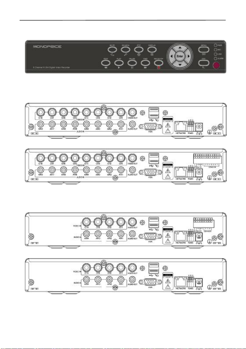
1.5 Product Appearance and Interface Definition
1.5.1 Front panel
1.5.2 Back panel
8CH
4CH
Page 8
4 Cameras & 4 Channel DVR Video Security System Bundle
No. Physical interface
1 1~4/8CH Video input Connect analog video signal input, standard BNC connector
2 Video output CVBS output and connection for the monitor
3 1~4/8CH Audio input Connect active audio signals, such as pickup
4 Audio output Connect the audio output
5 VGA Connect VGA monitor, such as computer monitor
6 NETWORK Connect the Ethernet cable
7 RS485 Connect the RS485 interface for equipment like PTZ
8 DC12V Power interface:DC 12V/3A
9 ALARM Connect alarm switch output
10 G
Interface description
Grounding: To eliminate electrostatic from chassis
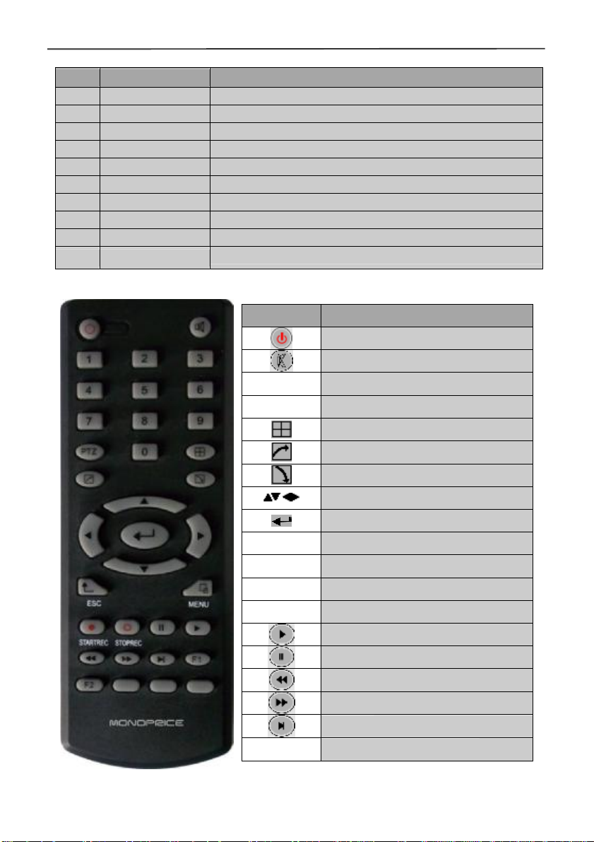
1.6 Remote Controller
Key Functional definition
Power ON/OFF
Mute
0~9 Channel selection; number keys
PTZ PTZ Control
Single and multi-split screen
Quit shortcut menu
Shortcut menu
Direction buttons
OK
ESC Exit / Return
MENU Enter the main menu
STARTREC Manual recording
STOPREC Stop recording
Video Search
Stop playing
Fast backward
Fast forward
Frame movement
F1, F2
Spare key
Page 9

4 Cameras & 4 Channel DVR Video Security System Bundle
1.7 Mouse
This device supports a USB 1.1 mouse for system menu operations. Any USB mouse
can be used, though one is included with the package.
Mouse
action
Right click Enters the system main menu, left click outside the menu to close it
Double
mouse left
click
Click the left
mouse
button
Function
The image in a channel can be enlarged by double click real-time
monitoring and playback screen, it can be recovered into monitoring
and multi-split image after double click again
Single left click the functional menu icon to enter menu setting page.
Access to volume adjustment, color adjustment and PTZ control
menu. The volume adjustment, color adjustment and PTZ control can
set only one channel, please select corresponding screen if
multi-screen mode is on prior to setting.
If you single click mouse button in volume adjustment and PTZ
control: PTZ control is available if clicking direction or "+ and -" icon;
There is a volume bar in volume control interface. Move mouse to a
position and click right button, the corresponding volume will be
shown in the right side of the volume bar, click "×" to exit;
Other operations, such as the color adjustment, can be controlled in
the same way as the volume adjustment above.
If there are many options in the option box, click the left button and a
drop-down menu will be shown.
Fast forward and fast backward function can be activated by left
clicking in the video playback interface.
Click the left button or right button to activate the soft keyboard in the
input box, clicking the right button can switch between English and
Chinese input states; number, symbol and English word capitalization
functions can be performed only by clicking.
The Chinese spell is also available via the soft keyboard input when
Chinese input, its input method is the same as remote control; left
button can be used for turning page.
Mouse
movement
Clicking the left button and move the mouse to adjust the parameters
in the volume and color adjustment interfaces. There is a
corresponding parameter display on the right side when moving the
mouse.
Click the left button and move the mouse to set the dynamic detection
zone in for the motion detection zone.
Page 10

4 Cameras & 4 Channel DVR Video Security System Bundle
Chapter 2 Quick Installation
2.1 HDD Installation
Hard disk installation should be performed by a technician to avoid damage to the
equipment and hard disk. The DVR must be powered off before installation. This
equipment supports a hard disk with the SATA hard disk interface. A Seagate brand
hard disk is recommended.
The installation procedure is as follows:
A. Open the equipment and the hard disk bay can be seen.
B. Connect the hard disk data and power cables.
C. Put the hard disk into the bay and align the hard disk’s screw holes with the frame.
D. Fix the hard disk to the frame with the screws and close the DVR.
Note: the newly installed hard disk must be formatted before it can be used to
store video recordings.
2.2 Boot
Connect the DC12V/3A power adapter to the power cord socket on the back panel and
press the power button on the front panel. The DVR will power on, the power indicator
"POWER" will be on, and the monitor will display the 4/8-channel monitoring images. If
a non-formatted hard disk exists in the DVR, hard disk formatting information will be
displayed. If boot-record mode is on, or boot time is within the set time, the system will
automatic start the recording function and the "REC" indicator will be on to indicate the
system is working normally.
Note:
1. If a hard disk is not installed when DVR mainframe is power on, or the newly
installed hard disk is not yet formatted, the red "H" logo will be shown in the video
preview image.
2. The newly installed hard disk must not be used until formatted in the DVR as follows:
Main Menu→ HDD→HDD Format. The system will automatically restart when the
formatting is completed.
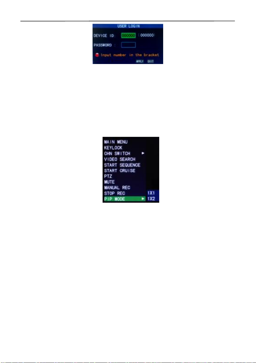
2.3 System Login
The default user code for logging in to the DVR main menu is 000000 without any
password. These should be changed better to provide better security for your DVR
system. To change the code and password, go to Basic Settings→User Password. You
can set the passwords for both ordinary users and the administrator. The administrator
has all the operating privileges, while ordinary users only have limited privileges, being
only able to monitor the video and perform video search and playback of previously
made recordings. After changing the password, any subsequent attempts to enter the
DVR main menu will produce a "User login" interface, as shown below:
Page 11
4 Cameras & 4 Channel DVR Video Security System Bundle
Equipment code: You can enter the equipment code "000000" (displayed on right side)
into the "Device ID" input box. When using the mouse, the default code will be
automatically input into the box for you. When operating multiple DVRs in the same
location, you should change the equipment codes so that the remote control of one
device does not activate the other devices.
2.4 Shortcut Menu
Click the right mouse button anywhere on the interface screen to see a list of quick
operations in the pop-up menu. Left-click a menu option to select it or left click
anywhere outside the menu to clear it from the screen.
2.4.1 Main menu
Click "Main Menu" to enter the main menu interface (please see 3.1).
2.4.2 Lock
When the password function is enabled (please see 2.3) you can lock the system menu.
To do this, right click anywhere on screen to get the pop-up menu then select the
"KEYLOCK" menu option. Until the lock is disabled access to the main menu will
require a password.
2.4.3 Channel switching
An 8-channel DVR can select 8-channel, front 4-channel, and back 4-channel display
modes. A 4-channel DVR can choose 4-channel and 1-channel modes.
2.4.4 Video search
Please refer to Chapter 3
2.4.5 Start Sequence
Start the video channel automatic switching function. (Right-click to exit)
2.4.6 Start Cruise
Starts a preset PTZ "cruise" function (right click to disable cruise mode). Note that this
feature can only be used after a PTZ camera's cruise points have been setup.
Page 12
4 Cameras & 4 Channel DVR Video Security System Bundle
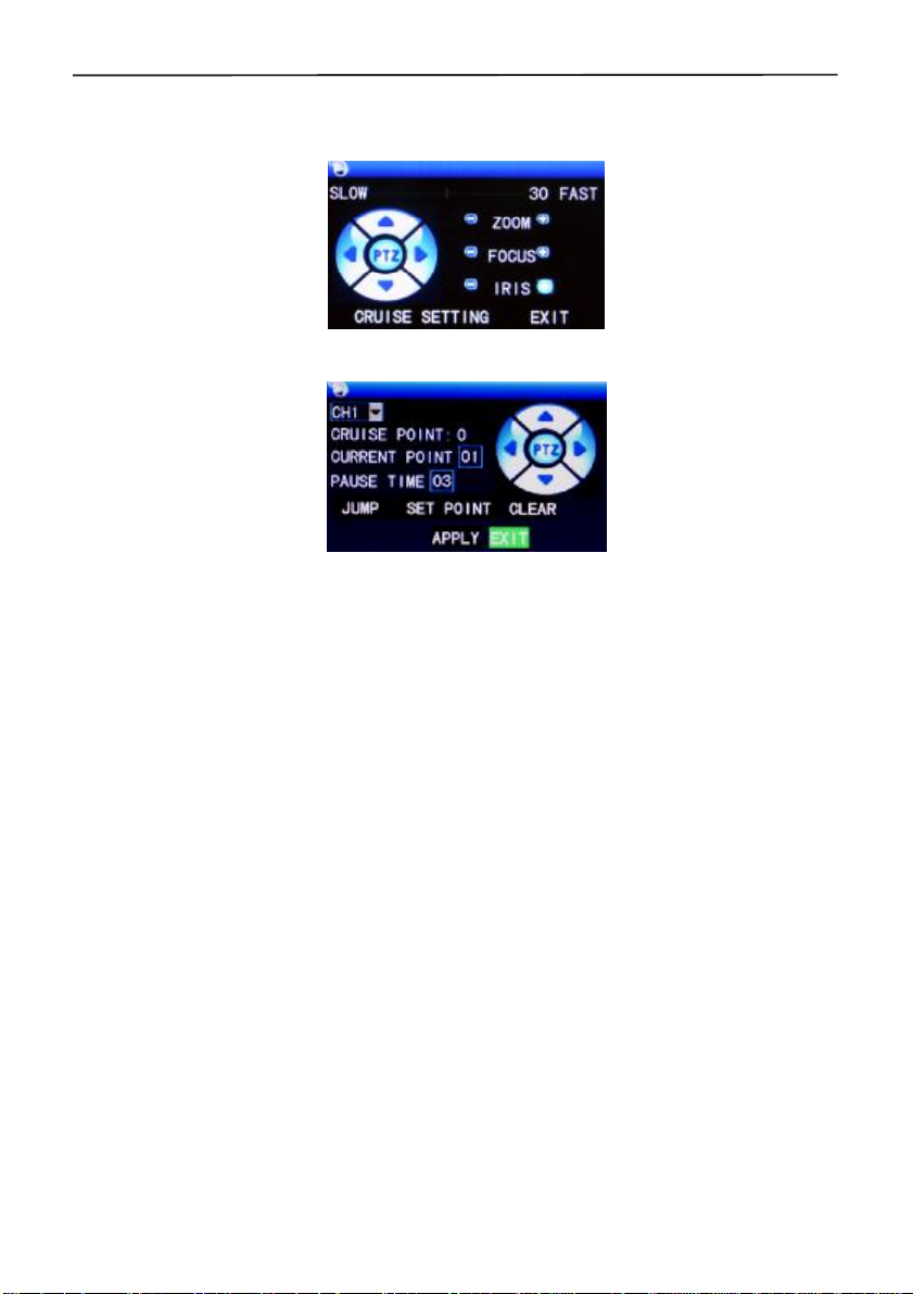
2.4.7 PTZ Control
Right click the mouse in the main interface and select "PTZ control" from the pop-up
menu, producing the following interface:
The PTZ speed (fast or slow) can be controlled in this interface, as well as zoom, focus,
and aperture control.
Cruise setting:
Step 1: Select the PTZ channel.
Step 2: Set the pause time(s).
Step 3: Adjust the arrow keys to the desired camera position.
Step 4: Click "SET POINT". Repeat steps 2-4 to set additional locations.
Step 5: Click "APPLY" to save the settings.
Step 6: Exit to the live screen, right click to get the pop-up menu, and select
"START CRUISE".
Notes:
1. If you need to set up more points, repeat steps 2-5.
2. To view the point has been set, in the current point enter the number, select
"JUMP".
3. To delete the point has been set, enter the number, select delete
2.4.6 MUTE
Select the "MUTE" option to disable audio capture.
2.4.7 Manual recording/stop recording
If "timing record" is enabled (please see Chapter 3) and the preset recording time is not
active, the "manual recording" and "timing record" functions can be selected. When
boot-record mode is enabled, this function is not available.
2.4.9 ZOOM
In the single-channel full-screen mode you can zoom in on a section by left-clicking and
dragging the mouse around the area you want to see in closer detail.
Page 13
4 Cameras & 4 Channel DVR Video Security System Bundle
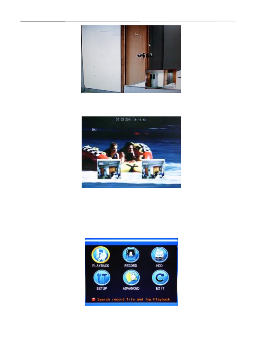
2.4.10 PIP
In the single-channel full-screen mode, you can see floating images of other channels.
Chapter 3 Advanced Settings
3.1 Main Menu
The main menu has the "PLAYBACK", "RECORD", "HDD", "BASIC", "ADVANCED"
and "Exit" options, as shown below:
Note: The settings on all the submenus below the Main Menu will not be active until
"Enter" is selected. Any settings will be lost if the menu is exited without first saving the
settings. When the mouse cursor is placed over a menu item, a "tool tip" indicating the
function of that item is displayed.
Page 14
4 Cameras & 4 Channel DVR Video Security System Bundle
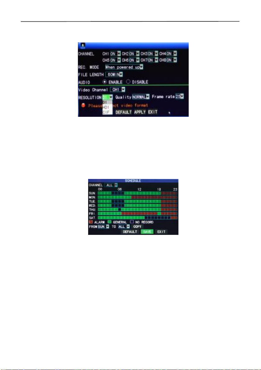
3.2 Recording Mode
Enter the Recording Mode screen by selecting "RECORD" from the Main Menu:
CHANNEL: used to select if the video recording function is enabled for the
corresponding recording channel.
REC MODE: select either startup recording or timer recording.
When powered up: starts recording when the DVR is powered on (only if the
corresponding channel is enabled in the "Channel" option).
BY TIME: performs recording as scheduled. When "timing recording" is selected the
"Record Time Configuration" button will appear on the right. Move the cursor here
and press "Enter" to enter the Record Time Configuration screen, as shown below:
Channel: You may choose either "ALL" or a single channel.
Time configuration: First select from the 3 modes: Alarm Recording, General
Recording, and No Recording as your desired recording mode for a certain
lattice and configure specific recording time lattices (each lattice represents 1
hour). Each lattice can be configured into different recording modes by marking
them in different colors, such as red, green, and the background color, which
represent alarm recording, general recording, and no recording within each hour,
respectively.
FILE LENGTH: Left-click or press "Enter" to select the File length from the 4 options:
15min, 30min, 45min and 60min.
AUDIO: enable or disable audio recording.
RESOLUTION: available in D1(704*576), HD1(704*288)and CIF(352*288)
QUALITY: available in the 3 levels of high, normal, and low, corresponding to the 3
data stream standards of high, normal and low bit rates.
FRAME RATE: adjust the frame rate for the recording.
Page 15

4 Cameras & 4 Channel DVR Video Security System Bundle
3.3 Video Search
Enter the Video Search screen from Main Menu→Video Search, as shown below. This
unit supports 3 video search modes:
A. Timing playback
Time input: First select the corresponding channel and then adjust the date and time
to be searched. Left-click or press "Enter" and the direction keys or enter digits
directly for year, month, date, hour, and minute adjustment, and then click "Playback"
to play back the record of this period of time. For 4-channel DVRs, the 4 channels
can be played back simultaneously.
B. Playback based on record state
Enter the year, month and date to be searched in the "Time Input" box and click
"Search" to view the record state of this date, as shown below:
Month: displays the recording information of every day in the current month. A
green block indicates normal recording, a red block indicates alarm recording, and
the background color indicates no recording. Click a date on this bar to search the
record information of every hour of that day. The search results will be visualized in
the "Day" bar below.
Date: displays the recording hours of the current day. Each lattice represents 1hr
and one recording segment is 0.5hr. The presentation of the record state is the
same as above. Click a 0.5hr segment of a day directly to enter the record
playback of this segment.
C. Playback based on file list
Enter the year, month and date to be searched in the "Time Input" box and click
"Search" to view the record state of this date. Click a certain day on the "Month" bar
then "FILE LIST", and the "FILE LIST" screen will pop up, as shown below:
Channel selection: There are 5 options: 1, 2, 3, 4 and all (9 options for 8-channel
DVR). After selection and confirmation the channel file to be displayed can be
selected in the following list.
Record type: There are 3 options: All, Normal, and Alarm. After selection and
confirmation, the searched message will be displayed automatically as a list, as
shown below:
Page 16

4 Cameras & 4 Channel DVR Video Security System Bundle
Notes:
1. The detailed "FILE LIST" displays previously saved recordings. Each entry
includes which channel the recording was made from, the data and time of the
recording, the physical file size of the recording, and the type of recording (normal
or alarm).
2. Highlight the desired recording file in the list using the up and down cursor keys.
When the desired recording is highlighted, press "Enter" to begin playback of that
recording.
3. If "Record Time Superimposition" has already been enabled on the "Basic Setup"
screen, the playback screen will display the date and time of the recording.
Otherwise, , there will be no clock display on the playback screen.
4. During playback of a recording, press "Slow" for slow play, press "Fast Forward"
or "Fast Backward" for fast forward or backward play, or press "Pause/Frame" for
pause or frame-by-frame playback. Press "Exit" to exit from the playback screen
and return to the menu of the previous level.
3.4 Backup
Before any recordings can be backed up, please attach a USB hard drive or flash drive
to the DVR. Next, enter the "FILE LIST" (see 3.3 Video Search) screen to locate and
select the desired recording file. Move the cursor up and down on the FILE LIST screen
to select a recording file. Move the cursor to the "BAK" checkbox and press enter to
select this recording file for backup. A "√" will appear in the box, indicating that this
recording file has been selected. Now move the cursor to the option box on the right
and click "BACKUP" to begin the backup operation. A progress message dialog will be
displayed, as shown below:
Notes:
1. When the available space of the backup device is less than the size of the
Page 17

4 Cameras & 4 Channel DVR Video Security System Bundle
recording file, the system will prompt the user with a "Not Enough Space"
message.
2. After the recording file has been backed up, remove the backup device.
3. See Chapter 4 "DVR Network" for network backup procedures.
3.5 Hard Disk Management
Enter the Hard disk Management screen from Main Menu→HDD, as shown below:
STATUS: The DVR will automatically check for the proper operation of an installed hard
disk drive. If the hard disk needs formatting, "UNFORMATTED" will be displayed in the
hard disk status display and you can click "HDD Format " to format the hard disk. If the
system detects an available hard disk, the hard disk status will be "ONLINE".
ALL/FREE: Displays the total storage capacity and current remaining storage capacity
of the hard disk.
TIME LEFT: Displays the amount of recording time available on the hard disk, based
on the currently selected video "resolution" and "quality".
FORMAT: Click the check box and a "√" will appear, indicating that this HDD has been
selected for a subsequent format operation.
OVERWRITE: When set to ENABLE, the DVR will automatically overwrite the earliest
recording when it needs more space for new recordings. When set to DISABLE, the
DVR will stop making any new recordings once the hard disk is full.
HDD FORMAT: Before it can be used to store recordings, the hard disk must be
formatted. After checking the FORMAT box (see above), click the "HDD FORMAT"
option to begin the formatting process. A confirmation dialog will be displayed. Click
"ENTER" to begin formatting or "CANCEL" to abort the operation. Once the new hard
disk has been formatted, the DVR will automatically reboot.
USB FORMAT: Formats a hard disk or flash drive attached to the system's USB 2.0
port.
DEFAULT: Restores the factory default values.
3.6 Basic Setup
Enter the Basic Setup screen from Main Menu→Basic:
Page 18

4 Cameras & 4 Channel DVR Video Security System Bundle
The Basic Setup screen includes the 6 options of Language, Date/Time, Password,
Cameras, Video/Audio, and Exit.
3.6.1 System language
Move the cursor to the "LANGUAGE" option (the icon is enlarged and highlighted to
indicate selection) and press "Enter" to enter the language selection screen, as shown
below:
Select the desired language from the list, then click APPLY to save the setting. The
language selection will take effect after the DVR is rebooted.
3.6.2 Time setup
Move the cursor to the "DATE/TIME" option (the icon is surrounded by a yellow frame
to indicate selection) and press "Enter" to enter the setup screen of this option, as
shown below:
The system time, date format, time format, time zone, and DST time can be set up in
this screen.
Page 19

4 Cameras & 4 Channel DVR Video Security System Bundle
3.6.3 User password
DEVICE ID: EIf more than one DVR is being operated in the same area, each should
have a unique Device ID. Enter digits directly to set the DVR ID number.
PASSWORD: Press "Enter" and select "ENABLE" or "DISABLE" to set whether a
password is needed for access or not. If this option is enabled, the user has to enter
his/her password to log in successfully. If it is disabled, the main menu of the system
can be logged in directly without the need for a password.
User Password: This option is operated with keys or the mouse. Enter digits directly to
set the user password.
Admin password: This option is operated with keys or the mouse. Enter digits directly
to set the administrator password.
Notes:
1) This unit has no initial password. When you’re setting up passwords, it is
recommended that the two passwords are set up at the same time. If you forget
your password, please contact Monoprice Technical Support for assistance.
2) Only the locking, channel changeover, video search, log search, backup, PTZ
control, mute, manual recording, and stop recording functions are available to
normal users.
3.6.4 CAMERAS
Move the cursor to the "CAMERAS" option (the icon is surrounded by a yellow frame to
indicate selection) and press "Enter" to enter the setup screen, as shown below:
NAME: Move the cursor to the input box of this option and press "Enter" to enter the
input screen. Numerical, English, and Chinese pinyin input methods are supported.
POSITION: Move the cursor to this option and press "Enter" to change between name
Page 20

4 Cameras & 4 Channel DVR Video Security System Bundle
positions. There are 5 setup options: top left, bottom left, top right, bottom right, and off.
COLOR: Move the cursor to "Setup" of the corresponding channel and press "Enter" to
enter the color setup screen, as shown below:
Press "Enter" or drag the cursor directly to set the picture color, including the 4 options
of chromaticity, brightness, contrast and saturation. Press "Enter" to exit and save the
set parameters.
PREVIEW:
On: The picture of this channel can be seen in the Video Preview screen.
Off: The Video Preview screen of this channel has been shielded, but there is no effect
on the recording of this channel.
PREVIEW TIME: When "On" the system date and time are displayed right above the
Video Preview screen.
RECORD TIME: When "On" a clock is displayed during playback of the current
recording file.
CHANNEL SEQ: Sets the channel sequence time.
3.6.5 VIDEO/AUDIO
Move the cursor to the "VIDEO/AUDIO" option (the icon is surrounded by a yellow
frame to indicate selection) and press "Enter" to enter the setup screen, as shown
below:
Monitor Resolution: Left-click or press "Enter" to set the VGA output resolution to
1280x1024, 1024x768, or 800x600.
CAMERA SYSTEM: Left-click or press "Enter" to select one of the two camera video
systems: PAL or NTSC.
VOLUME SETUP: Move the cursor to "VOLUME SETUP", left-click or press "Enter" to
enter the Volume Setup screen, and press "Left", "Right", or drag the cursor with the
mouse to adjust the volume level.
Note: The system will restart when the VGA resolution or the camera resolution is
modified.
Page 21

4 Cameras & 4 Channel DVR Video Security System Bundle
3.7 Advanced
Enter the following screen from Main Menu→Advanced:
The advanced functions include: Alarm, System Information, Motion Detection (MD),
Mobile Phone Monitoring, System Maintenance, PTZ (pan, tilt, zoom) Setup, and
Network Setup.
3.7.1 Alarm
Move the cursor to the "ALARM" option (the icon is surrounded by a yellow frame to
indicate selection) and press "Enter" to enter the setup screen, as shown below:
I/O CHANNEL and I/O ALARM: Each channel corresponds to an I/O state alarm.
When the alarm input of a channel is triggered, the alarm recording of the
corresponding channel will be started.
NO: Normally on.
NC: Normally close.
OFF: shutdown alarm of this channel.
Note: When an alarm is produced, a red letter "I" will be displayed above the
corresponding channel.
HDD LOSS: When set to "On", if the system cannot identify the hard disk, an alarm will
be generated, and a red letter "H" will be displayed at the bottom left corner of Channel
1 in the lower part of the Video Preview screen.
HDD SPACE: When set to "On", if the remaining space of the hard disk is less than
500MB, the lower part of the Video Preview screen will display: "The space of the hard
disk is not enough. Please change the disk after shutdown."
VIDEO LOSS: When set to "On", if the video of a certain channel is lost, this channel
will display in the lower part of the Video Preview screen: "Video Loss".
ALARM MANAGE OUTPUT: The length of time that the DVR will output the alarm
signal once an alarm has been triggered. Options are 0, 10, 20, 40, and 60 seconds.
Page 22

4 Cameras & 4 Channel DVR Video Security System Bundle
BUZZER: The time of the buzzer will ring once an alarm has been triggered. Options
are: 0, 10, 20, 40, and 60 seconds.
Post Alarm Recording: The length of time to wait before beginning recording after the
motion detection alarm has been triggered. Options are: 30 seconds, 1 minute, 2
minutes, and 5 minutes.
Email SETUP: The DVR can send an email whenever the motion detection alarm is
triggered. For this to occur, the DVR must be connected to internet (see Chapter 4
"DVR Network" for instructions). When motion detection is triggered, the system will
extract a still image at the time of the trigger and will send it to the specified email
address. Use this screen to setup your email parameters.
SSL: A secure link transmission protocol. Whether this is "On" or "Off" is determined by
the mail server.
SMTP PORT: The outgoing port on which mail will be sent. This is usually port 25, but
other servers, such as GMail, use different values (GMail uses port 465). Check with
your ISP if you have difficulties with this.
SMTP: The server address of the mailbox used to send the email. For example, the
SMTP server of the Yahoo mailbox is smtp.mail.yahoo.com. Check with your email
provider if you are unsure of the value for this field.
SEND EMAIL: The mailbox address used to send emails.
SEND PW: The password of the mailbox used to send emails.
RECV EMAIL: The email address used to receive the picture transmitted by the DVR
motion detection alarm. If the alarm frequency of the system is high, the number of
pictures sent will also be larger. Please pay attention to the available space of your
mailbox to ensure that it does not get filled with alarm images.
3.7.2 System info
Enter the System Info screen from Main Menu→Advanced Functions, as shown below:
Page 23

4 Cameras & 4 Channel DVR Video Security System Bundle
You can see the software version number, whole unit version number, MAC address,
and DVR serial number on this screen.
3.7.3 Motion detection
Enter the Motion Detection screen from Main Menu→Advanced, as shown below:
MD Channel and STATUS: Each channel has a corresponding switch to determine if
the motion detection is active or not. Press "Enter" to select motion detection "On" or
"Off".
SENSITIVITY: Each channel has a corresponding sensitivity setting (1, 2, 3, or 4), in
which 4 is the most sensitive to any motion detected. Press "Enter" to toggle the option.
MD AREA: Each channel has a corresponding motion detection area setting in which it
will look for motion, while ignoring the rest of the viewing area. Move the cursor to
"SETUP" option of the corresponding channel and press "Enter" to enter the motion
area setup screen. On this screen a red block indicates that motion detection is
activate for that area and a transparent block indicates that motion detection is not
activated, as shown in the example below:
Operating prompt:
Remote control operation: Use " " (display mode) to select full screen or blank;
Mouse operation: Left-click the mouse and drag the motion box to set the area of
dynamic detection.
Motion detection setup procedures:
A. Turn "On" the corresponding channel in the "Channel Status" option.
B. Set the sensitivity level as necessary, usually set at 3 or 4.
C. Set the motion area of the corresponding channel in the "Area Setup" option.
D. In the "Recording Mode" screen, set the corresponding channel to "On" in the
"Channel" option.
E. In the "Recording Mode" screen, select "Timing Recording" in the "Recording
Mode" option and click "Record Time Configuration" to enter the Record Time
Page 24

4 Cameras & 4 Channel DVR Video Security System Bundle
Configuration screen to set the times at which alarm recording will be possible
(see timing recording in "Recording Mode" for the setup instructions).
After the setup has been completed and motion detection is triggered, a red letter "M"
will appear in the screen of the appropriate channel. See "Alarm processes" in Section
3.6.1 for alarm processing options.
3.7.4 Mobile phone monitoring
The mobile phone monitoring function of this DVR is supported by mobile phones using
the Windows Mobile and Symbian operating systems, such as the Dopod P660,
Nokia N78, and Nokia 95.
Enter the following screen from Main Menu→Advanced Functions→Mobile Phone
Monitoring:
Mobile Username and Password: Set the cell mobile login user name and password.
The default values are empty.
Service port: Set within the range 1,024 - 65,535. This port must be mapped on the
router and its setup method is the same as the mapping method of the port in network
setup.
For more detailed mobile phone installation and user manual, please refer to the
Mobile Phone User Manual on the CD.
3.7.5 System maintenance
Enter this screen from Main Menu→Advanced, as shown below:
AUTO RESET: When this option is set to "On", you can determine the reboot
frequency for the DVR.
System update: Copy the update file to the root directory of a USB harddisk/flash drive
Page 25

4 Cameras & 4 Channel DVR Video Security System Bundle
then insert the disk into the USB 2.0 port on the back of the DVR. Click the "Enter"
button to begin the system update process. The screen will display a progress box
until the update is completed. The system power should not be interrupted during the
update process.
DEFAULT SETTING: Restores the system parameters to the factory default settings.
RESTART: Restarts the DVR.
3.7.6 PTZ
Enter the "PTZ" screen from Main Menu→Advanced, as shown below:
CHANNEL: Select the channel number of the camera you want to control. If using the
eight-channel DVR, click the "NEXT PAGE" button to see the second 4 channels.
PROTOCOL: Select the protocol used by the PTZ camera by selecting the brand and
model of camera. The default is Pelco-D.
BAUD RATE: Select the data transfer rate used by the camera: 1200, 2400, 4800, or
9600.
DATA BIT: Select the number of data bits in each transfer packet: 5, 6, 7, or 8.
STOP BIT: Select the number of stop bits in each packet: 1 or 2.
VERIFY: Select the type of data verification used: None, Odd, Even, Mark, or Space.
ADDRESS: Complete the PTZ code of the corresponding channel.
Note that you only need to set the Protocol, Baud rate, and Address code if all you
need to do is to set the PTZ of the attached camera.
See Shortcut Menu→PTZ Control for PTZ control information.
3.7.7 Network setup
Enter the "Network" screen from Main Menu→Advanced, as shown below:
Page 26

4 Cameras & 4 Channel DVR Video Security System Bundle
TYPE: Select the type of network setup in use: static configuration, DHCP, and
PPPOE.
Static: Allocates an IP address manually.
DHCP: Automatically acquires an IP address from the DHCP server.
Note: After selecting the DHCP mode and receiving confirmation of the
change, restart the system. After startup, the DVR will establish a connection
with the DHCP server automatically. When this is successful the DVR will be
allocated an IP address, which will be displayed on the screen.
PPPOE: Uses a broadband dial-up network access method, as shown below:
PPPOE NAME and PASSWORD: Enter the user name and password provided to you
by your ISP.
When using an ADSL modem, you can connect it directly to the DVR. If you do so,
select "Internet Connection" for the PPPOE mode. Press "Enter" on the PPPOE
selection in the connection mode to enter the PPPOE Setup screen. After entering the
broadband user name and password, click "Enter" and the system will restart. After that,
the DVR will automatically establish a network connection using the PPPOE mode.
After a successful connection, the IP address will automatically be modified to the
acquired dynamic WAN IP address.
MEDIA PORT: Input the port number used for the private protocol communications
between the DVR and the PC (usually 9000). If this port is occupied by any other
service, modify it to an unused port.
WEB PORT: Input the http port (default = 80). If the administrator modifies the WEB
port to any other port, such as 88, you will need to add the port number to the IP
address (for example: "http://192.168.1.19:88") in the address bar when accessing the
DVR via Internet Explorer.
IP address: Allocate an IP address, depending on the network environment of the
DVR.
Subnet mask: Enter a subnet mask depending on the network environment of the
DVR.
Gateway: Set the gateway, depending on the network environment of the DVR. If there
is no router device in the network, please allocate an IP address on the same network
segment. If there is a router device in the network, you will need to set the
corresponding gateway.
DNS: Set the IP address of the domain name server (DNS varies from city to city). You
can use the same domain name server as you use for your PC.
UPNP: When the UPNP function is on the DVR will map the port and IP into the router
Page 27

4 Cameras & 4 Channel DVR Video Security System Bundle
automatically.
DDNS Setup
Click "DDNS Setup" to enter the following screen:
DDNS: When a domain name resolution server is available, please select DDNS "ON";
SERVICE: Select one of three DDNS server options: 3322, dyndns, and perfecteyes.
Host name: Enter the host name registered on the dynamic domain name server.
User name: Enter the user name registered on the dynamic domain name server.
Password: Enter the password registered on the dynamic domain name server.
3.8 Domain Name Application
1) Create account
Go to www.dyndns.com and click the Create Account option. Fill in the account
information:
After confirmation, the system will inform you that a verification message has been sent
to the designated mailbox, as shown below:
Page 28

4 Cameras & 4 Channel DVR Video Security System Bundle
2) Activate account
Log into your mailbox and open the confirmation link sent from support@dyndns.com,
as shown below:
Click the link below and enter the website to activate the account.
3) Login
After successful activation, open the home page http://www.dyndns.com/ to log in. After
successful login, click Services→Dynamic DNS, as shown below:
4) Application for free domain name
After entering the "Dynamic DNS Services" screen, click "Dynamic DNS Free" to apply
for a free dynamic domain name, as shown below:
Page 29

4 Cameras & 4 Channel DVR Video Security System Bundle
Enter the "Dynamic DNS Free" screen, as shown below. Click the "Get Started" button.
Enter the hostname, select the service type, and then enter the dynamic IP address
(usually being the dynamic IP address of the network of the DVR host) to be tied in the
"Add New Hostname" screen, as shown below. Complete the application for the
dynamic domain name as prompted.
Page 30

4 Cameras & 4 Channel DVR Video Security System Bundle
Page 31

4 Cameras & 4 Channel DVR Video Security System Bundle
3.9 Port Forwarding
Port forwarding procedures:
1) Set the host IP address. See the relevant section.
2) Log into the router.
Assuming the IP address of the router is 192.168.1.1, type this address into the IE
address bar and press "Enter". A login prompt box will appear, as shown below:
Click "Enter" to enter the main screen of the router, as shown below:
Click "Applications & Gaming ", as shown below:
Page 32

4 Cameras & 4 Channel DVR Video Security System Bundle
As shown above, fill in the IP and the port number in the corresponding files, and select
"Both" in the "Protocol" column. The check mark in the "Enable" column indicates that
the entry is active. After setup, click "Save Setting" to save the settings.
Note that 80 is the WEB port, 9000 is the media port, and 15961 is the mobile phone
port. All these ports can be modified in the menu, please check the ports on the DVR.
Page 33

4 Cameras & 4 Channel DVR Video Security System Bundle
click
•
click
ƒ
Input IP
click
Chapter 4 DVR Network
4.1 Functional Characteristics
The DVR supports LAN and WAN access, as well as IP and domain name access.
4.2 Installation and Download of Controls
Automatic installation of plug-ins unit:
First add the IP address of the DVR as a reliable site for your system. For example, if
the IP address of the DVR is 192.168.1.100, first open IE Attributes→Internet Options
→Security Options for an ordinary XP system, as shown below. This can be set in 9
steps.
②click
④cancel the optional
⑦
⑧ All selected "Enable"
⑨
Note: Enter the IP or Domain Name in the
third step without a port number.
After setup, enter the IP address in the IE address bar, and complete the automatic
installation of the plug-in unit as prompted.
4.3 IE Login
Log into the system after the plug-in unit has been installed. For example, if the domain
⑤
⑥
Page 34

4 Cameras & 4 Channel DVR Video Security System Bundle
name of the DVR is dvrtest05.eicp.net and its port is 80, enter the domain name in the
IE address bar. Enter the user name and the password, select "LAN" or "INTERNET"
depending on the network environment, and click "Login" to log into the client end or
access the DVR end remotely.
Note: If the DVR host is in a LAN, but you have chosen the "WAN" option, the preview
image will be non-real-time.
4.4 Real-Time Preview
After logging into the client end successfully, enter the real-time preview screen directly
and obtain a video connection automatically, as shown below:
Play control:
: open or close the image; : capture; : remote recording (see "System Setup"
for setting the storage directory); : divide the screen into 1, 4, 9 and 16
parts respectively;
PTZ control: controls the upward, downward, leftward, and rightward motion of the
PTZ remotely, as well as the zooming, focusing, aperture control, and preset points of
the lens.
Page 35

4 Cameras & 4 Channel DVR Video Security System Bundle
4.5 Recording Playback
Click "PLAYBACK" to enter the Recording Playback screen, as shown below:
First select the date of the recording to be played and the channel and recording types,
then click "Search". The eligible recording files will appear in the file list, with the bold
numbers denoting dates with recording data, as shown in the figure above. Select the
file to be played back and double-click the filename or click "Playback" to play it. A
control bar will appear at the bottom of the screen for pause, stop, fast forward, slow
play, and next frame control. Click "Backup". This file will be saved in the designated
directory (see Figure 4.10 for setting the save directory).
4.6 Recording Mode
Click Setup→RECORD to enter the remote recording mode, as shown below:
The setup method is the same as the main DVR menu. See "Recording Mode" in
Chapter 3 for details.
Note: "Detail" can be set on 4-channel DVRs only.
Page 36

4 Cameras & 4 Channel DVR Video Security System Bundle
4.7 Alarm Setup
Click Setup→Alarm to enter the Alarm Setup screen, as shown below:
The setup method is the same as the main DVR menu. See "Alarm Setup" in Chapter 3
for details.
4.8 PTZ Control
Click Setup→PTZ to enter the PTZ Control mode, as shown below:
See Chapter 3 "Network Setup" in this manual for setup instructions.
.
4.9 Network Setup
Click Setup→Network Setup to enter the Network Setup screen, as shown below:
Page 37

4 Cameras & 4 Channel DVR Video Security System Bundle
See Chapter 3 "Network Setup" in this manual for the setup method.
4.10 System Setup
Click Setup→Setting to enter the Setting screen, as shown below:
INTERNET: Set the code stream. The higher the code stream is, the clearer the remote
image will be, but the network bandwidth must be high to accommodate the extra data
or the image may be delayed.
File SAVE PATH: Set the directory into which recordings will be saved during remote
recording and remote backup operations.
IE password: Set the IE login password. (Note: This password may be cleared in the
main menu of the DVR.)
4.11 Host Info
Click "DVR HOST" to enter the Host Info screen, as shown below. View the operating
state of the hard disk, the time remaining and the software version and MAC address of
this system.
Page 38

4 Cameras & 4 Channel DVR Video Security System Bundle
Chapter 5 Client Software & Player
5.1 Client Software
Insert the software disc into the drive on your PC. Double click the "Setup" icon to begin
the software installation. Continue to install the software by following the instructions in
the setup program. Once installed, a User Login dialog is displayed, as shown below:
IP ADDRESS:Enter IP address or Domain Name.
MEDIA PORT:Enter the port number (the default is 9000).
PASSWORD:Enter your IE password.
NETWORD:Select one of two web styles: LAN or INTERNET.
Note: After the successful login in, the interface is the same as that of IE. Please
refer to the instructions in Chapter 4.
5.2 Video Player
Open the PLAYER installation program PlaybackSetup.exe on the CD disk. Follow the
installation instructions. Once installed, double-click the program icon to start the
program, as shown below:
Page 39

4 Cameras & 4 Channel DVR Video Security System Bundle
Click "File" as shown in the following image. Select "Open Local File":
Select the .264 file type, as shown in the following image:
Select the file you want to play. Click "OPEN", as shown in the following image:
Page 40

4 Cameras & 4 Channel DVR Video Security System Bundle
Click the "PLAY" option, as shown in the following image:
After clicking the "'PLAY" option, click the "up arrow" button in the player to enter the
screen shown in the following image:
Page 41

4 Cameras & 4 Channel DVR Video Security System Bundle
Function
Function
①
Definition
Icon
①
Play Forward, Play backword
Pause, STOP ST Start Operation
Backward /forward frame
<< >>
Next Hour
Note:1. Double click the image to enlarge it.
Audio Setup:
Click SETTING→AUDIO CHANNEL SETUP→Normal Video Bar, as shown in the
following image:
Recording Schedule
Slow/Normal/Fast
Capture bitmap
Decrease video
2. When converting the AVI format, you should click the ST button. Then click AVI
to select the time periods
Icon
avi
Definition
All video
Increase video
File Cut
File Deletion
AVI Format transmission
OSD
Volume Control
Page 42

4 Cameras & 4 Channel DVR Video Security System Bundle
Select the channel audio to be played then click "OK", as shown in the following image:
Page 43

4 Cameras & 4 Channel DVR Video Security System Bundle
Appendix 1 Q&A
1. I lost my password, how can I recover it?
A: Please contact Monoprice technical support for assistance. To prevent this from
happening, please use a password that is easy to remember and/or keep a copy of
the password in a safe place.
2. I have no video output signal?
A: Please confirm that the video output port is connected to the VIDEO OUT, and
ensure the BNC connectors are in good connection. Check that the BNC cable in
use is not too long or worn out. Ensure N system/P system selection is correct.
3. The system can not detect the hard disk?
A: If the system can not detect the hard disk, please confirm that hard disk data
and power cables are properly connected. Try disconnecting the cables and then
reconnect them. Confirm that the power adaptor is DC12V 3A (the range is
3A--5A). Note that Seagate brand hard disks are recommended.
4. What is the affect to other equipment from the DVR's heat?
A: The DVR will produce a certain amount of heat during operation. Please install
the DVR in a safe place with good ventilation to keep temperatures as low as
possible and ensure long operating life of the unit.
5. How much recording time can be put onto a 1TB hard disk by a 4-channel or
8-channel DVR?
A: Please refer to Appendix 2 "hard disk space calculation".
6. The DVR’s remote controller doesn't work, but the monitor screen is correct and
the panel buttons can be used properly?
A: Check the batteries in the remote control. Ensure that the remote is pointing to
the IR receiver on the DVR and that the IR receiver is not blocked or obscured.
7. The "Manual recording" and "Stop recording" functions on the front panel and
shortcut menu do not work?
A: These function will only work when the system is not actively performing a timed
recording.
8. Is playback available while recording? Is multi-channel playback available?
A: Yes, this system can support playback while recording. The 4-channel DVR can
support 4 channels playback at the same time, but th 8-channel DVR can only
support single channel playback.
9. Can I delete recording files from the DVR hard disk?
A: For security reasons you cannot delete individual recordings from the hard disk.
If it is necessary, you can format the hard disk.
10. The E-mail alert is not functioning?
A: Please perform the setup again, making sure to follow the instruction exactly.
Check for any typographical errors or extra spaces. Check the mail server's
functionality to ensure the server is operating.
11. Cannot locate any recordings for playback?
A: please check the hard disk data cable connection to ensure it is properly
connected. Check to ensure that the system time is properly set.
12. DVR can not control the PTZ after setup?
Page 44

4 Cameras & 4 Channel DVR Video Security System Bundle
A: Please test for the following reasons:
u The RS485 cable A at B.
u PTZ decoder setting, connection and installation is incorrect.
u PTZ incorrect setup in the DVR.
13. Motion detection does not work?
A: Check the motion detection time and motion detection zone to make sure that
they are properly configured. Check the sensitivity setting.
14. The alarm does not work?
A: Check the alarm setting and alarm connection. Ensure that alarm signal input is
correct.
15. The DVR cannot obtain real-time access to LAN?
A: When accessed through the LAN the 8-channel DVR can show real-time
images only when the network environment is set to "LAN" in the login interface.
For 4-channel DVRs, in addition to selecting "LAN" in "network environment"
option in login interface, please select "ordinary" in the "details" option under
recording mode.
16. The remote login interface is available, but shows "Login failed" when I try to
login?
A: 1) Please check whether the password is properly set. If you forgot the
password, enter the "User Password" interface of the DVR and click "Clear IE
Password", then login again. 2) Please check the DVR's local network and remote
access network. Slow network speeds will cause a failed login. Please try it again
several times.
17. After successful remote access, shows "user is configuring…. "?
A: Please exit all DVR menus and keep the preview status showing. Remote setup
is now vailable and storable.
18. There is smearing on the screen during real-time monitoring or sometimes even a
short pause?
A: 1) It is normal if it occurs for less than 10 seconds; 2) Confirm that the DVR
environment network speed is guaranteed.
19. Serious image delay during cell phone monitoring?
A: 1) Change the mobile wireless network into 3G or WIFI; 2) Confirm the DVR
environment network speed is guaranteed; 3) Do not put cell phone in a weak
signal area; 4) It’s normal if less than 10 seconds.
Page 45

4 Cameras & 4 Channel DVR Video Security System Bundle
Appendix 2 Hard Disk Space Occupation Calculation
This DVR stores data on the hard disk as shown in the following table.
Unit of Measure: Megabytes/Channel/Hour
Bit rate
Resolution
D1 400 300 200
half-D1 350 250 150
CIF 300 200 100
This table is for reference only. Variations in the options and settings can cause more
or less data to be used during recording. Actual results will vary from the above.
Excellent Good Ordinary
Appendix 3 Topology
Page 46

4 Cameras & 4 Channel DVR Video Security System Bundle
▲ Nothing contained in the manual attached to this product shall be duplicated,
disseminated, transcribed or stored in any retrieval system or translated into
any other language without written consent.
▲ The product specifications and information contained in this manual are for
reference only, and the contents thereof are subject to updating without
notice.
▲ We assume no responsible for any damage arising from the improper use of
this product. The product names mentioned in this manual are intended for
identification only, and may also be registered trademarks or copyrights
owned by other companies.
▲ The product color provided in this marketing package may differ from the
color shown on the original package. The pictures are for reference only. The
technical specifications are subject to change without notice. The accessories
available may differ from market to market. Please consult your local dealer.
▲ This manual has been checked carefully but any spelling or technical error is
not precluded. Such error or omission will be corrected in the new version.
We have the right to modify any and all information contained in this manual
without notice.
 Loading...