

Page 1
Maint ena nce
• Check t hat t he br ack et is s ecure and sa fe to u se at r egu lar intervals (at l eas t eve ry three months ).
• Pleas e con tac t you r dealer if you hav e any q ues tio ns.
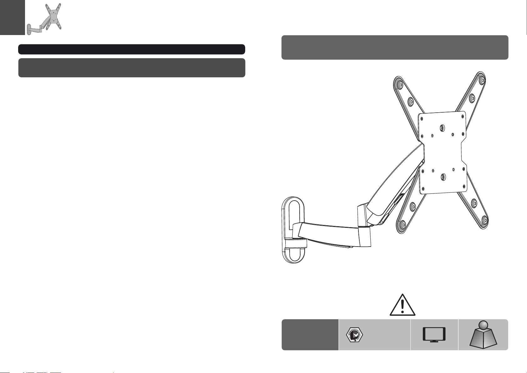
INSTALLATION INSTRUCTIONS
Counterbalance Full Motion LCD Wall Mount
LDA08 -44 2
100x1 00/ 200 x10 0
200x2 00/ 400 x20 0
300x3 00/ 400 x40 0
CA UTI ON : DO NO T EXC EED M AXI MUM
LISTE D WEI GHT C APAC ITY. SE RIO US
INJURY O R PRO PER TY DA MAG E MAY
OCCUR !
47"
MAX
2.5 ~20kg
2.5 ~20kg
2.5 ~20kg
(5. 5~44l bs)
(5. 5~44l bs)
(5. 5~44l bs)
ISSUED: MAR. 2012
Page 2
NOTE: Rea d the entire instr uction manual be fore you st art ins tallati on and as sembly.
WARNING
• Do not begin the installation until you have read and understood the instructions
and warnings contained in this installation sheet. If you have any questions
regarding any of the instruction or warning, please contact your local distributor.
• This mounting bracket was designed to be installed and utilized ONLY as
specified in this manual. Improper installation of this product may cause damage
or serious injury.
• This product should only be installed by someone of good mechanical ability,
with basic building experiences and fully understanding of this manual.
• Make sure that the supporting surface will safely support the combined load of
the equipment and all attached hardware and components.
• If mounting to wood wall studs, make sure that mounting screws are anchored
into the center of the studs. Use of a stud finder is highly recommended.
Component Checklist
IMPORTANT: En sure that y ou ha ve re cei ved all par ts ac cor din g to the comp one nt ch eck list prio r to in sta lli ng. I f
any p art s are m iss ing or faulty, te lep hone your l oca l dis tri butor for a r epl ace men t.
M6 (x8)
B
VESA ada pto r (x )C2 VESA ada pto r (x )D2
Package M
M4x14 ( x4)
M-A
artic ula ted a rm as sembly
A
M4x25 ( x4)
M-B
M5x14 ( x4)
M-C
M5x25 ( x4)
M-D
M6x14 ( x4)
M-E
• Always use an assistant or mechanical lifting equipment to safely lift and position
equipment.
• Tighten screws firmly, but do not over tighten. Over tightening can damage the
items, greatly reducing their holding power.
• This product intended for indoor use only. Using this product outdoors could
lead to product failure and personal injury.
M6x25 ( x4)
M-F
D8 (x4)washe r
M-J
Package W
M8x15 ( x4)
ø14xø 6x1 0 (x4 )
M-K
ST6.3 x55 ( x3)
W-A
M-G
ø15xø 8x1 5 (x4 )
M-L
M8x30 ( x4)
M-H
3mm allen key (x1)
M-M
concr ete a nch or (x 3)
6mm allen key (x1)
W-B
D (x4)5 washe r
M-I
M-N
21
Page 3

1. Disassemble VESA Plate from Wall Mount
3a. Mount on Wood Stud Wall
55mm
55mm
55mm
(2.2")
2.2"( )
(2.2")
ø 4.5mm
(ø 3/16")
1
2
3
Drill pilot holes
· Loose n the u ppe r nut ,
· Remov e the l owe r fla t nut.
2. Remove the Decorative Covers
Remov e VES A plat e.
√
W-A
X X
Screw the wall
mount onto
the wall
WARNING
• Make sure that mounting screws are anchored into the center of the studs. Use of a stud finder
is highly recommended.
• Installers are responsible to provide hardware for other types of mounting situations.
• Installer must verify that the supporting surface will safely support the combined load of the
equipment and all attached hardware and components.
3
4
Page 4

3b. Mount on Solid Brick and Concrete Block
60mm
60mm
60mm
(2.4")
2.4"( )
(2.4")
ø 10mm
(ø 3/8")
4. Install Decorative Covers
1
2
Drill pilot holes
W-B
√
W-A
X X
Screw the wall
mount onto
the wall
WARNING
• When installing wall mounts on cinder block, verify the actual concrete thickness is at least
1-3/8" (35 mm) for using the concret e anchors. Do not drill into mortar joints! Be sure to
mount in a soli d part of the block, generally 1" (25mm) minimum from the side of the block.
It is suggested electric drill on slow setting is used to drill the hole instead of a hammer drill
to avoid breaking out the back of the hole when entering a void or cavity.
5. Assemble VESA Adaptors
5a VESA 300x300, 400X400
5b VESA 400x200
Unit: mm
Unit: mm
B
0
40
0
30
0
0
4
4
00
3
0
0
2
0
0
• Installer must verif y that the supp orting sur face will safely support the combined load of the
equipment and all attached hardware and components.
65
Page 5

6. Install VESA Plate
6-1 For Flat Back Screen
7. Hook the TV onto the Wall Mount
TV
M-A/M -C
M-E/M -G
M-I/M -J
6-2 For Recessed Back Screen
TV
M-B/M -D/ M-F
M-I/M -J
M-K
TV
TV
TV
Screw t he VE SA pla te on to the TV.
Tig hten all screws b ut do n ot ov er
tight en.
TV
4mm
Loose n the u ppe r fla t nut spacing
4mm to VE SA pla te.
Hook the TV onto the wall mount
M-J
M-L
or
M-H
· Level t he TV.
· Place t he lo wer f lat n ut and tighten bo th nu ts.
87
Page 6

8. Tension Adjust
10. Adjustment
M-N
Please keep th e arm level during tension adjustment. Use a proper Alle n key, slightly loos en or tighten the
adjustment s crew according to the display weight.
If display set tles on its own, then rotate adjustment screw towards the "+ " symbol.
If display ris es on its own, then rotate adjustment screw towards the "-" sy mbol.
9. Cable Management
M-M
18 0°
Tig hte n scr ew till the displ ay an gle c an be f ixed.
18 0°
+3° -3°
+15°
-15°
18 0°
max33 5mm
heigh t adj ust abl e
FOLD 3
R
HEC
T
A
T
C
DUS
Connect the ca bles to the display, and press cable cover
inward to rout e the cables through the space.
Note: Leave sl ack in cable for cantilever arm movement.
9
Adjus t to th e des ire d location or til t.
10
 Loading...