

Page 1

Maintenance
• Check that the bracket is secure and safe to use at regular intervals(at least every three months).
• Please contact your dealer if you have any questions.
11
PID 9 7 4 4
Page 2
NOTE : Read th e entir e instr uctio n manua l befor e you sta rt inst allatio n and ass embly.
WARNING
• Do not begin the installation until you have read and understood the instructions
and warnings contained in this installation sheet. If you have any question
regarding any of the instruction or warning, please contact your local distributor.
• This mounting bracket was designed to be installed and utilized ONLY as
specified in this manual. Improper installation of this product may cause damage
or serious injury.
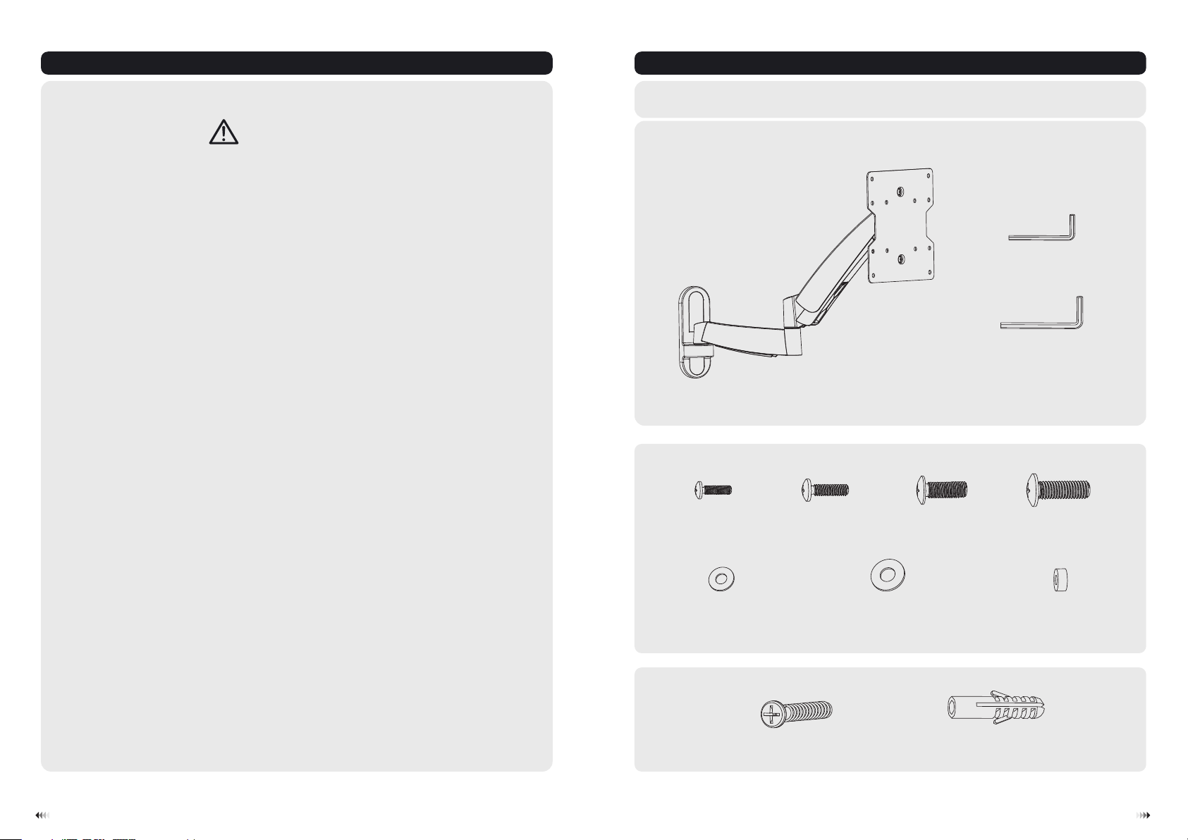
Compo nent Chec klist
IMPO RTANT: Ensu re t ha t you h av e re ce ived al l pa rt s accor di ng t o the com po ne nt chec kl is t pr ior t o in st al ling. I f
any p ar ts a re m issin g or f au lty, tel ep hone yo ur l oc al dist ri bu tor for a r ep la cemen t.
3mm Allen key (x1)
B
• This product should only be installed by someone of good mechanical ability,
with basic building experience and fully understanding of this manual.
• Make sure that the supporting surface will safely support the combined load of
the equipment and all attached hardware and components.
• If mounting to wood wall studs, make sure that mounting screws are anchored
into the center of the studs. The use of a stud finder is highly recommended.
• Always use assistant or mechanical lifting equipment to safely lift and position
equipment.
• Tighten screws firmly, but do not over tighten. Over tightening can damage the
items, greatly reducing their holding power.
• This product is intended for indoor use only. Using this product outdoors could
lead to product failure and personal injury.
Pack age M
M4x14 (x4)
D5 washer (x4)
Pack age W
articulated arm assembly
M-A
M-E
A
ST6.3x55 (x3)
W-A
M5x14 (x4)
M-B
D8 washer (x4)
M-F
M6x14 (x4)
M-C
concrete anchor (x3)
6mm Allen key (x1)
C
M8x20 (x4)
M-D
small spacer (x8)
M-G
W-B
21
Page 3

1. Separate VESA Plate from Wall Mount
3a. Mount on Wood Stud Wall
55mm
55mm
55mm
(2.2")
2.2"( )
(2.2")
ø 4.5mm
(ø 3/16")
· Loosen the upper nut,
· Remove the lower flat nut.
2. Remove the Decorative Covers
Remove VESA plate .
W-A
1
Find and mark the
2
exact location of
mounting holes
3
Drill pilot holes
√
X X
Screw the wall
mount onto
the wall
WARNING
• Make sure that mounting screws are anchored into the center of the studs. The use of a stud
finder is highly recommended.
• Installers are responsible to provide hardware for other types of mounting situations.
• Installers must verify that the supporting surface will safely support the combined load of the
equipment and all attached hardware and components.
3
4
Page 4

3b. Mount on Solid Brick and Concrete Block
W-B
W-A
60mm
60mm
60mm
(2.4")
2.4"( )
(2.4")
√
ø 10mm
(ø 3/8")
1
Mark the exact
Mark the exact
Mark the exact
location of
location of
location of
mounting holes
mounting holes
mounting holes
2
Drill pilot holes
X X
4. Install Decorative Covers
Screw the wall
mount onto
the wall
WARNING
• When installing wall mounts on cinder block, verify the actual concrete thickness is at least
1-3/8" (35mm) for using the conc rete anchors. Do not drill into mort ar joints! Be sure to
mount in a solid pa rt of the block, generally 1" (25mm) minimum from the side of the block.
It is suggeste d electric drill on slow setting be used to drill the hole instead of a hammer dri ll
to avoid break ing out the back of the hole when enterin g a void or cavity.
• Installers must verify that the supporting su rface will safely support the combined load of the
equipment and all attached hardware and components.
5. Install VESA Plate
Top of TV
65
Page 5

6. Hook the TV onto the Wall Mount
TV
TV
TV
TV
4mm
M-A/M-B
M-C/M-D
M-E
M-F
or
Loosen the upper nut spacing
4mm to VESA plate.
Hook the TV onto the wall mount
M-D
M-F
M-G
Screw VESA plate onto the TV.
Tig ht en a ll s cr ew s bu t do n ot o ve r ti gh te n.
M-D
M-F
M-G
M-G
· Level the TV.
· Place the lower flat nut and tighten both nuts.
87
Page 6

7. Tension Adjust
9. Adjustment
Tig ht en s cr ew t il l th e di sp la y an gl e ca n be f ix ed .
B
18 0 °
C
Please tighten socket set screw if the
joints make popping sounds in use.
Please keep the arm level during tension adjustment. Use a proper Allen key to slightly loosen or tighten the
adjustment screw according to the display weight.
If display settles on its own, rotate adjustment screw towards the "+" symbol.
If display rises on its own, rotate adjustment screw towards the "-" symbol.
8. Cable Management
DUS
Connect the cables to the display, and pr ess ca ble co ver in ward t o rout e
the cables through the space.
Note: Leave slack in cable for cantilever arm movement.
9
+3° -3°
+15°
-15°
18 0 °
18 0 °
max335mm
height adjustable
FOLD 3
R
HEC
T
A
T
C
Adjust to the desired location or tilt.
10
 Loading...