

Page 1
safet y scr ew
M-J
fig. 4.1
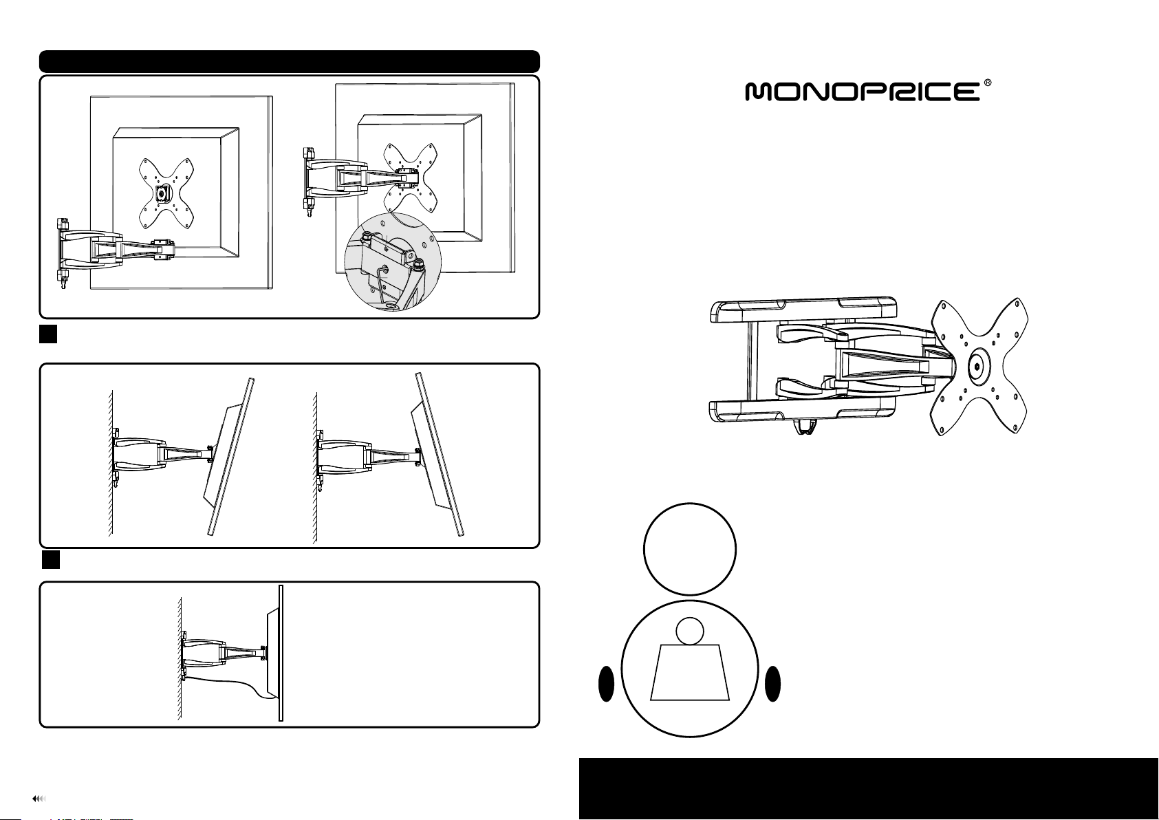
Pitching Angle Adjus tment
5
Push or pull from the top or botto m of th e dis pla y to th e des ired angle , the p itc hing angle can be adju ste d
between -15°~ 15° , swivel: 100° as show n in fi g. 5. 1.
INSTALLATION INSTRUCTIONS
fig. 5.1
Cable Management
6
Route the cables thr ough the cable clip as shown in f ig.6.1.
fig. 6.1
Once you have succes sfully mounted the bracke t and flat screen together, ensure it is s ecured safely prior to use.
It is recommended yo u check the mounting screws e very two months for a steady hold. If yo u require additional
information rega rding installation, ple ase contact our Tech nical support team.
7
Pitchin g an gle:
-15° ~ +15°
Swivel: 100°
25kg
(55lbs)
MAX
LCD Wall Mount
Model:MDA03-226 BLACK
Max Loa d Cap aci ty : 25k g(5 5lbs)
Page 2
WARNING
Do not begin installation until you have read and understood the instructions and
•
warnings contained in this manual. If you need further assistance, please contact
Monoprice Technical support team.
• Please refer to manufacture’s installation guide for recommended distance from wall
to avoid risk of property damage.
This product should only be installed by someone of good mechanical aptitude and
•
basic building experience to avoid malfunction.
• Make sure that the supporting surface will safely support the combined load of the
equipment and all attached hardware and components.
NOTE: Pleas e re ad Inst ructi on M anual p rior to i ns talla tion.
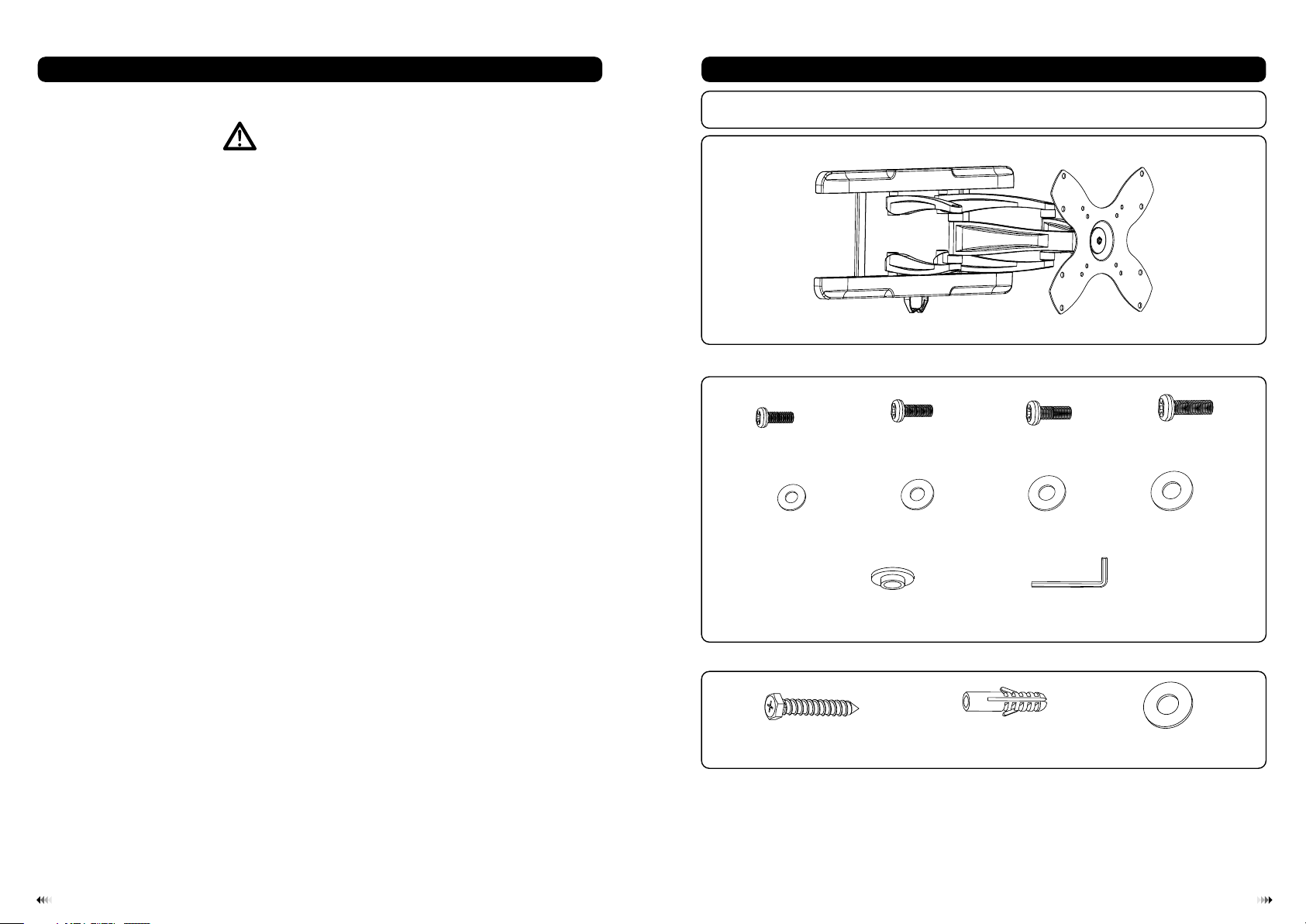
Package M
• Never exceed the maximum load capacity.
• If mounting to wood wall studs, make sure that mounting screws are anchored into
the center of the studs. Use of an “edge to edge” stud finder is highly recommended.
• Always use an assistant or mechanical lifting equipment to safely lift and position
equipment.
• Tighten screws firmly, but do not over tighten. Over tightening can damage the items,
greatly reducing their holding power.
• This product intended for indoor use only. Using this product outdoors could lead to
product failure and personal injury.
M4x14 ( x4 )
M-A
D4 wash er ( x4)
Package W
ST6.3 x5 5 (x6)
M-E
W-A
M5x14 ( x4 )
M-B
D5 wash er ( x4)
M-F
ø13.5 xø 5.5x3 .2 (x4)
M-I
concr et e ancho r (x6)
M6x14 ( x4 )
D6 wash er ( x4)
allen key 4mm (x1)
W-B
M-C
M-G
Tools required
Phillips Head Screw driver(200mm length exclude the handle)
·
M6 Socket and Wrench
·
·
Electric drill and 10mm masonry bit for concrete wall installation
·
Marking Pen
·
Hammer
M-J
M8x14 ( x4 )
M-D
D8 wash er ( x4)
M-H
washe r( ø6.5x ø24) (x 6)
W-C
21
Page 3

Disassemble the wa ll mount as shown below.
Loosen the safety sc rews with a proper screwdriver to di sassemble the adapter bracket fo r easy
installation.
Woo d Stud Wall Mounting:
1a
WARNING
• Make sure that the supporting surface will safely support the combined load of the
equipment and all attached hardware and components.
W-A
Solid Bri ck And Concrete Block Mounting:
1b
W-C
Make su re t he wall p late is
corre ct ly plac ed
WARNING
•
When installing to a cinder block wall, please verify you have a minimum of
concrete thickness. Do not drill directly into mortar joints, be sure to mount to a
solid part of the block generally 1” minimum from the side of the block. It is
suggested to use an electric drill with a slow setting instead of a hammer to avoid
breaking the wall.
•
Please verify the supporting surface will safely support the capacity of hardware
and equipment prior to installing.
fig. 1.1
• Tighten wood screws firmly, but do not over tighten. Over tightening can damage
the screws, greatly reducing their holding power.
• Make sure that mounting screws are anchored into the center of the studs. Use of
an “edge to edge” stud finder is highly recommended.
• Hardware provided is for attachment of mount through standard thickness drywall
or plaster into studs. Installers are responsible to provide hardware for other types
of mounting situations.
• Use a st ud finder to locate th e edges of the stud s. Use of an edge-to-e dge stud finde r is highly r ecommended.
Based on th eir edges , draw a vert ical line down each st ud’s cent er.
• Place wal l plate on wa ll as a template. An d mark the center of the fo ur mounting ho les . Make sure that
the mount ing holes are on the stu d centerline .
• Drill fou r 1/8” (3mm ) dia. Hole s 1.2” (30m m) deep. Ma ke sure tha t the wall pl ate is leve l, secure it using
four scre ws (W- A) as shown in fig. 1.1.
• Use the wall p lat e to ma rk six holes l oca tions on the wall . as sh own in fig.1 .2.
• Pre-drill the se ho les with a 10m m mas onry bit to at leas t 60m m in depth. In ser t a con crete anch or (W -B)
into each of thes e hol es. Attach the wal l pla te to the wall u sin g six s crews (W-A) and six wa she rs (W-C) ,
as shown in fig.1 .3.
fig. 1.2
43
Page 4

W-B
W-C
W-A
Make su re t he wall p late is
corre ct ly plac ed
fig. 1.3
Top of disp la y
Mounting The Plastic Covers and The Cable Clip
2
• Snap the plastic cov ers to top and bottom of wall pla te rails and then insert the cable cli p from the bottom of the
plastic cover as sho wn in fig. 2.1.
fig. 2.1
Installing Adapte r Brack et:
3
• To prevent s cra tching the scre en, s et a cl oth o n a fla t, le vel s urface tha t wil l sup por t the weight of the
scr een.
• Pla ce sc reen face side do wn. P lac e adapter on the back of scre en, a lig n to ho les, and center o n bac k of
scr een, as shown in fig.3 .1.
• Att ach the adapter brac ket t o the b ack o f the s creen using the appr opr iate combi nat ion of screws,
was hers, and space rs, a s sho wn in f ig.3.2 and fig. 3.3 .
fig.3.1
• Beg in with the prope r scr ew, ha nd th rea d through washe r and a dap ter bracke t int o scr een a s sho wn in fig.3.2
and f ig. 3.3.
• Scr ew mu st make at least three f ull t urn s int o mounting h ole a nd fi t snu g int o place. Do not over tighte n.
• Rep eat for remaini ng mo unt ing holes, l eve l bra cket and tighte n scr ews .
M-G/M -H
M-C/M -D
fig. 3.2
Installing the Display
4
Hang the bracket mou nted display onto the plate o f articulated arm assembly, and then tighten safety screws
securely with a prop er screwdriver as shown in fi g.4.1.
Important: Make su re the bracket mounted display is co rrectly mounted and the saf ety screws are tightened
securely before lo osening the display.
You can adjust tighter or looser u sing a 4mm allen key according to the we ight of the display you will be installing.
M-I
M-A/M -B
M-E/M -F
fig. 3.3
65
 Loading...