

Page 1
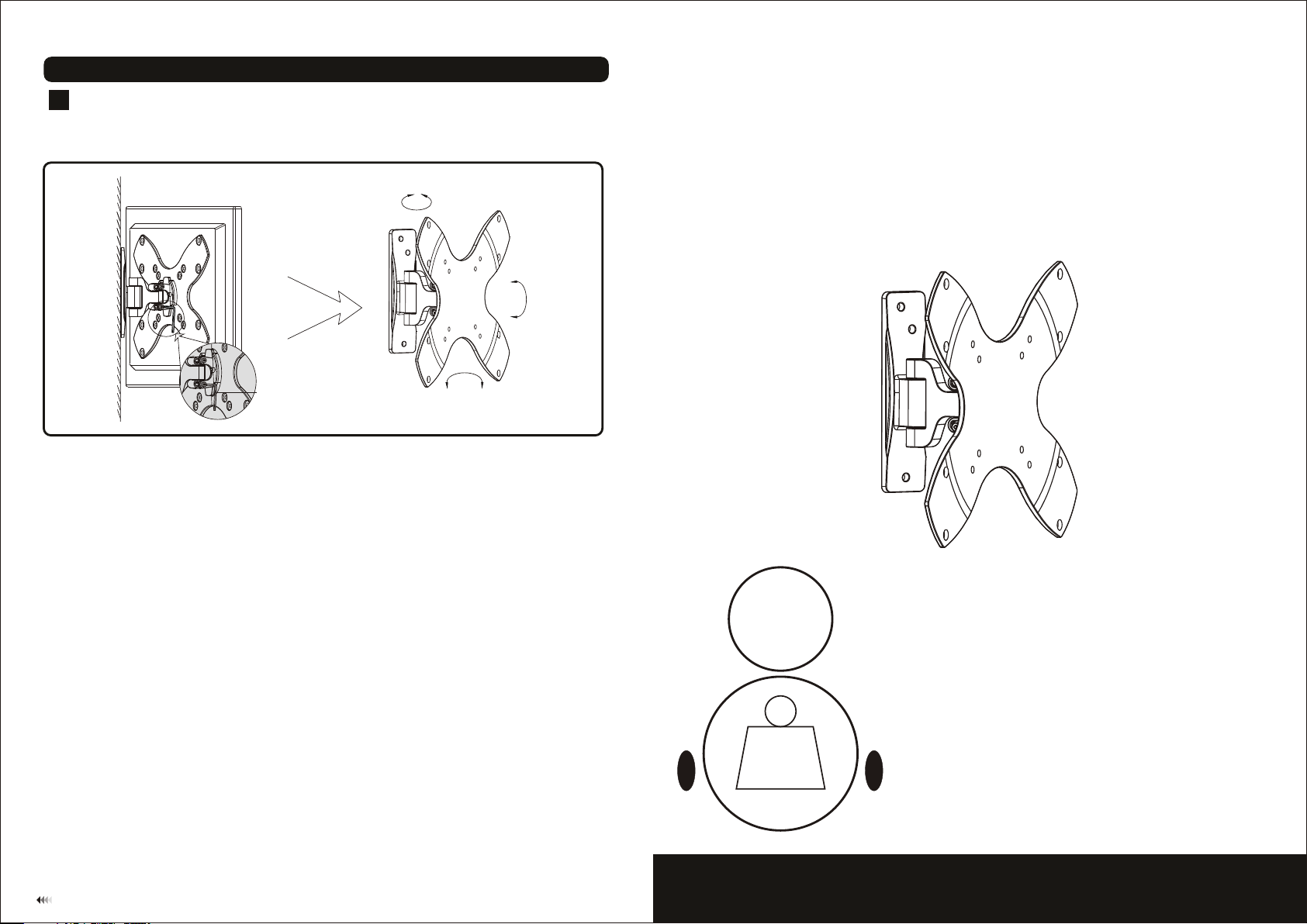
Pitching angle adjustment
4
• Tighten the screws till the di splay angle can be fixed, then push or p ull from top or bottom of screen to adju st
the display to the des ired angle.
• The pitching angle can be adjusted between -20° ~ + 20°, swivel: ±45°, pivot: ±10°, as sho wn in fig.4.1.
±4 5°
+2 0°
-20°
INSTALLATION INSTRUCTIONS
M-J
Maintenance
Once you ha ve mounte d the brack et and the fl at screen , check tha t they are su ffic iently se cure and sa fe to use.
You should check whether screws are fixed well each two months. If you hav e any doubt s regardi ng the
install ation, pl ease cons ult our ret ailer or se rvice dep artment f or detail .
+1 0°-10°
fig. 4.1
Pitchin g an gle:
-20° ~ +20°
Swivel: ±45°
20kg
(44lbs)
MAX
LCD Wall Mount
Model: MDA03-220
7
Max Loa d Cap aci ty : 20k g(4 4lbs)
Page 2
NOTE: Read entire instruction sheet before you start installation and assembly.
WARNING
• Do not begin the installation of the product before you have read and understood the
instructions and warnings contained in this installation sheet. If you have any question
regarding any of the instruction or warning, Please contact your local distributor.
• Please refer to installation guide recommendation for required distance from wall to
avoid risk of property damage.
• This product should only be installed by someone of good mechanical aptitude, with
experience and basic building, and fully understands.
• Make sure that the supporting surface will safely support the combined load of the
equipment and all attached hardware and components.
• Never exceed the maximum load capacity.
• If mounting to wood wall studs, make sure that mounting screws are anchored into
the center of the studs. Use of an “edge to edge” stud finder is highly recommended.
• Always use an assistant or mechanical lifting equipment to safely lift and position
equipment.
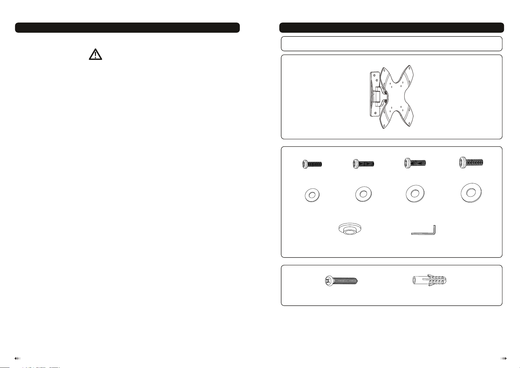
Component Checklist
IMPORTANT: Ens ure y ou h ave r ece ived al l par ts agai nst t he comp one nt chec kli st prio r to in sta ll ing . If an y pa rts
are m is sin g or fa ul ty, te lep hon e the spe cia l franc his er for a re pla cemen t.
Package M
M4x14
(x4) M5x14 ( x4 )
M-A
ø ø10
D4 ( 4.5x )
washe r
M-E
(x4)
M-B
D (ø .5xø )
5 5 12
(x4)
washe r
M-F
M6x14 ( x4 )
M-C
D6 (ø6. 3x ø )
washe r
M-G
(x4)
16
M8x15 ( x4 )
M-D
D8 (ø8. 3x ø )
washe r
M-H
(x4)
16
• Tighten screws firmly, but do not over tighten. Over tightening can damage the items,
greatly reducing their holding power.
• This products intended for indoor use only. Using this product outdoors could lead to
product failure and personal injury.
ø13.5 xø 5.5x3 .2 (x4)
M-I
3mm allen key (x1)
Package W
ST 5. 5x 50 (x3)
lag bol t concr et e ancho r
W-A
Tools required
·
Phillips Head Screw driver(200mm length exclude the handle)
·
Electric drill and 8mm masonry bit for concrete wall installation
·
Marking Pen
·
Hammer
M-J
W-B
(x3)
21
Page 3

Dis assemble the adapter bracket fro m the ass emble pr odu ct to eas y for installation, Loosen the safety
scr ews by using 3mm all en key(M-J) and take the adapte r bracket off art iculated ar m assemb le. as s hown
below.
WOOD ST UD WALL MOUNTING:
1a
Stud
SOLID B RICK AND CONCRETE B LOCK MO UNTING:
1b
W-A
fig. 1.1
WARNING
• Make sure that the supporting surface will safely support the combined load of the
equipment and all attached hardware and components.
• Tighten wood screws firmly, but do not over tighten. Over tightening can damage
the screws, greatly reducing their holding power.
• Make sure that mounting screws are anchored into the center of the studs. Use of
an “edge to edge” stud finder is highly recommended.
• Hardware provided is for attachment of mount through standard thickness drywall
or plaster into studs. Installers are responsible to provide hardware for other types
of mounting situations.
• Use a st ud finder to locate th e edges of the stud s. Use of an edge-to-e dge stud finde r is highly
recommended. Ba sed on thei r edges, dr aw a ver tic al line dow n each stud ’s cen ter.
• Place wal l plate on wa ll as a template. And mar k the cente r of the thre e mounting hol es. Make su re that
the mount ing holes are on the stu d centerline .
• Drill thr ee 1/8” (3m m) dia. Hol es 1.2” (30 mm) deep. Make sure th at the wall p late is lev el, secure it using
three woo d screws (W-A) as show n in fig . 1.1.
WARNING
• When installing wall mounts on cinder block, verify that you have a minimum of
1-3/8” of actual concrete thickness in the hole to be used for the concrete anchors.
Do not drill into mortar joints! Be sure to mount in a solid part of the block,
generally 1” minimum from the side of the block. It is suggested electric drill on
slow setting is used to drill the hole instead of a hammer drill to avoid breaking out
the back of the hole when entering a void or cavity.
• Installer must verify that the supporting surface will safely support the combined
load of the equipment and all attached hardware and components.
• Use the wall plat e as a te mplate to ma rk 3 ho les locations o n the w all, as show n in fi g.1 .2.
• Pre-drill the se ho les with a 8mm m aso nry bit to at least 5 0mm i n depth. Ins ert a c onc rete ancho r (W- B)
into each of thes e hol es. Attach the wal l pla te to the wall u sin g 3 woo d screws (W-A) as show n in fi g.1.3.
43
Page 4

W-A
W-B
M-G
M-H
M-I
M-E
M-F
fig. 1.2
Installing Adapter Bracket
2
• To prevent scratching the screen, set a cloth on a flat, level surface that will support the weight of the screen.
• Place screen face side down. Place dapter racket on the back of screen, align to holes, as shown in fig.2
• Attach the adapter bracket to the back of the screen using appropriate combination of washers and screws. as
shown in fig.2.2
the a b .1
fig. 1.3
M-C
M-D
For VESA 75x75 / 100x100 / 200x100 / 200x200mm compliant
Installing the Display
3
• Place the adapter br acket mounted display ont o the plate of articulated arm assem bly, as shown in fig 3.1.
• Adjust the display level, and then tighten the safe ty screws with 3mm allen key(M-J). D o not over tighten!
as shown in fig 3.1.
Important: Make su re the brackets mounted display is c orrectly mounted and the sa fety locking screws are
locked safely befo re loosening the display.
M-A
M-B
fig. 2.2
fig. 2.1
M-J
fig. 3.1
65
 Loading...