

Page 1
INSTALLATION INSTRUCTIONS
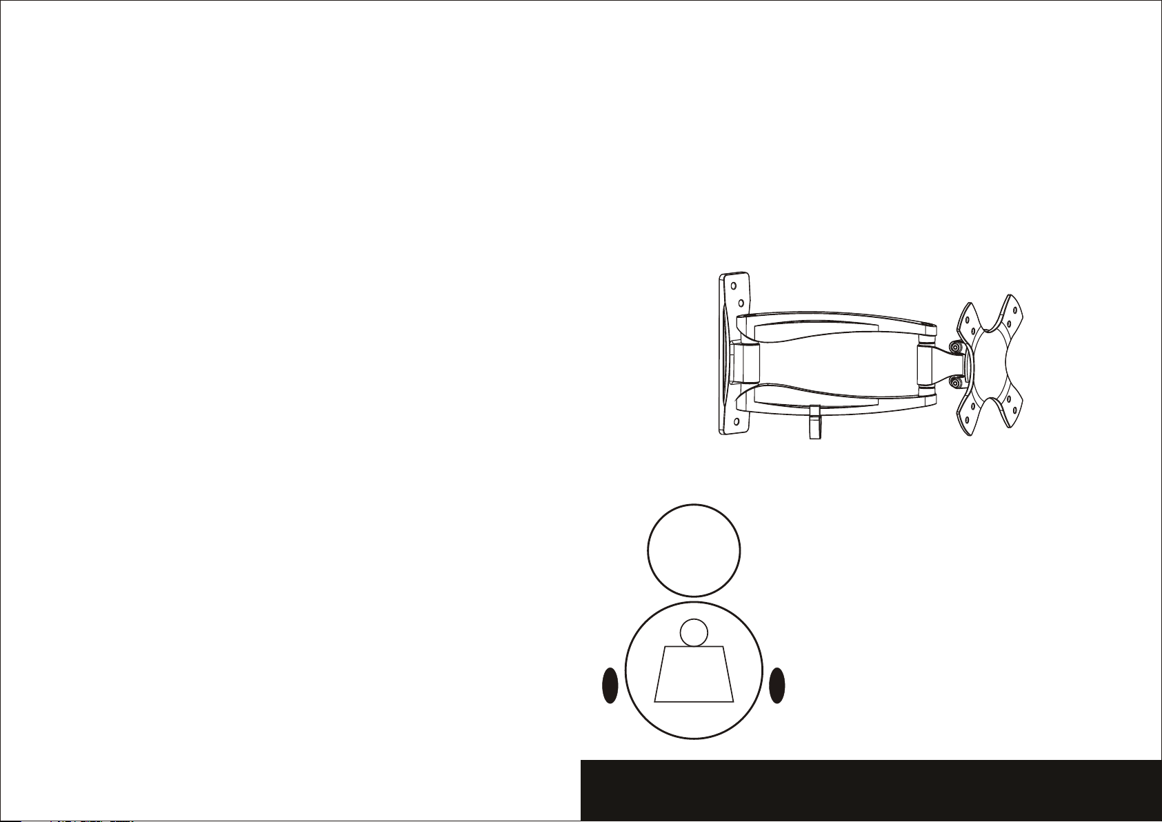
Pitch in g angle :
-20° ~ +20°
Swive l: ±90°
15kg
(33lbs)
MAX
LCD Wall Mount
Model: MDA03-112
Max Load Cap aci ty: 1 5kg (33 lbs )
Page 2
NOTE: Read enti re i ns truction shee t be fo re you start inst al la tion and assemb ly.
WARNING
• Do not begin the installation of the product before you have read and understood the
instructions and warnings contained in this installation sheet. If you have any question
regarding any of the instruction or warning, Please contact your local distributor.
• Please refer to installation guide recommendation for required distance from wall to
avoid risk of property damage.
• This product should only be installed by someone of good mechanical aptitude, with
experience and basic building, and fully understands.
• Make sure that the supporting surface will safely support the combined load of the
equipment and all attached hardware and components.
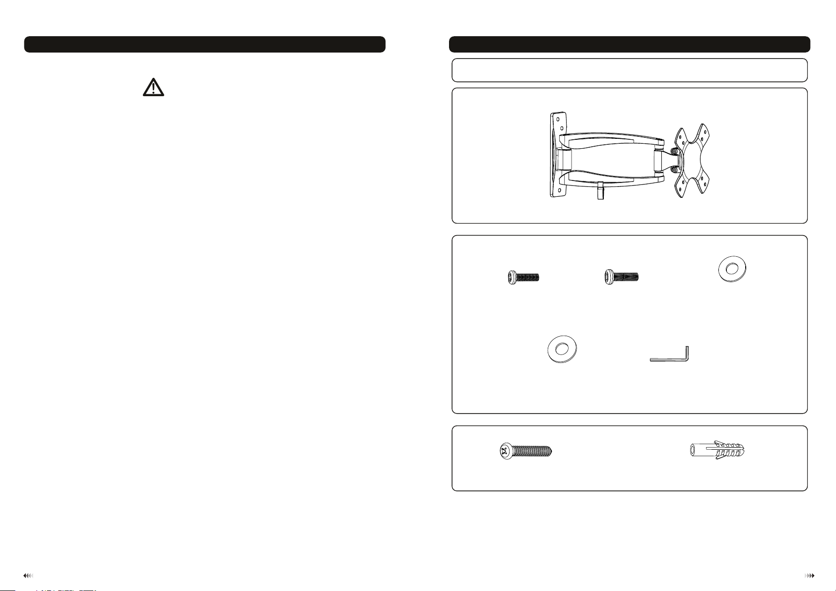
Component Che ck li st
IMPORTAN T: Ensure you ha ve re cei ved a ll pa rts agains t the c omp one nt ch eck list pr ior t o ins tal lin g. If a ny parts
are m issin g or fa ult y, tel eph one t he sp eci al fr anchi ser f or a re pla cem ent .
Package M
• Never exceed the maximum load capacity.
• If mounting to wood wall studs, make sure that mounting screws are anchored into
the center of the studs. Use of an “edge to edge” stud finder is highly recommended.
• Always use an assistant or mechanical lifting equipment to safely lift and position
equipment.
• Tighten screws firmly, but do not over tighten. Over tightening can damage the items,
greatly reducing their holding power.
• This products intended for indoor use only. Using this product outdoors could lead to
product failure and personal injury.
M4x14
(x4) M5x14 ( x4)
M-A
5 5 12
D (ø .5xø )
washe r
(x4)
M-D
M-B
3mm allen key (x1)
M-E
Package W
ST 5. 5x50 (x3)
lag bol t concr ete anc hor
W-A
Tools required
·
Phillips Head Screw driver(200mm length exclude the handle)
·
Electric drill and 8mm masonry bit for concrete wall installation
·
Marking Pen
·
Hammer
D4 ( 4.5x )
ø ø10
washe r
(x4)
M-C
(x3)
W-B
21
Page 3

Dis assembl e the adapt er brac ket from the ass emble pr oduct to eas y for ins tallati on, Loo sen the saf ety
scr ews by using 3mm allen ke y(M-E) a nd take the ad apter br acket off art iculate d arm ass emble. a s sho wn
below.
WOOD STUD WAL L MOU NTING :
1a
Stud
SOLID BRICK AND CONCRETE BL OCK MOUNTING:
1b
W-A
fig. 1.1
WARNING
• Make sure that the supporting surface will safely support the combined load of the
equipment and all attached hardware and components.
• Tighten wood screws firmly, but do not over tighten. Over tightening can damage
the screws, greatly reducing their holding power.
• Make sure that mounting screws are anchored into the center of the studs. Use of
an “edge to edge” stud finder is highly recommended.
• Hardware provided is for attachment of mount through standard thickness drywall
or plaster into studs. Installers are responsible to provide hardware for other types
of mounting situations.
• Use a st ud fin der to loca te the e dges of the st uds. Use of an edge-to-edg e stud f inder is highly
recommende d. Bas ed on th eir edges , draw a vertical line do wn each stud’s center.
• Place wal l plat e on wal l as a tem plate. And ma rk the center of the thre e mountin g hole s. Make sure that
the mount ing holes are on the stud cente rline.
• Drill thr ee 1/8 ” (3mm) dia. Hole s 1.2” (30mm) dee p. Mak e sure that the wal l plat e is lev el, secur e it usi ng
three woo d screws (W- A) as sh own in fig. 1.1.
WARNING
• When installing wall mounts on cinder block, verify that you have a minimum of
1-3/8” of actual concrete thickness in the hole to be used for the concrete anchors.
Do not drill into mortar joints! Be sure to mount in a solid part of the block,
generally 1” minimum from the side of the block. It is suggested electric drill on
slow setting is used to drill the hole instead of a hammer drill to avoid breaking out
the back of the hole when entering a void or cavity.
• Installer must verify that the supporting surface will safely support the combined
load of the equipment and all attached hardware and components.
• Use the wall plate as a template to mark 3 holes locations on the wall, as show n in fi g.1 .2.
• Pre-drill these holes with a 8mm masonry bit to at least 50mm in depth. Ins ert a C onc ret e Anchor (W-B)
into each of these holes. Attach the wall plate to the wall using 3 wood screws (W-A ) as shown in fig.1.3.
43
Page 4

W-A
M-A
M-B
M-C
M-D
W-B
fig. 1.2
Installing Adapter Bracket
2
• To prevent scratching the screen, set a cloth on a flat, level surface that will support the weight of the screen.
• Place screen face side down. Place dapter racket on the back of screen, align to holes, as shown in fig.2
• Attach the adapter bracket to the back of the screen using appropriate combination of washers and screws. as
shown in fig.2.2
Installing the Display
3
• Place the adapter bracket mounted displa y onto th e plate of articulated arm assembly, as shown in fig 3.1.
• Adjust the display level, and then tighten the s afety s crews with 3mm allen key(M-E). Do not over tighten!
as shown in fig 3.1.
Important: Make sure the brackets mounte d displ ay is correctly mounted and the safety locking screw s are
locked safely before loosening the display.
the a b .1
For V ESA 75x75 / 100x100 mm compliant
fig. 1.3
fig. 2.2fig. 2.1
M-E
fig. 3.1
Pitching angle adjustment
4
• Tighten the screws til l the dis play angle can be fixed, then push or pull from top or bottom of scre en to adjust
the display to the desired angle.
• The pitching angle can be adjusted between -20° ~ +20 °, swivel: ±90°, pivot: ±10°, as shown in fig.4.1.
±9 0°
+2 0°
-20°
±9 0°
M-E
Maintenance
Once you ha ve mounted the bracke t and the flat screen, ch eck that they are sufficiently se cure and safe to use.
You should check wh ethe r screws are fixe d well e ach two months. I f you ha ve any doubts reg ardi ng the
install ation, please consu lt our retailer or serv ice department for de tail.
+1 0°-10°
fig. 4.1
65
 Loading...