

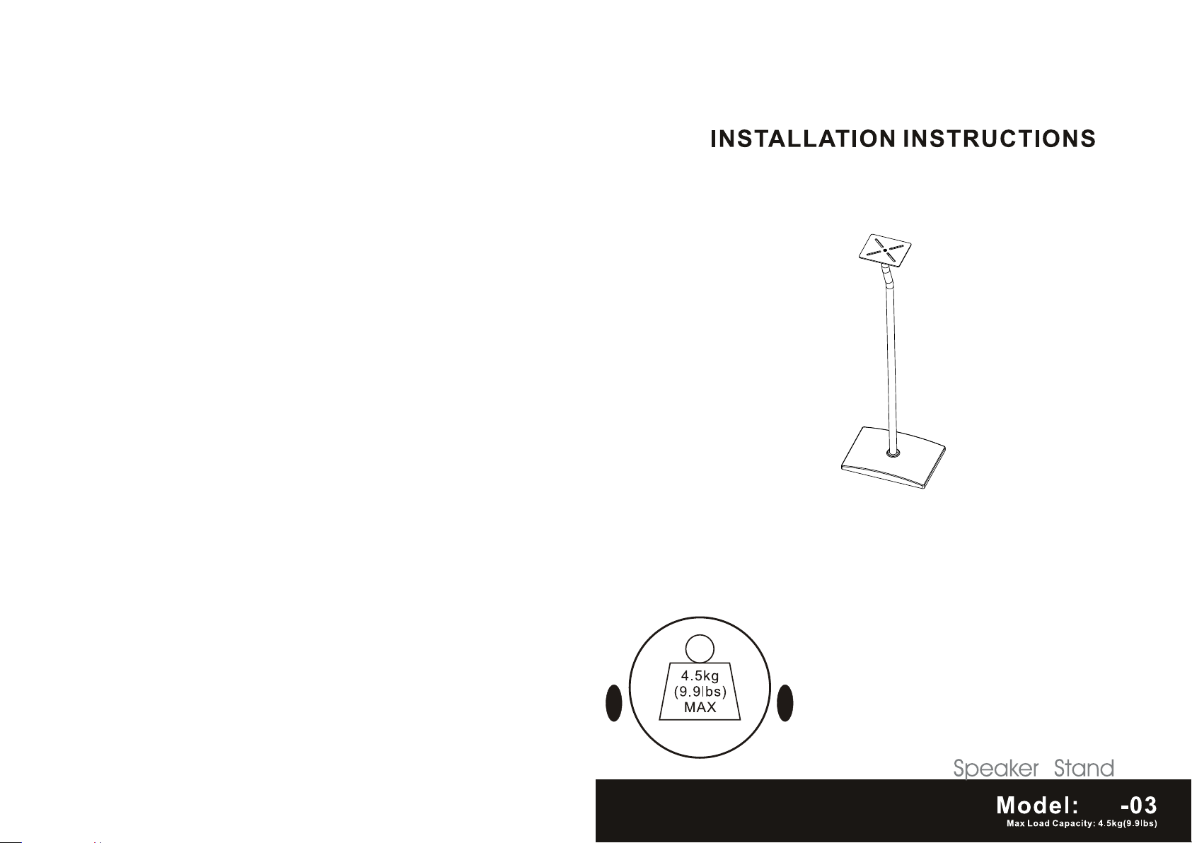
Page 1
MS
Page 2
NOTE: Read entire instruction sheet before you start installtion and assembly.
WARNING
• Do not begin to installation of the product on you have read and understand the
instructions and warnings contained in this Installation Sheet. If you have any question
regarding any of the instruction or warning, Please contact your local distributor.
• Make sure that the supporting surface will safely support the combined load of the
equipment and all attached hardware and components.
• Never exceed the Maximum Load Capacity.
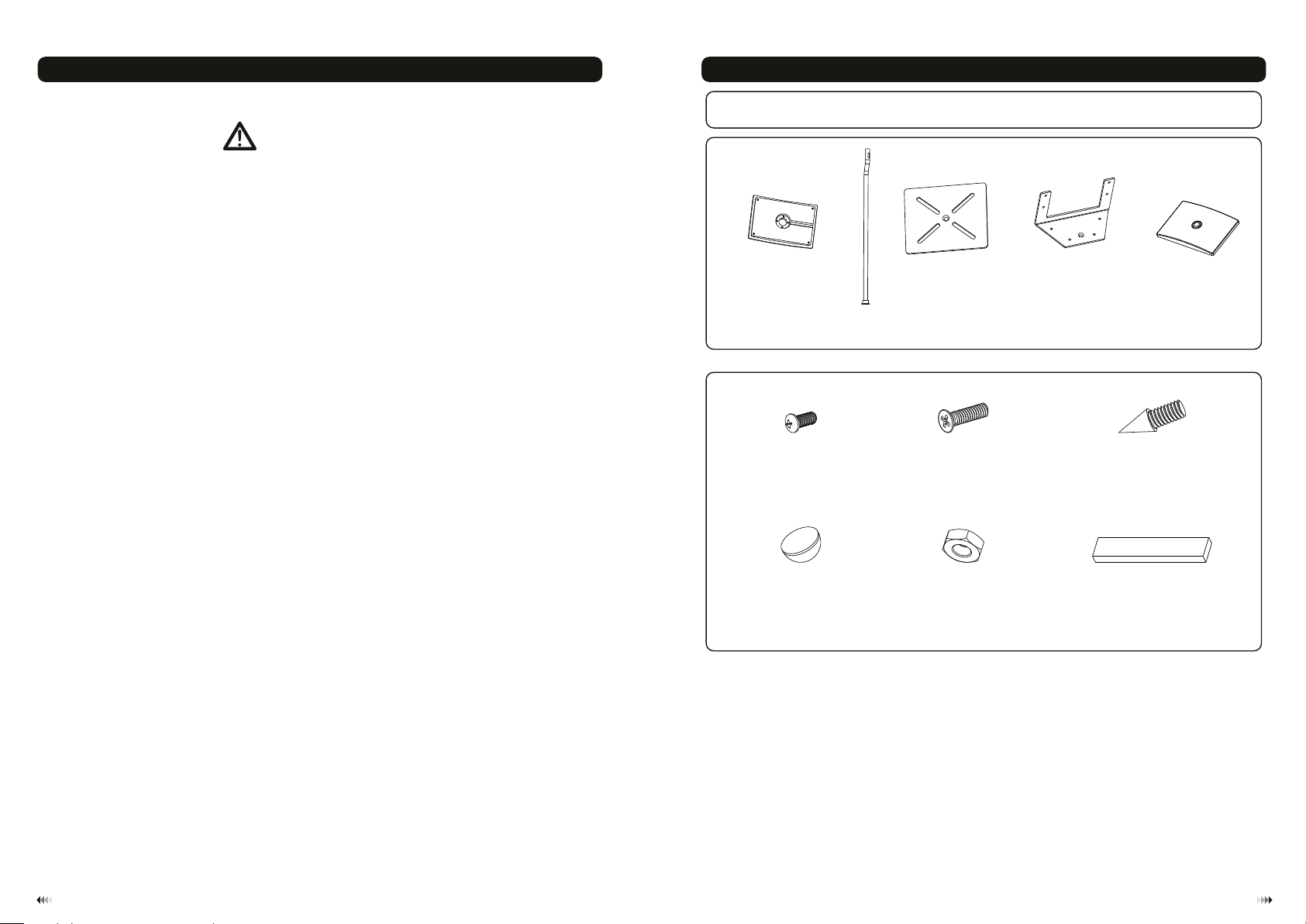
Component Checklist
IMPORTANT: Ens ure y ou h ave r ece iv ed al l par ts a gai nst t he c omp one nt c hec kli st p rio r to in st all ing . If a ny pa rts
are m is sin g or fa ul ty, te lep hon e th e spe cia l fr anc his er f or a pl ace me nt.
Speak er S tand Ba se A(x1)
Pilla r
Mount in g P a 1
(x1)
B
l te (x1) Mount in g 2
C
Plate (x 1) Plast ic C over E(x1)
D
• Always use an assistant or mechanical lifting equipment to safely lift and position
equipment.
• Tighten screws firmly, but do not over tighten. Over tightening can damage the items,
greatly reducing their holding power.
• This products intended for indoor use only. Use of this product outdoors could lead to
product failure and personal injury.
Package M
M5x16
(x4) Steel I so latio n Spike ( x4 )
M-A
Rubbe r Fo otpad ( x4)
M-D
(x1)M5x12
M-B
M6 Nut (x 4)
M-E
Tools required
Phillips Head Screw driver(200mm length exclude the handle)
·
M6 Socket and Wrench
·
M-C
Self Adh es ive Pad ( x4)
M-F
1
2
Page 3

Attachment of footpad to metal base
1
1a. For hard floor pla cement
Place speak er stand base(A) upside down on grou nd and paste rubber footpad o n the 4 holes, as shown in fig.1. 1
M-D
A
Attachment of speaker stand base to pillar
2
•Insert pillar (B) from the bottom of speaker stand base and turn pillar to align to mount ing hole, Secure them with
M5x12(M-A)screw. Then tighten the screw ,but do not over tighten.
•Turn the base over ( isolation spikes can scratch floors, use caution) Please ensure cable out let on top of pole is
in line with channel in base.as shown in fig.2.1.
M-A
fig.1.1
1b. For carpet place ment
Place speak er stand base(A) upside down on grou nd and thread steel isolati on spikes (M-C) through M6 nu t
(M-E)in the 4 holes.Adjust the height of speake r stand base by screwing the nu t as request . as shown in fig.1.2.
M-C
M-E
A
fig.1.2
B
Mounting plastic cover
3
Cover the spe aker stand with the plastic cover (E ) through pillar. as shown in fig .3.1
B
E
fig.2.1
fig.3.1
43
Page 4

Mounting plate
4
Attach mounting plate to the top of pillar with the a ppropriate combinatio n of screw(M-B). Make sure mountin g
plate is leve l. Then tighten the scr ew ,but do not over tighten. as shown in f ig. 4.1 and fig.4.2.
M-B
C
Mounting speaker
5
Remove the ba cking paper so the adhesive is expos ed. Then place the adhesive pad on the mounting plat e.
Peel the othe r side of the backing paper on the mount ing Self adhesive pad . Then place the speaker on the
center of the mounting plate. as shown in fig.5.1 a nd fig.5.2.
M-F
fig.4.1
fig.5.1
M-F
M-B
D
fig.4.2
Maintenance
Once you have mounted the stand and th e spea ker, check that they are sufficient ly sec ure an d safe to use.
You shou ld che ck whe ther screws are fi xed we ll eac h two months. If you have any doubts regardi ng the
installation, please consult our retailer or service depart ment for det ail.
fig.5.2
65
 Loading...