

Page 1
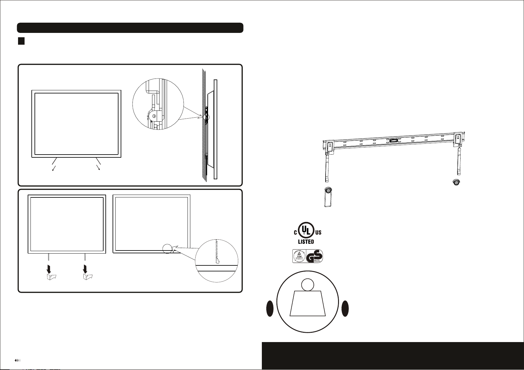
Locking Adapter Brackets
4
• First, pull the outside safety straps on the adapter brackets, and then slowly
allow display to return to the wall. Finally loosen the safety straps and lock the
adapter brackets.
INSTALLATION INSTRUCTIONS
fig. 4.1
The saf et y strap s can be fo ld ed and
keep in b ac k of the di splay.
fig. 4.2
Important: Make sure the TV is correctly hooked and the safety locking bars are locked safely.
Maintenance
• Once you have mounted the bracket and the flat screen, check that they are
sufficiently secure and safe to use,
• You should regularly check that the screws and hardware are secure to your wall every
two months for safety.
• If you have any doubts regarding the installation, please consult our retailer or service
department for further details.
7
50kg
(110lbs)
MAX
LED WALL MOUNT
Model: MED-028
Max Loa d Cap aci ty : 50k g(11 0lbs)
Page 2
NOTE: Read entire instruction sheet before you start installtion and assembly.
WARNING
• Do not begin the installation of the product, until you have read and understood the
instructions and warnings provided in the installation manual. If you have any
questions regarding the warnings and instructions, please contact your local supplier.
• Please refer to the manufacturers installation guide for proper wall recommendation
distance to avoid the risk of property damage.
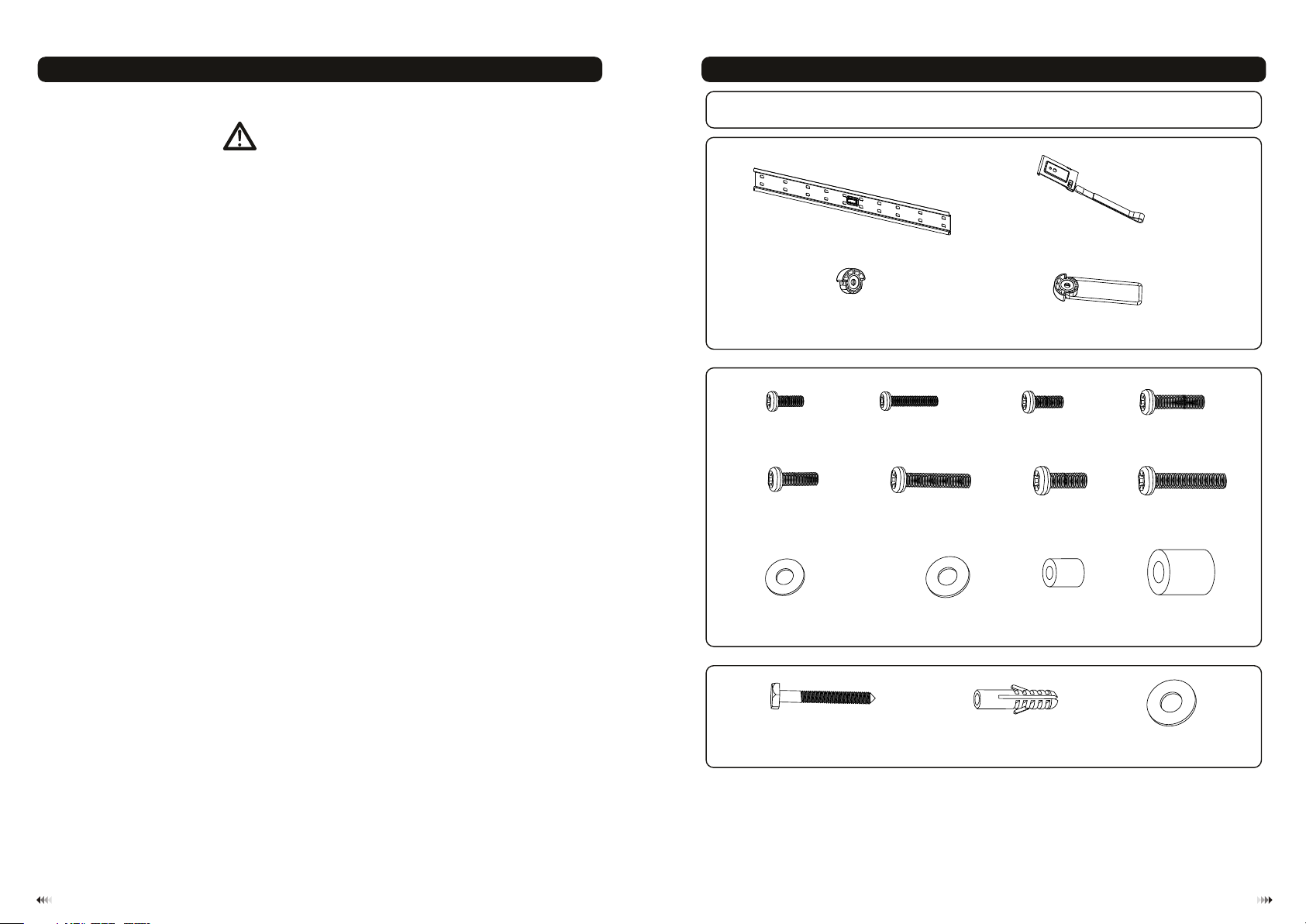
Component Checklist
IMPORTANT: Ple ase e ns ure a ll pa rts lis ted a re incl ude d prior t o you r insta lla tion. I f any p art s ar e mis sin g or
fau lt y, ple ase c ont act the s pec ial fra nch iser fo r a rep lacem ent .
wall pl at e
A
(x1)
(x2)Adapt er b racke t
B
• This product should only be installed by someone of good mechanical aptitude, with
experience and basic building, and fully understands.
• Make sure that the supporting surface will safely support the combined load of the
equipment and all attached hardware and components.
• Never exceed the Maximum Load Capacity.
• If mounting to wood wall studs, make sure that mounting screws are anchored into
the center of the studs. Use of an “edge to edge” stud finder is highly recommended.
• Always use an assistant or mechanical lifting equipment to safely lift and position
equipment.
• Tighten screws firmly, but do not over tighten. Over tightening can damage the items,
greatly reducing their holding power.
• This product is intended for indoor use only. The use of this product other then indoors
could lead to product failure and personal injury,
Suppo rt ing spa cer (x1 )
Package M
M4x14
(x4)
M-A
M6x14 ( x4 )
M-E
Ø Ø (x )12x 5.5 Washe r 2
M-I
Package W
M6x55 (x )
lag bol t 6
W-A
C
M4x30
(x4)
M-B
M6x30 ( x4 )
M-F
Ø Ø (x2)16x 8.2 Washe r
M-J
concr et e ancho r 6
Suppo rt ing spa cer (x1 )
M5x14 ( x4 )
M-C
M8x14 ( x4 )
Ø ( 4)12xØ6 x1 3 x
W-B
D
M-G
M-K
(x )
M5x30 ( x4 )
M-D
(x4)
M8x30
M-H
Ø17.5 xØ 8x20
Ø Ø (x )16x 6.2 Washe r 6
M-L
W-C
(x4)
Tools required
Phillips Head Screw driver(200mm length exclude the handle)
·
M6 Socket and Wrench
·
·
Electric drill and 10mm masonry bit for concrete wall installation
·
Marking Pen
·
Hammer
21
Page 3

WOOD ST UD WALL MOUNTING:
1a
WARNING
• Make sure that the supporting surface will safely support the combined load of the equipment
and all attached hardware and components.
• Tighten wood screws firmly, but do not overtighten. Overtightening can damage the screws,
greatly reducing their holding power.
• Make sure that mounting screws are anchored into the center of the studs. Use of an “edge to
edge” stud finder is highly recommended.
• Hardware provided is for attachment of mount through standard thickness drywall or plaster
into studs. Installers are responsible to provide hardware for other types of mounting situations.
•
Wall plate ca n be mount ed to t wo st uds. Use a stud finder to locate t he ed ges o f the s tud s. Use of an
edg e-to-edg e stu d fin der is highly recomm end ed. Based on thei r edg es, d raw a vert ical line down ea ch
stu d’s c ent er.
•
Place wall plat e on wall as a temp lat e. And m ark t he ce nter of the four mount ing h ole s. Ma ke sure that the
mou nting hole s are on the stud c ent erline.
• and four M6 washers
Drill four 1/8” (3mm ) dia . Hol es 1. 2” (30mm) deep, s ecu re it u sin g four lag bolts (W-A)
(W- C)
as sh own in fig . 1.1.
3mm
Stud
W-C
W-A
• Use t he Wall Plate as a template to mark 6 hole s loc ations on the wall. Four in the to p row slot s and t wo
more in th e bottom row, as shown in fig. 1.2 .
• Pre -drill these ho les w ith a 1 0mm m asonry bit to at least 60mm in dep th. I nse rt a Co ncrete Anchor (W-B)
into each of these holes. Attac h the Wa ll Pl ate to the wall using 6 Lag Bol ts (W-A) and 6 M6 Washe rs (W-C) ,
as in f ig.1.3.
W-C
W-A
fig. 1.2 fig. 1.3
Installing Adapte r Brack ets
2
To prev ent s cra tching the scre en, s et a cl oth on a fla t, le vel surfac e tha t wil l sup port the weight of the
•
screen.
Place screen fa ce si de do wn. P lace adapter br ack et an d supporti ng sp ace r on th e bac k of sc reen, alig n
•
to ho les , as sh own in fig.2.1.
Attach the adap ter b rac kets to th e bac k of th e screen using th e app rop riate
• and supportin g spa cer
com bination o f scr ews , was hers, and space rs, a s sho wn in fig.2.2, fig.2 .3, f ig.2.4 fig.2.5.
W-B
and
SOLID B RICK AND CONCRETE B LOCK MO UNTING:
1b
WARNING
• When installing wall mounts on cinder block, verify that you have a minimum of 1-3/8” of actual
concrete thickness in the hole to be used for the concrete anchors. Do not drill into mortar
joints! Be sure to mount in a solid part of the block, generally 1” minimum from the side of the
block. It is suggested electric drill on slow setting is used to drill the hole instead of a hammer
drill to avoid breaking out the back of the hole when entering a void or cavity.
• Installer must verify that the supporting surface will safely support the combined load of the
equipment an d all attached hardware and components.
3
fig. 1.1
fig. 2.1
NOTE: For fl at ba ck screens procee d to st ep 2-1. For bump- out or reces sed back scr een skip to
step 2-2.
4
Page 4

For Flat Back Screen
2
•
Begin with the shortest length scr ew, hand thre ad through washer and adapter bracket into screen as shown
below.
1
•
Screw must make at least three full turns into mounting hol e and fit snug into place. Do not over tighten.
•
If screw cannot make three full turns into screen, selec t a longer len gth screw from the baff led fastener pack.
Repeat for remaining mounting holes, level brackets and tighten screws.
NOTE: Spacer may not be used, depending upon the type of screen.
M-A
M-C
M-A
M-C
M-I
fig. 2.2 fig. 2.3
For Bump-out or Recessed Back Screen
2
Begin with longer length screw, hand thread through washer, into screen as
shown below. Screw must make at least three full turns into mounting hole and fit snug into place. Do not over
tighten. If screw cannot make three full turns into screen, select a longer length screw from the baffled fastener
2
pack. Repeat for remaining mounting holes and tighten screws.
M-K
M-K
M-B
M-D
M-B
M-D
the supporting spacers and sliders
M-L
M-L
M-E
M-G
M-E
M-G
M-F
M-H
M-F
M-H
M-J
Cable Managem ent
3
• Slo wly pull bottom of display awa y fro m wal l unt il ki cks tand of the supporti ng sp ace r(D) fully reaches its
dow n pos ition.
•Attach or adjust cable s as neces sar y on ba ck of d isp lay.
2
•To dis eng age k ickstand, sli ght ly pu ll di splay away from wall. Slowly a llo w dis play to re turn to th e wall.
fig. 3.1
M-I
fig. 2.4 fig. 2.5
Hang the brackets mounted TV onto the wall plate
Warning: A mini mum o f two q ual ified people are requir ed fo r thi s ope rat ion.
3
After the wall mount has been safel y sec ure d to th e wal l, wi th 2 pe opl e car efully lift your TV and h ook the
•
top hooks over the top of the wa ll pl ate rail. , see Fig. 3.1.
1
M-J
fig. 3.2
65
 Loading...