

Page 1
Instruction Manual for
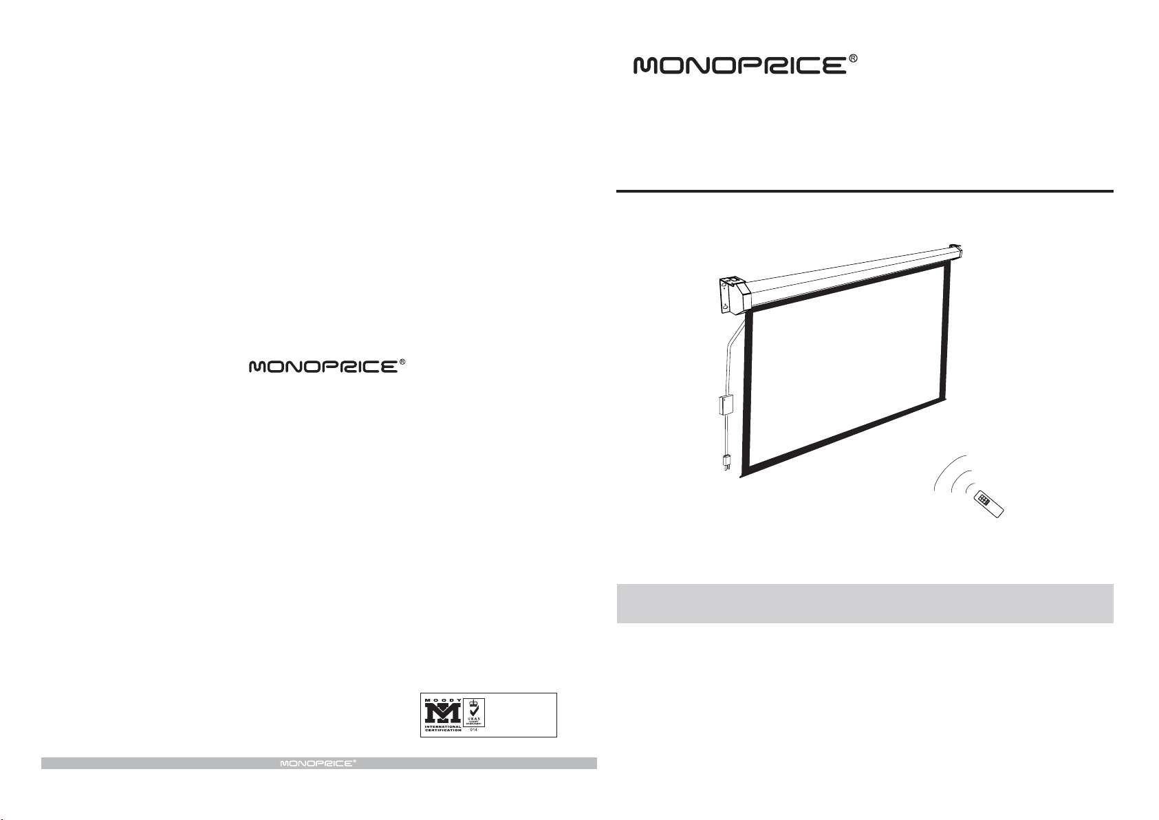
Motorized Projection Screen
Monoprice, Inc.
11701 6th Street, Rancho Cucamonga, CA 91730, USA
www.monoprice.com
ISO9001:2000
International Certification
Thank you for purchasing a Motorized Projection Screen.
Before use, please read instructions carefully. After installation, store instructions for future reference.
Page 2
1
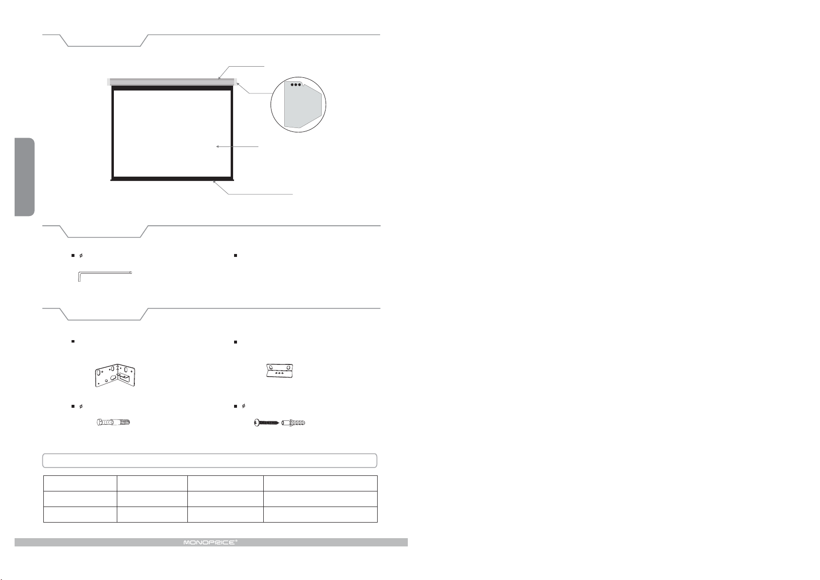
Description
Metal Casin g
End Cap
Scree n Fabric
Rod
Accessories
5 ( 1p c )Al l en K ey
Optional
C1 Moun tin g Bra ck et fo r scr een
si z es u p t o 15 0" ( 2pc s )
10 x 30 m m scr ew a nd an cho r ( 4p cs )
Elegant Motorized Screen Power Specifications
Voltag e( )V Frequ ency( )Hz
230V/1 20V/10 0V 50Hz/ 6 0Hz 90W/8 0 W
230V/1 20V/10 0V 50Hz/60Hz 160W/1 56W
Watts( )W
In s tr uct ion M an ual ( 1 pc )
C2 M o un tin g Bra ck et fo r s cr een s ize s
la r ge r t ha n 1 50" ( 2pc s )
5 40mm Tapping screw & cap ( 8sets )
Appl i catio n
Appl i es up to 15 0" Eleg ant seri es
Appl i es to 180 " a nd up Ele gant ser ies
Page 3

5
Warning s
The ceiling or wall for fixture installation must be secure to prevent the screens from falling.
While installing electrical motors, please hire professionals or our company to ensure safety.
A misconnection may lead to fire or leaks.
Keep all infrared wireless products away from fluorescent lighting as it may cause malfunctions.
Please read the following as any damage to the screen surface will affect the quality of the picture:
1.Avoid contact or touching the screen surface as it may cause scratches or tears.
2.Do not write or draw on the surface
3.Clean the screen with a soft cloth and luke warm water. Do not use any detergent or cleaning products.
Roll up the screen after every use. Ensure that the screen is level when installing; do not pull on the sides
or fold the screen.
To prevent unnecessary damage, the operating and maintenance of the screen should be done by adults.
used
Install ation
This projection s creen should be installed at t he best possib le viewing position for the audience.
Take out all the parts from t he packaging and follow the accessories guideli ne to ensure y ou have
all parts. Th e parts needed will va ry depending on which installation you choose to use. For
installat ion on a wood wa ll or ceiling, use the 5 x 40 scre ws. For installa tion on a drywal l, use the
10 x 30 scr ews with anchors .
Installation without bracket
Wall Mount
Using a t ape meas ure, mea sure the distanc e between the two keyholes on the casing ( Figure 1 ).
According to the measurem ent, use the dri ll to drill id entical holes of the app ropriate size (use a
smaller d rill bit than th e actual screws) on the wall and ensure that it is level ( Figure 2 and 3 ). Screw
in the ap propriate screws, either the 5 x 4 0 for wood wal ls or the 10 x 30 plus anc hors for drywall s,
leaving e nough space at the end to hang the cas ing ( Fi gure 4 ) . To ensure th at the screen is level,
use a leveler to check ( Figure 5 ).
2
Ignoring th e safety warnings m ay
le ad t o i njuri es a nd /o r dama ging
the product .
Do not co nnec t a ny e lec t ric a l
attac hm ents o r r emote co ntrols.
Please cont act our company for
repairs or maintenance.
have any further
Avo id ta ki ng ap art th e
yours el f. Lo ose pa rt s may
the screen to f all.
Do not take apart and replace with unknown parts. If there are any problems, please contact our company.
Product specifications are subject to change.
And if yo u
quest io ns.
fixtu re s
cause
Fixtures should be installed in a secure
place to avoi d accidents or the scr een
falling.
Ro l l up th e s cr een a f te r e ve r y us e .
Leavi ng it hang in g for a long peri od
of time may cause the fabric to loosen.
Refrain from hanging anything on the
screen as it may cause the scre en to
fall.
A
1
A
2
3
4
5
Ceiling Mount
Using a t ape meas ure, mea sure the distanc e between the two rings for hanging on the casing
( Figure 1 ). Accor ding to the measurement, use the drill t o drill identi cal hole s of the appropr iate
size (use a smaller drill bit tha n the actual h ook scre ws) on t he ceiling and ensure that it is level
( Figure 2 and 3 ). Screw in the hook scr ews (not provide d), and lift the screen into the hooks
screws to hang ( Figure 4 ). To ensure th at the screen is level, use a leveler to check ( Figure 5 ).
1
A
A
2
3
4
5
Page 4

Witho ut m ounting b racket in stallat io n
Wall mount
(Suitable forall sizes)
Ceiling mount (Suitable for all sizes)
Hanger
Instructions
SLIGHT UP
UP
STOP
DOWN
SLIGHT DOWN
Remote controller instruction:
1. To retract screen, press "UP".
2. To stop screen, press "STOP".
3. To lower screen down, press "DOWN".
4.5.To retract screen slightly, press "SLIGHT UP".
To lower screen down slightly, press "SLIGHT DOWN”.
3
Bracket Installation
To ensure extra durability and safety installation brackets have been included. The necessity of
brackets will vary depending on the location of installation. For installations of sizes up to 150",
use the C1 bracket. For installations of over 150", use C2.
Installation For Sizes Up to 150"
The screen can be installed either on the wall or with a hidden installation. The wall installation uses 2 holes
on the C1 brackets while the hidden installation uses all 3. Measure the distance between the holes that will
be used on the left and right brackets. Using the measured distance, drill the appropriate holes in the wall
( and ceiling if necessary ). Install the brackets, then lift and match up the screen's end caps to the brackets.
Insert the two screws to join the bracket and screen casing for both sides.
Installation For Sizes Over 150"
Using the C2 brackets, the screen can installed from the ceiling. Measure the distance between the holes
on the left and right brackets. Using the measured distance, drill the appropriate holes in the ceiling. Install
the brackets, then lift and match up the screen's end caps to the brackets. Insert the screws to join the
bracket and screen casing for both sides.
With mo un ting br ac ket insta llation ( )Optio na l
Hidden installation
(Suitable for all sizes)
150 inches and under hidden
wall mount installation
150 inches and up installation
Front view
Remote controller guideline:
1. Working temperature: -20 C - +80 C
2. Protection index: IP30.
3. Batteries: 1.5V x 2pcs, model # AAA.
4. Working under normal polluted environment.
5. Take out batteries if the controller will not be used for a long time.
6. Please change the batteries when signal is weak.
0 0
.
How to install the batteries:
Please change the batteries as below when signal is weak.
1. Turn around the controller, push to pen the cover as guiding arrow.
2. Put the batteries in according to the guide of anode and cathode.
3. Close the cover.
Caution
The controller does not work if mistaking the anode and cathode of
batteries, please correct the direction according to the figure on the
Back vi ew
To avoid overheat ing the motor, do not cont inually retract an d lower the screen for o ver 4 minutes at a time.
If the motor ov erheats, it will need a cool down time of 2 minu tes. The motor does not need any lubricants.
The drop and re tract limit of the scr een is factory prese t to an optimal configuration. Please ask our company
or professi onal to adjust setti ngs to avoid damagin g the motor.
left.
4
Drop Li mit
Retra cti on Li mi t
 Loading...