

Page 1
INSTALLATION INSTRUCTIONS
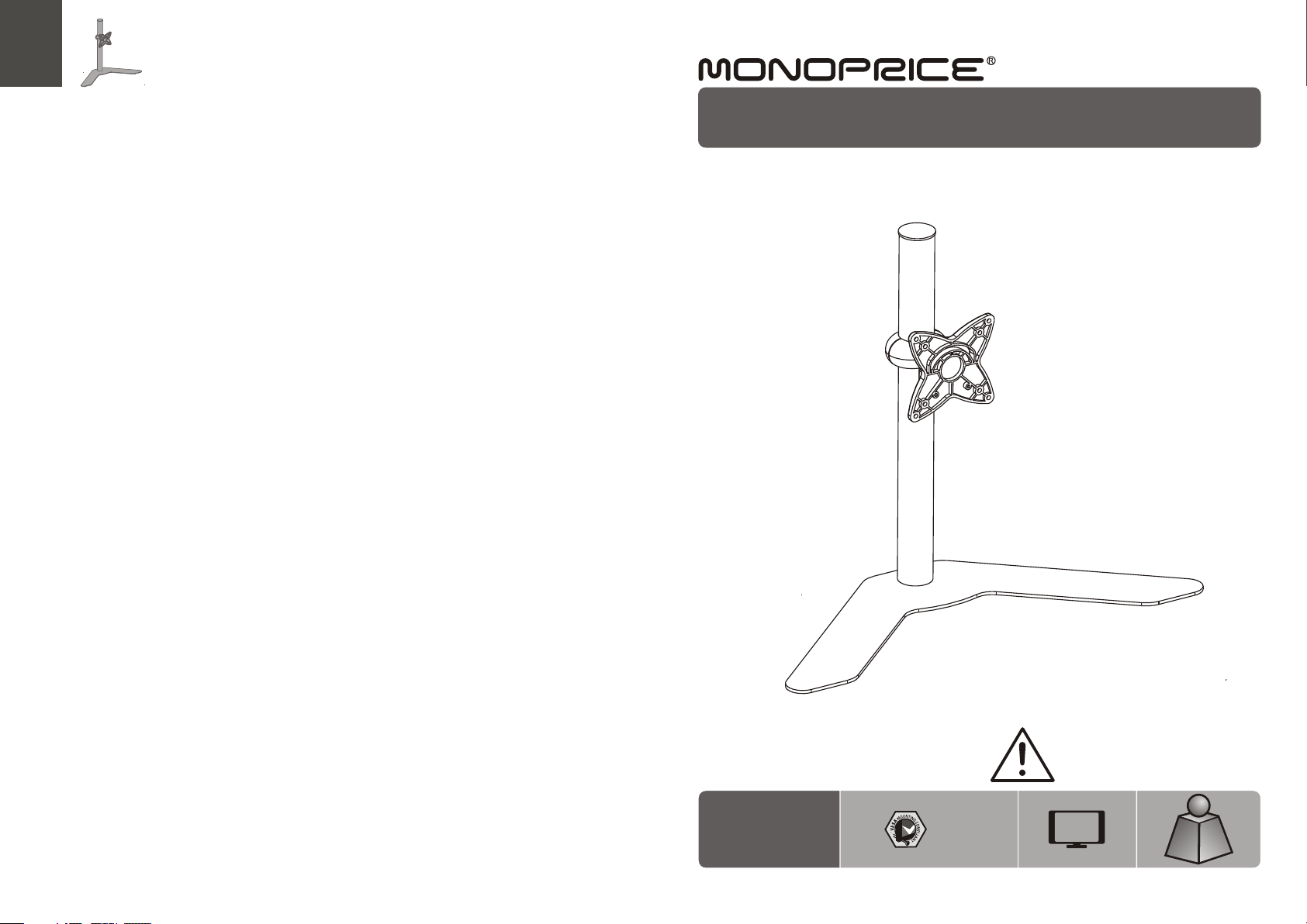
Flat Screen Table Stand
PID 5 970
75x75
100x1 00
CA UTI ON : DO NOT EXCE ED MA XIMUM
LIS TED W EIG HT CAPA CIT Y. S ERIO US
INJURY OR P ROP ERTY DAMA GE MAY
OCCUR!
23"
MAX
15kg
15kg
(33l bs)
(33l bs)
MAX
MAX
ISSUED: NOV. 2012
Page 2
NOTE: Rea d the entire instr uction manual be fore you st art ins tallati on and as sembly.
WARNING
• Do not begin the installation until you have read and understood the instructions
and warnings contained in this installation sheet. If you have any question
regarding any of the instruction or warning, please contact your local distributor.
• This mounting bracket was designed to be installed and utilized ONLY as
specified in this manual. Improper installation of this product may cause damage
or serious injury.
• Make sure that the supporting surface will safely support the combined load of
the equipment and all attached hardware and components.
• Tighten screws firmly, but do not over tighten. Over tightening can damage the
items, greatly reducing their holding power.
• This product is intended for indoor use only. Using this product outdoors could
lead to product failure and personal injury.
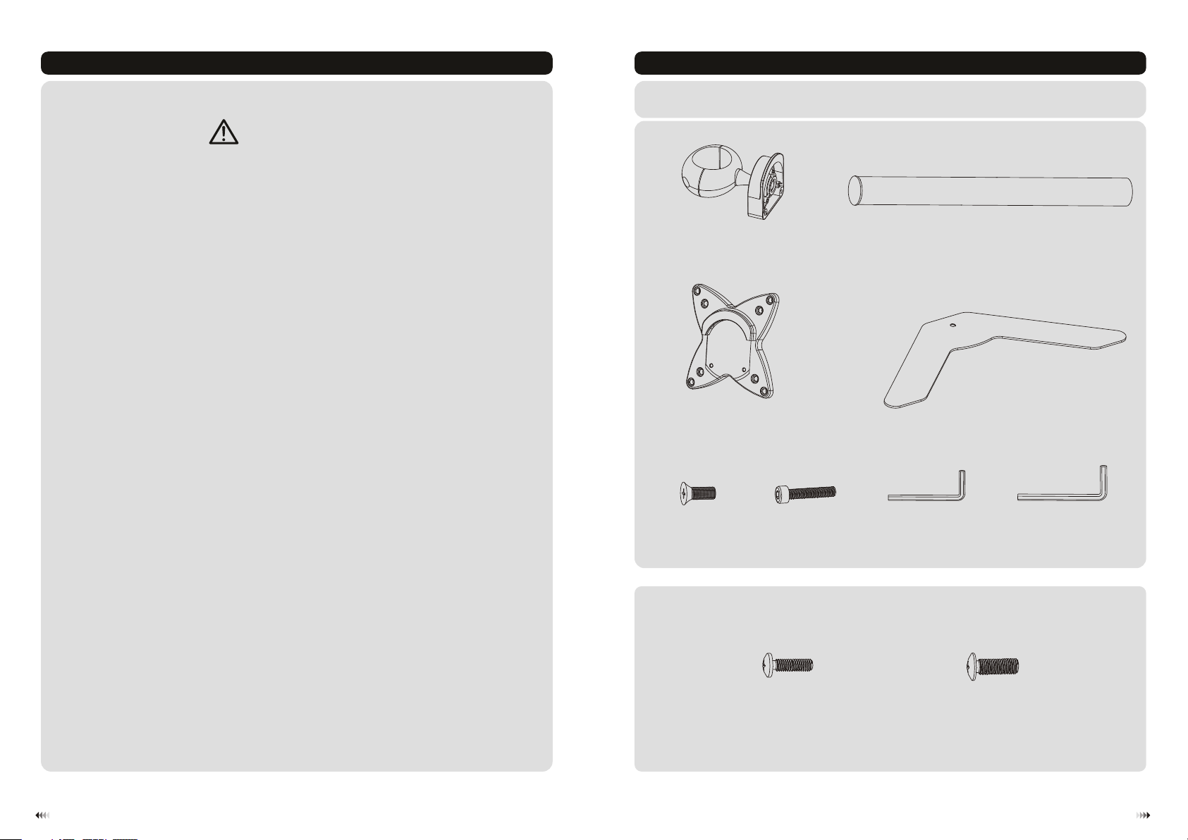
Component Checklist
IMPORTANT: E nsure tha t you h ave r ece ived all pa rts a cco rdi ng to the com pon ent c hec klist pri or to i nst all ing. If
any p art s are m iss ing or faulty, te lep hone your l oca l dis tri butor for a r epl ace men t.
adapt er br ack et
assem bly ( x1)
A
VESA pla te (x 1)
B
pole (x 1)
C
base (x 1)
D
M10x20 (x1)
Package M
E
M5x20 (x2)
F
M4x14 ( x4)
M-A
3mm llen key (x1)A
G
M5x14 ( x4)
M-B
4mm llen key (x1)A
H
21
Page 3

1. Assemble the Table Stand
2. Install the VESA Plate
Attac h the p ole t o the
base us ing t he sc rew.
D
TV
A
C
Screw t he VE SA pla te on to the display.
Tig hten all screws b ut do n ot ov er ti ghten.
E
• Remove the p last ic cover.
• Slide the ad apte r bracket ass embly to a
desired po siti on.Tighten the assembly firmly
using 4mm Allen key.
• Re-attach the pl asti c cover.
H
3. Install the Display
TV
TV
Top of disp lay
M-A/M -B
Lift yo ur di spl ay ca refully and hoo k the
VESA pla te on to th e mou nted head.
3
434
Page 4

F
Inser t two s cre ws in to
mount ing h ole s.
4. Adjustment
G
Depen din g on th e wei ght of the displa y,it may be
neces sar y to ma ke ad justments to th e Bal l Joi nt
Mecha nis m.
60°
+30°
360°
-30°
H
Tig hte n all s crews using 4mm Al len k ey.
Adjus t to de sir ed lo cation or tilt.
Maint ena nce
• Check t hat t he br ack et is s ecure and sa fe to u se at r egu lar intervals (at l eas t eve ry three months ).
• Pleas e con tac t you r dealer if you hav e any q ues tio ns.
65
 Loading...