

Page 1
INSTALLATION GUIDE
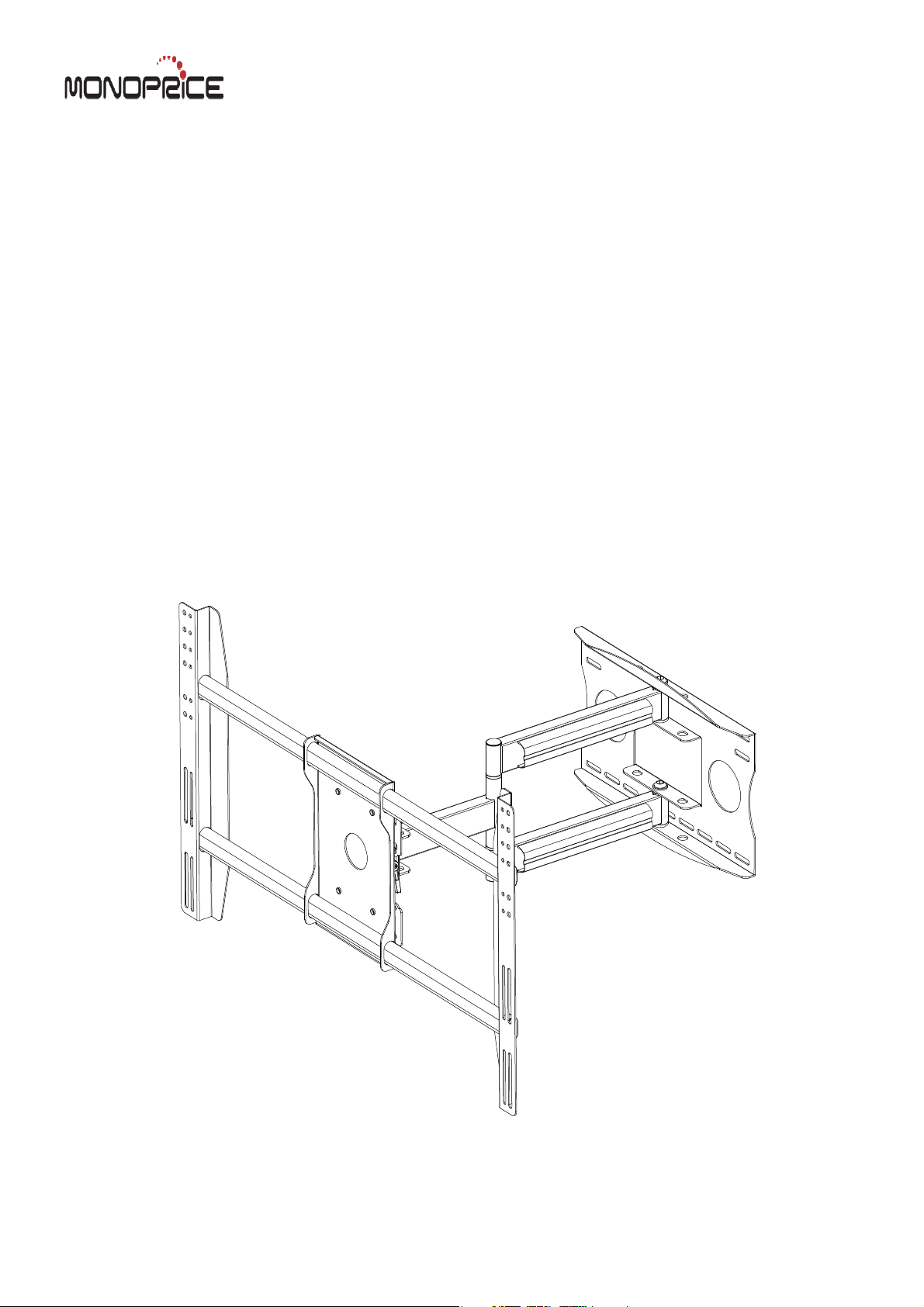
Flat Panel Arm Mount
MHA-700
Support 32" to 52" Screens
Max Load Capacity: 125 lbs (56 kg)
VESA 400x600 compatible
Page 2
WARNING
• Be sure to read this entire manual thoroughly and you fully understand all the instructions and warning before
attempting to begin your installation.
• This product should only be installed by someone who has a basic knowledge of buiding construction,installations and fully
understands these instructions.
• Make sure that the supporting surface will safely support the combined load of the mount, the display and all
attached hardware and components.
• This wall bracket will only supporting flat panel displays(LCD,Plasma).The maximum load capacity is 125 pounds.
• If mounting to a wall of wood stud construction, be sure that mounting bolt are anchored to the center of the
studs.
• Always have someone assist you to lift and position your equipment.
• Tighten screws and bolts firmly, but do not over tighten. Over tightening can damage the items and greatly reduce
their ability to hold. Please refer to suggested torque values where applicable in these instructions.
Tools Needed for Assembly
• stud finder ("edge to edge" stud finder is recommended)
• phillips screwdriver
• ¢6.0 drill bit and ¢10.0 masonry drill bits
Table of Contents
Parts List ........................................................................................................................................................................ 3
Installation to Wood Stud Wall ....................................................................................................................................... 4
Installation to Solid Concrete and Cinder Block .............................................................................................................. 5
Mounting the
Tilt Adjustment and Cord Covers
Attaching adapter plate to Screen
............................................................................................................
............................................................................................................ ........................ ...
2of8
...
6ǃ7
8
Page 3
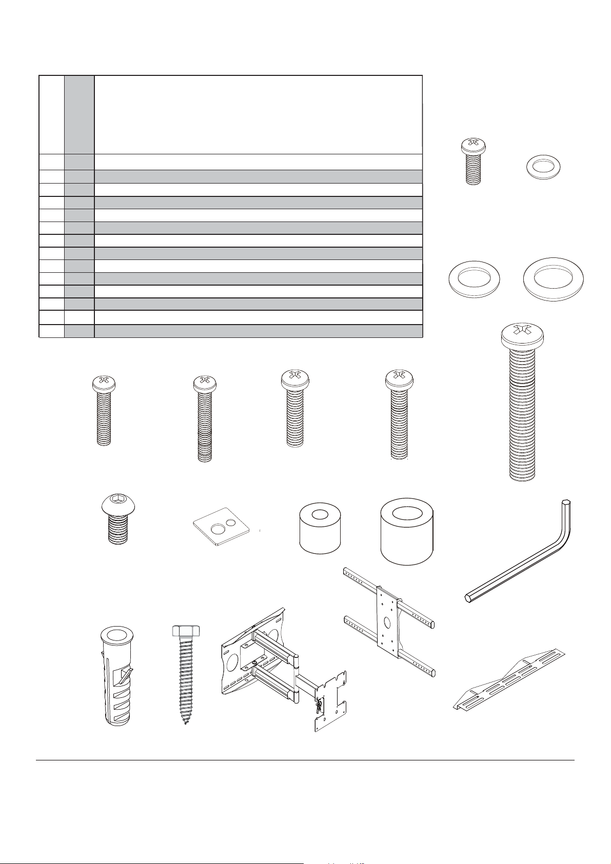
Before you begin, make sure all parts shown are included
with your product.
Parts may appear slightly different than illustrated.
Parts List
Des cription
A
B
C
D
E
F
G
H
J
K
M
N
philips pan head screw / washer
washer
washer
philips pan head screw
philips pan head screw
philips pan head screw
philips pan head screw
philips pan head screw
allen cap screw
I
square spacer
spacer ( 1. 2. )
allen wrench
L
concrete anchor
hex bolt screw
4
M6x12 / 6x13x1.2
4
6
4
4
4
4
4
4
4
4
1
6
6
8.2x1.5x16
8.2x2.0x16
M5x16
M5x30
M6x16
M6x30
M8x45
M8x15
25.65x25.65x2.5
19x8.2x19.6 / 12.7x6.0x12.7
M5
M8x50
M8x70
A
B
C
EF G HD
I
M
JK
N AA(mount)
3 of 8
L
12
$GDSWRU
+RRNV
Page 4

Installation to Wood Stud Wall
WARNING
Make surethat thesupporting surface will safely support the combined load of the equipment and all attached hardware and
components.
Wall arm assembly(AA) must be mounted onto two wooden studs,with center to center distances more than
A
12". Using a stud finder, locate and mark the edges of the wood stud used in mounting this product. Use of an
edge to edge stud finder is highly recommended. Use a level to draw two vertical lines down the center of the stud.
Use wall arm assembly
direction about installation of the wall arm assembly. Drill six 6mm(1/4") dia. holes 3.3"deep.Attach wall arm
assembly (AA) to wall using six hex head screws (N)and six washers
(AA) as template to mark center of holes along the vertical line.Make sure the correct
(C) as shown in fig. A.1
WARNING
Tighten screws so that double stud wall plate is firmly attached, but do not overtighten. Overtightening can damage
the screws,greatly reducing their holding power.
Make sure that mounting screws are anchored into the center of the studs. The use of an "edge to edge" stud finder
is highly recommended.
AA
N
C
w
o
od s
fig.A.1
t
u
d
wal
l
4of8
Page 5

Installation to Solid Concrete and Cinder Block
WARNING
When installing wall plate on cinder block, verify that you have a minimum of 1-3/8" of actual concrete thickness
hole to be used for the concrete anchors. Do not drill into mortar joints! Be sure to mount in a solid part of the block,
generally1" minimum from the side of the block. Cinder block must meet ASTM C-90 specifications. It is suggested that
a standard electric drill on slow setting is used to drill the hole instead of a hammer drill to avoid breaking out the back of
the hole when entering a void or cavity.
Concrete must be 2000 psi density minimum. Lighter density concrete may not hold concrete anchor.
Make sure that the supporting surface will safely support the combined load of the equipment and all attached
hardware and components.
Level and use wall arm assembly(AA) as template
B
to mark center of holes,make sure the correct dire
about installation of the wall arm assembly.
-ction
Drill four
3.3". Insert six concrete anchors( M) in holes flush
with wall as shown in
-mbly
head
fig.
is level,
10 mm dia. holes to a minimum depth of
fig B.1.Place wall arm asse
(AA) over
screws
and
B.2
and
anchors
(N) and
fig.B.4.
tighten all
and secure with six hex
washers
six
Make sure wall the arm assembly
fasteners see fig.B.3.
(C) as shown in
Drill holes and
insert anchors.
Place wall arm
assembly over
anchor and
secure withscrew
and washer.
fig. B.1
fig. B.2
WALL ARM
N
C
in the
concrete
wall
M
WARNING
Tighten hex head bolts
is firmly attached,but do not overtighten. Overtightening
can damage the screws, greatly reducing their holding
power.
so that wall arm assembly
Tighten all
fasteners.
fig. B.3
M
WARNING
Concrete anchors are not intended for attachment to
concrete wall covered with a layer of plaster, drywall,
or other finishing material as shown below. If mounting
to concrete wall covered with plaster/drywall is
unavoidable, plaster/drywall (up to 5/8" thick) must be
counterbored as shown below. Be sure concrete
anchors do not pull away from concrete when tightening screws. If plaster/drywall is thicker than
5/8", custom fasteners must be supplied by the installer.
5of8
N
C
AA
M
fig.
B.4
etercnocdilos
lbrednic
kco
Page 6

C
Mounting the Assembly Adapter Plate to screen
Modify the Adapter Plate
Adaptor Modify the Assembled Adapter Plate
Slide the adapter brackets into Assembled adapter plate slightly.
Place the Assembled Adapter Plate on the back of the display with
one Adapter Bracket aligned with a set of vertical mounting
holes.Then,slide the other Adapter Bracket in or out until it aligns
with the second set of vertical mounting holes.The Adapter should
be horizontally centered on the back of the flat panel display.
Back of Screen
Adaptor and hooks
Adapter
Bracket
Adaptor and hooks
and tighten it with
Use four M6x12 screws and four washers
Phillips Head Screw Driver.
Square
spacer
Mounting
Screw
M6&M8
Hole
M5 Hole
washers
(13x6x1.2)
M6x12
Screw
Adaptor and hooks
Note:
Recessed Mounting Holes.
If the mounting holes are recessed
into the back of the display, use the
supplied spacers to pack the
recessed hole. If the mounting
screw is M5&M6,use the
Spacers1.(K.1.)If the mounting screw
is M8,use the Spacers 2.(K.2.)
Ensure that the brackets are
securely fixed to the display.
Top of
Display
*For screen with a hole
pattern in a pocket,spacers
go between Assembly
Adapter Plate and screen.
6 of 8
Spacers
Page 7

For Flat Back Screen
fig C.1 fig C.2
SCREEN
SCREW
SCREEN
SPACER
OR
AA(mount)
Select the small,medium,large or extra large screws from the baffled .Fastener pack then attach
screen brackets(AA) to screen following figure C.1 or C.2 on page 7.
Attach Assembly Adapter Plate to Assembly Arm
top screw
Iron spacer
M8x15mm
screw bolt
.25"
AA(mount)
1. Insert two M8x15mm screws
and two metal washers into swivel box
on Assembly Adapter Plate as above
shown.
Leave approx. 1/4" of exposed thread.
2. Lift the display and hook it
over the mounting head by lowering
the exposed portion of the top screws
down the open key slots.
SCREW
NOTE:This procedure will require
two persons.Ensure that the arm is
set to its maximum negative tilt prior
to attaching the display
7 of 8
washers
3. Once in position, attach the bottom
two M8x15mm screws and two
washers to secure the display to the
mounting head using M5mm Allen
Wrench.
M8x15mm
screw
Page 8

D
Tilt Adjustment and cord Coves
Tilt Adjustment
1.Loosen Tiltlevers(Only enough to
allow controlled adjustment)
2. Adjust Tilt
3. Lock Tilt Levers(Tighten)
4. Once Tilt Levers are locked,the
without loosening ortightening the unit
by pulling the levers outwards and then
repositioning them to a vertical,less
obtrusive position.
Cord Covers
WARNING:
Before removing
your
display,ensure
the display has a
negative Tilt and
Tilt Lever is
LOCKED!
Tighten
position of the levers can be adjusted
Loosen
Tiltlever
Install Cord Covers as shown.
NOTE:Be sure to leave enough
slack to allow for movement of
the arms.
Cord Covers
8 of 8
 Loading...