

Page 1
A
B
C
D
E
F
G
H
I
J
K
L
M
N
O
Installation Guide
Monoprice Flat Panel Display Adjustable Wall Mount
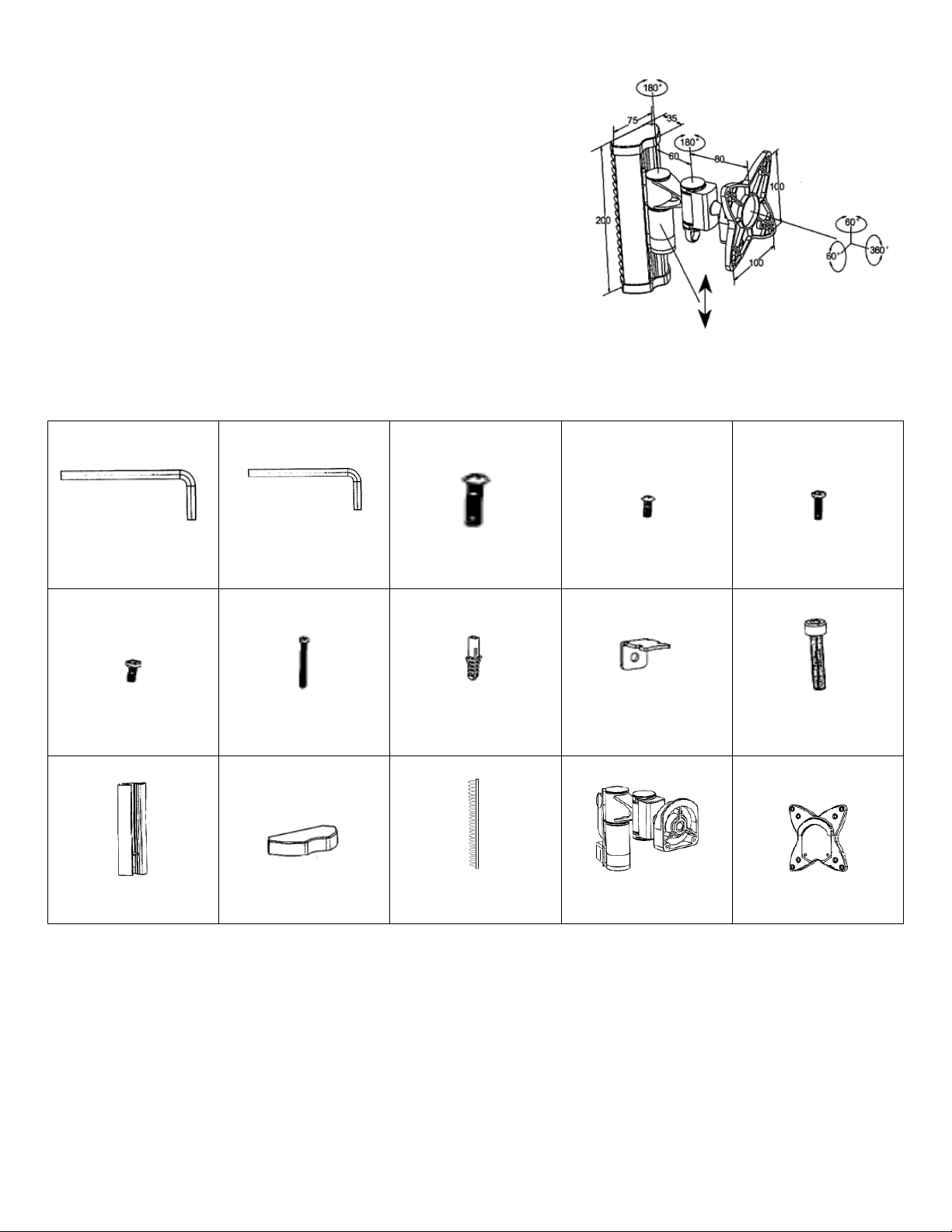
VESA 75/100mm
Max Weight: 33lbs/15kg
TV to Wall: Min 128mm, Max 188mm
Package Contents:
Please review before starting to make sure no parts are missing. If any parts are missing, please
contact us to have replacement parts sent to you.
4mm Allen Key
X 1
3mm Allen Key
X1
M4x14mm
X 4
M4x10mm
X 4
M5x14mm
X 4
M5x10mm
X 4
X 4
M5x50mm
X 4
8x36mm Concrete Anchor
“L” Bracket
X 1
M5x20mm
X 2
X 1
Wall Bracket
Wall Bracket Cap
X 2
Cable Mgmt Guide
X 2
Arm Assembly
X 1
Display Mounting Plate
X 1
Introduction:
Thanks for purchasing the Monoprice MCD-133 adjustable flat panel display wall mount. The MCD133 is designed to be attractive, durable, easy to install and provide you with years of reliable service.
The mount can be installed on to solid concrete or wood studs. If you plan to install it onto any other
type of wall surface, please consult the advice of a professional installer.
Page 2
Installation:
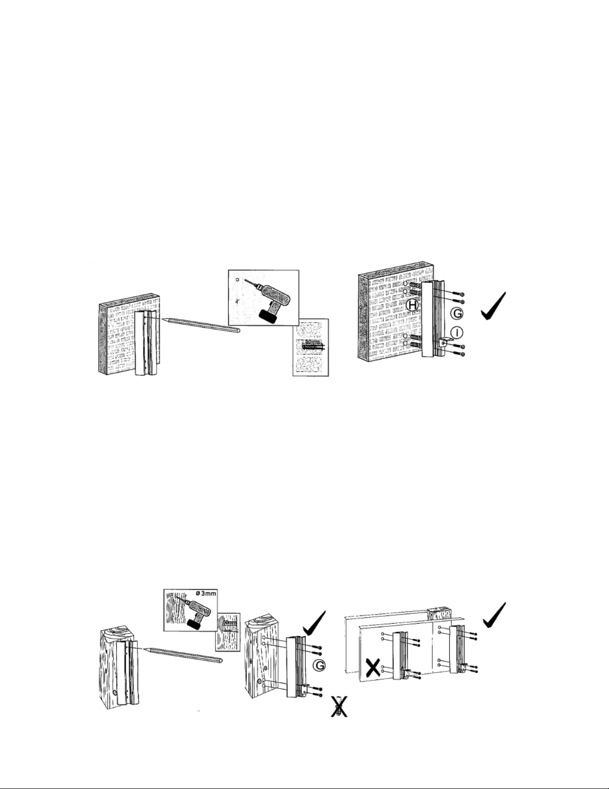
Step One:
Concrete:
1a. If you are installing on to concrete or solid brick, you will need to use the included concrete
anchors (part H). Use a level to positions the wall bracket (part K) at the place on the wall you want
to install the mount and make sure the bracket is vertically straight. Holding the wall bracket to the
wall, use a pencil to mark the 4 points the mount will attached to the wall. Drill 8mm pilot holes
approximately 50mm deep. Insert the anchors into each of the holes. Line up the wall bracket with
the pilot holes and attach the bracket to the wall with the lag bolts (part G). Before inserting the 2
bottom lag bolts, insert the “L” bracket (part I) up through the groove in the wall bracket from the
bottom aligning it as shown in the illustration. Use the top of the two bottom bolts to secure the “L” to
the bracket and wall.
Figure 1a
Wood Studs:
1b. If you are installing on to a wood stud wall, you will need to use a stud finder to locate the location
of a stud in the wall. Mark your stud. Use a level to positions the wall bracket (part K) along the stud
and make sure the bracket is vertically straight. Holding the wall bracket to the wall, use a pencil to
mark the 4 points the mount will attached to the wall. Mount directly over a stud. Never mount directly
to unsupported drywall. Drill 5mm pilot holes approximately 50mm deep int o the stud. Line up the
wall bracket with the pilot holes and attach the bracket to the wall with the lag bolts (part G). Before
inserting the 2 bottom lag bolts, insert the “L” bracket (part I) up through the groove in the wall bracket
from the bottom aligning it as shown in the illustration. Use the top of the two bottom bolts to secure
the “L” to the bracket and wall.
Figure 1b
Page 3

Step Two:
Figure 2
Figure 3
Figure 4
Figure 5
Attach the bottom wall bracket cap (part L) and slide the cable
management guides (part M) into their appropriate groves on
the wall bracket if they are not already installed.
Step Three:
Make sure the arm assembly (part N) is oriented correctly.
The arm should extend out from the top of the cylinder that
attaches to the wall bracket and the plastic snap clips should
be on the bottom cylinder. Slide the wall bracket attachment
arm of the arm assembly on to the wall bracket into the center
grove from the top opening of the wall bracket. Slide the arm
assembly down keeping it tilted at an upward angle till you
bring it to the position on the wall bracket you desire.
Step Four:
Snap the bottom snap clip into the wall bracket grove. It
should click into place and the arm assembly should be
upright and not able to slide up and down once it is snapped
properly in place.
Step Five:
Attach the top wall bracket cap (part N).
Page 4

Step Six:
Figure 8
Figure 7
Figure 6
After having prepped your flat panel display by removing any table
top stands as instructed in the manual for your display, attach the
display mounting plate (part O) to the back of your display. Make
sure it is in the correct orientation. The “U” shaped lip should be on
the top of the plate pointing downward. Use four of the machine
screws included with the mount (Part C, D, E or F) or included with
your display to attach the plate to the back of the display. If none of
the included screws fit, contact the manufacturer of your display to
find out the appropriate size needed and purchase them at a local
hardware store.
Step Seven:
Hook the lip of the display plate onto the head of the arm assembly. Align
the two bottom holes on the head to the holes on the plate and attach them
with the allen bolts (Part J) and tighten with the included Allen key (part A)
Step Eight:
Adjust your display to the desired position. Once in the desired position, use the Allen key (Part B) to
tighten the three smaller allen bolts securing the ball retention ring to secure your display’s position.
Congratulations, You’re Done!
The display should be able to swivel freely side to side on it’s swing arm but should hold it’s tilt and
rotational position. Enjoy.
 Loading...