

Page 1
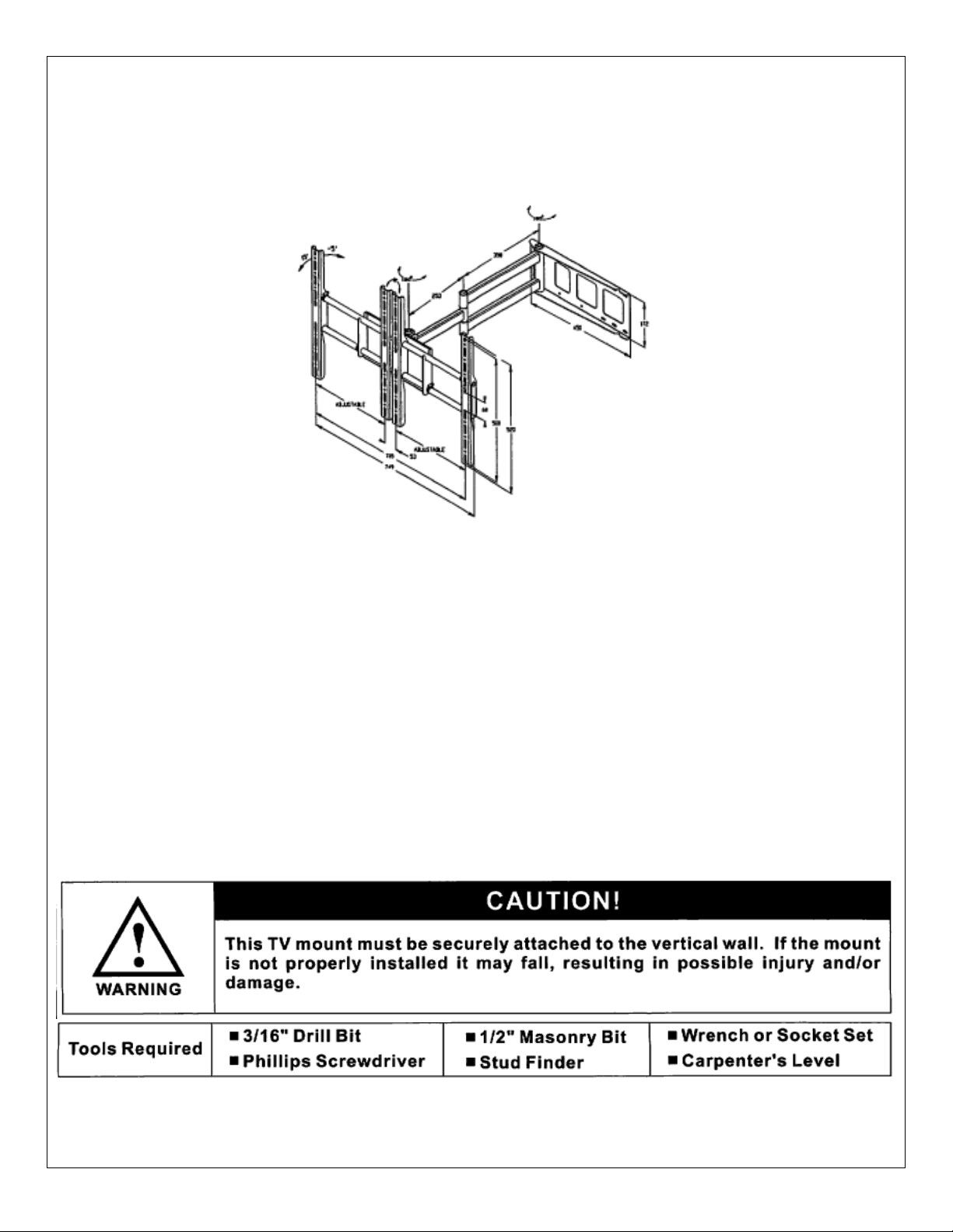
Monoprice Adjustable Tilt/Swivel Flat Panel Wall Mount
Model MLB-WA8 (PID# 4562)
VESA Compliant up to 700x500
Max Weight: 110lbs
Installati on Instructions
UNPACKING INSTRUCTIONS
• Carefully open the carton , remove the contents and lay them out on cardboard or other protec tive surface to avoid
damage.
• Check the contents against the supplied parts list on the next page to assure that all components were received
undamaged. Do not use any damaged or defective parts.
IMPORTANT SAFETY INFORMATION
Install and use this device with c are. Please read this entire m anual before atte mpting installat ion and carefull y follow all
instructions contained herein. Use proper safety equipment during installation.
Please call a qualified installation contractor for help if you:
• Don’t understand the instructions in this manual or have any doubts about the safety of the installation.
• You are uncertain about the nature of your wall.
Do not use this product f or any purpose or in any conf iguration not explicitly specif ied in these instruction s. Monoprice
hereby disclaims any and all liability for injury or damage arising from incorrect assembly, incorrect mounting or any
incorrect use of this product.
Note: The mounting components and hardware supplied in this pack age are not designed for installation to wall with
steel studs or to cinder block walls. If the hardware you need for your installation is not included, please consult your local
hardware store for proper mounting hardware for this application.
Page 2
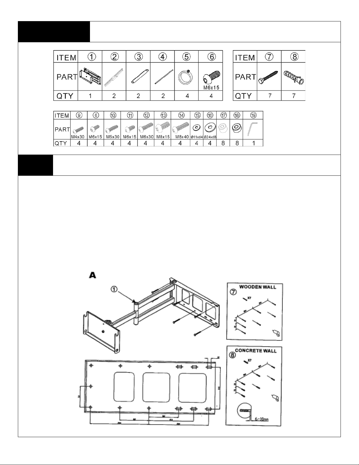
Supplied Parts List
be mounted to two wood studs. Use a stud finder to locate two adjacent studs. It is a good idea to verify
drill a 2.5” deep hole at the desired height in each stud using a 3/16” drill bit.
Step 1 Mounting the Wall Plate to the Wall
Brick, Solid Concrete and Concrete Block Mounting:
Use the Wall Plate (part 1) as a template t o mark 7 hole locations on the wall. Three in the top row of slots, three more in the bottom
row and the last between the top and bottom screws on the left hand side. Make sure these holes are level. Pre-Drill these hol es with
a ½” masonry bit to at least 2.5” in depth. Insert a Concrete Anchor (part 8) into each of these holes. Make sure the anchor is seated
completely flush with the concrete surface even if there is a layer of drywall or the other material in front. Attach the Wall Plate to the
wall using 7 Lag Bolts (part 7), as shown in the diagram.
Wood Stud mounting:
The Wall Plate (part a) must
where the studs are located with an awl or thin nail. PreMake sure these holes are in the center of the studs and level with each other. Use the Wall Plate as a template to mark the location of
the other holes in each stud. Drill pilot holes at each of the marked locations. Attach the Wall Plate to the wall using the 5 Lag Bolts
(part 7).
Page 3

Step 2 Mounting the Monitor Bracket Frame to a TV
rtical TV mounting rails to the television, please determine which setup is appropriate for your
Case A.
Case B.
The arrangement of the TV mounting rails (part 2) will depend on the horizontal distance between the mounting holes on the back of
your television. Before attaching the ve
television in order to determine the proper place men t of the retent ion cla mp s (part 5).
If the mounting holes on your television are 54 to 235mm.
TV mounting rails will go inside of the extension arm plate and
retention clamps go on outside of the rails.
Case C.
If the mounting holes on your television are 346-683mm.
TV mounting rails will go outside the extension arm plate and the
retention clamps go outside the rails.
If the mounting holes on your television are 235-257mm.
TV mounting rails will go inside the extension arm plate and
retention clamps go on the inside of the rails.
Case D.
If the mounting holes on your television are 683-705-257mm.
TV mounting rails will go outside the extension arm plate and the
retention clamps go on the inside of the rails.
Make sure one of the machine bolt sizes fits the
mounting holes on your television.
Once you have selected the correct size bolt,
attach the rails to the television with the
retention clamps slid onto the horizontal frame
rod (part 4) at the appropriate location. Use
four machine screws to attach the rails to the
television, 2 per rail.
Page 4

Step 3 Attaching the TV to the Mounting Arm
Slide the bottom horizontal frame rod (part 4) through
the holes on the bottom of the extension arm mounting
plate. Slide on the retention clamps (part 5) on their
appropriate positions as illustrated in the diagram based
on your selection for the appropriate case scenario in
step 2.
Warning: Some TVs may require two people to lift! Monoprice is not responsible for personal injury or product damage.
With assistance, lift your television up onto the mounting arm. The bottom of
the TV mounting rails that are already attached to the TV will hook onto the
bottom rod already on the extension arm plate and the top frame rod already
on the TV will hook onto the top of the mounting plate as shown in the
diagram. Secure the installation by attaching the mounting frame end plates
(part 3) to the ends of the frame rods with the M8 machine screw (part 6).
Center your TV and tighten the retention clamps to hold the frame in position
and kept the frame from sliding.
Step 4 Adjusting the TV
Thanks for Choosing a Monoprice Wall Mount. Enjoy!
 Loading...