

Page 1

6-Zone Home Audio Passive Multizone Controller Preamp Kit
P/N 39261
User's Manual
Page 2

2
SAFETY WARNINGS AND GUIDELINES
Please read this entire manual before using this device, paying extra attention to these safety
warnings and guidelines. Please keep this manual in a safe place for future reference.
• This device is intended for indoor use only.
• Do not expose this device to water or moisture of any kind. Do not place drinks or other
containers with moisture on or near the device. If moisture does get in or on the device,
immediately unplug it from the power outlet and allow it to fully dry before reapplying power.
• Do not touch the device, the power cord, or any other connected cables with wet hands.
• Do not subject the product to extreme force, shock, or fluctuations in temperature or
humidity.
• Do not expose this device to excessively high temperatures. Do not place it in, on, or near a
heat source, such as a fireplace, stove, radiator, etc. Do not leave it in direct sunlight.
• This device ventilates excessive heat through the slots and openings in the case. Do not block
or cover these openings. Ensure that the device is in an open area where it can get sufficient
airflow to keep from overheating.
• Do not place or install this device in an area where it can be exposed to excessive amounts of
dust, humidity, oil, smoke, or combustible vapors.
• Do not place or install this device in an area that lacks proper ventilation, such as an enclosed
cabinet or closet.
• Prior to operation, check the unit and power cord for physical damage. Do not use if physical
damage has occurred.
• Before plugging the unit into a power outlet, ensure that the outlet provides the same type
and level of power required by the device.
• Unplug this device from the power source when not in use.
• Take care to prevent damage to the power cord. Do not allow it to become crimped, pinched,
walked on, or become tangled with other cords. Ensure that the power cord does not present
a tripping hazard.
• Never unplug the unit by pulling on the power cord. Always grasp the connector head or
adapter body.
• Ensure that power is turned off and disconnected before making any electrical connections.
• Clean using a soft, dry cloth only. Do not use chemical cleaners, solvents, or detergents. For
stubborn deposits, moisten the cloth with warm water.
• This device has no user serviceable parts. Do not attempt to open, service, or modify this
device.
Page 3

3
INTRODUCTION
This 6-Zone Home Audio Passive Multizone Controller Preamp Kit is a functional 6x6 audio matrix
controller which can distribute any audio input to any or all outputs. It features 6 line level audio
inputs, 6 stereo preamplifier outputs, and 6 remote keypads to control each output zone. It can be
daisy chained with up to two additional units to enable up to 18 output zones. In addition to keypad
control, it can be controlled using a computer connected to an Ethernet network or using RS-232
control commands. It has a 12V trigger output for each zone, that allows it to activate a trigger
device, such as curtains or a projection screen, whenever the zone is activated.
FEATURES
• 3 stereo RCA, 2 stereo 3.5mm, and 1 digital optical inputs
• 6 output zones
• Includes a keypad for each zone to allow for remote control of the zone
• Includes an IR remote control
• 12V trigger output for each zone
• Each keypad has an IR receiver to allow for remote control of the source using an IR
transmitter (not included)
• Can be controlled over an Ethernet network connection using the built-in web GUI
• Can be controlled over an RS-232 direct connection using RS-232 control commands with a
home automation system
• Can be controlled using a free Android™ or iOS® app
• Can be daisy chained with up to 2 additional controllers to allow for up to 18 output zones
CUSTOMER SERVICE
The Monoprice™ Customer Service department is dedicated to ensuring that your ordering,
purchasing, and delivery experience is second to none. If you have any problem with your order,
please give us an opportunity to make it right. You can contact a Monoprice Customer Service
representative through the Live Chat link on our website www.monoprice.com or via email at
support@monoprice.com. Check the website for support times and links.
Page 4
4
PACKAGE CONTENTS
Please take an inventory of the package contents to ensure you have all the items listed below. If
anything is missing or damaged, please contact Monoprice™ Customer Service for a replacement.
1x Multizone Controller with 2x Rack-Mount Ears and 12x Terminal Blocks
1x IR Remote Control
1x Expansion Ribbon Cable
1x Keypad Connection Hub with Decora Wall Plate
6x Keypad Controllers with Built-in IR Receiver and Decora Wall Plates
1x AC Power Adapter
1x User's Manual
PRODUCT OVERVIEW
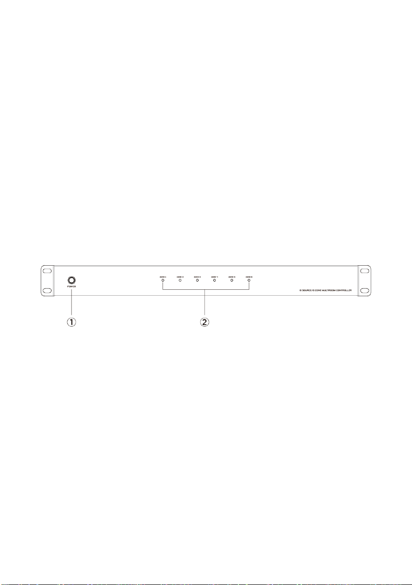
Controller Front Panel
1. POWER: Depress the POWER button to turn the system on or off. When the controller is
powered on, the individual zones will remain in standby until the zone Keypad is activated.
2. ZONE #: Six LED indicators to show the status of each zone. An LED will illuminate Blue when
the zone is in Standby mode, White when the zone is Active, and Blue and White alternately
when the zone is Muted.
Page 5
5
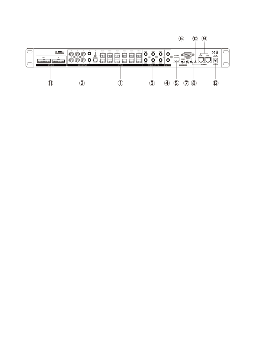
Controller Rear Panel
1. OUTPUTS: Six stereo preamplifier output terminal block pairs to connect to the inputs of
external amplifiers or powered speakers.
2. SOURCE INPUTS: Three stereo line level RCA inputs, two stereo 3.5mm TRS line level inputs,
and one digital optical input for connecting six audio source devices.
3. TRIGGER OUTPUTS: Six 3.5mm trigger connectors for connecting to triggerable devices, such as
curtains or projection screens. Each trigger output sends a 12V trigger when the corresponding
zone is activated.
4. IR EMITTER: Two 3.5mm connectors for connecting IR transmitters (not included) to control the
source devices.
5. KEYPADS: RJ45 jack for connecting the included Keypad Connection Hub.
6. MASTER/SLAVE SWITCH: Three position slide switch to set the Master/Slave mode for this
controller. When additional controllers are connected, eac h controller must be set to a
different mode. When only a single controller is used, the switch should be set to the MASTER
position.
7. AGC SWITCH: Slide switch to turn Automatic Gain Control on or off. When AGC is set on, the
level of the individual inputs is boosted to a preset level, which ensures volume uniformity.
8. RS232: 9-pin RS-232 serial connector for connecting a computer for RS -232 control. The switch
between the RS232 and ETHERNET labels determines which control source to use.
9. ETHERNET: Two RJ45 LAN connectors for connecting an Ethernet network for control using the
built-in web GUI. The switch between the RS232 and ETHERNET labels determines which
control source to use. Note that the images in this manual incorrectly label these ports LAN2
and LAN1. They are actually labeled LAN and TO DEVICE, from left to right.
10. RESET BUTTON: Press the RESET BUTTON to reset the controller to its factory default settings.
11. EXPANSION: IN and OUT terminals for connecting the included Expansion Ribbon Cable to
connect additional controllers.
12. DC IN: DC barrel connector for connecting the included AC Power Adapter.
Page 6
6
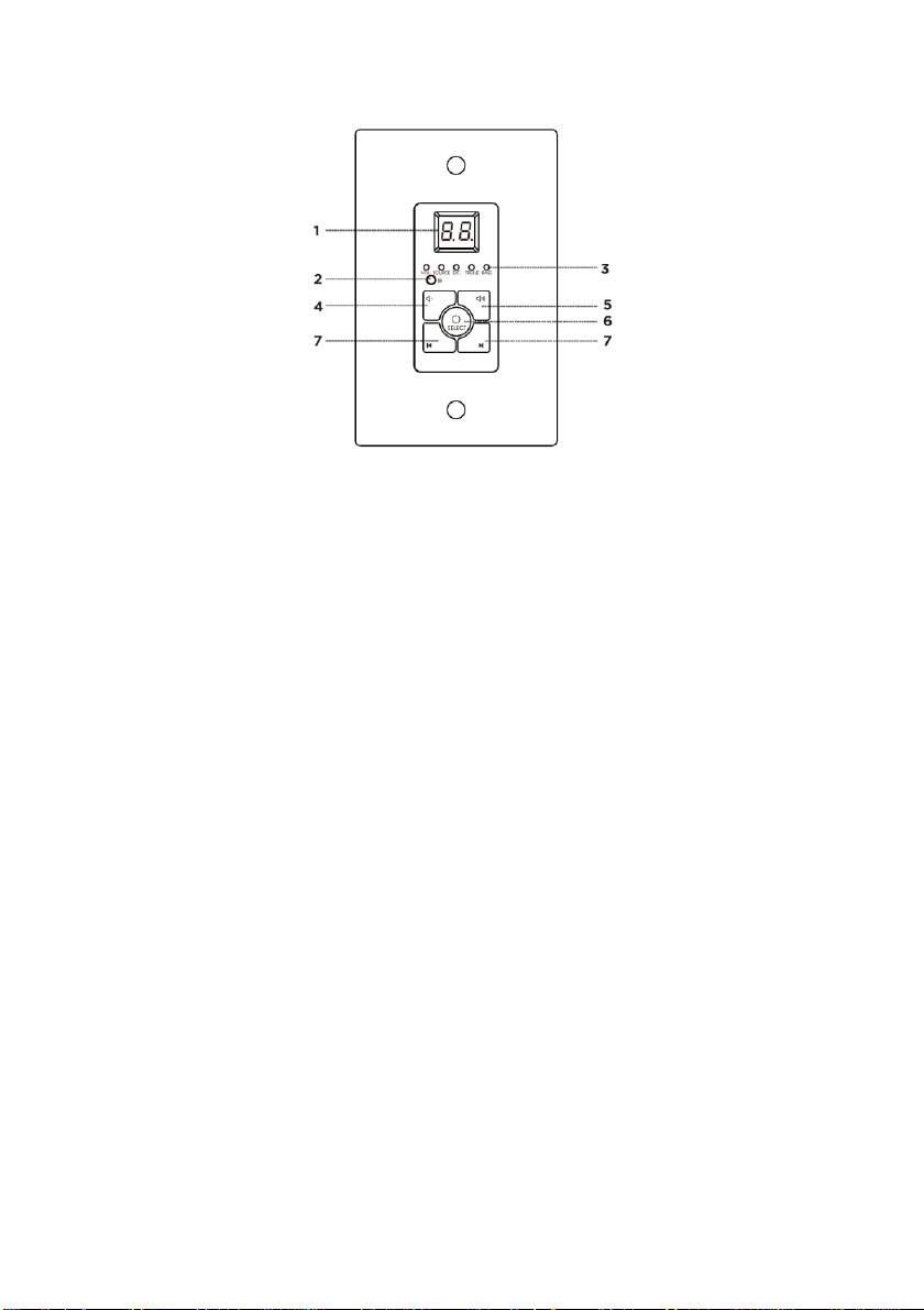
Keypad
1. NUMERIC DISPLAY: LED numeric display, which shows the Volume level, Selected Source
number, Mute status, Treble level, and Bass level, depending on the current Keypad mode.
2. IR: IR receiver.
3. STATUS LEDS: Five LEDs to indicate the Keypad mode.
• When VOL. is illuminated, the DOWN and UP buttons control the volume level and the
NUMERIC DISPLAY shows the volume level.
• When SOURCE is illuminated, the NUMERIC DISPLAY shows the selected input source
number.
• When EXT. is illuminated, the DOWN button turns audio mute off, the UP button turns
audio mute on, and the NUMERIC DISPLAY indicates the mute status.
• When TREBLE is illuminated, the DOWN and UP buttons control treble response and the
NUMERIC DISPLAY shows the treble value.
• When BASS is illuminated, the DOWN and UP buttons control bass response and the
NUMERIC DISPLAY shows the bass value.
4. DOWN: Button to decrease Volume, Treble, or Bass and to turn mute off, depending on the
Keypad mode.
5. UP: Button to increase Volume, Treble, or Bass and to turn mute on, depending on the Keypad
mode.
6. SELECT: Press and hold the SELECT button for several seconds to turn the zone on or off.
Momentarily press the SELECT button to cycle through the keypad modes. The STATUS LEDs
indicate the currently selected Keypad mode.
7. SOURCE SELECT: Use the left button to cycle backward through the available input sources
and the right button to cycle forward through the available input sources.
Page 7
7
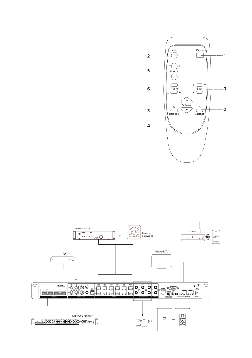
Remote Control
1. Power: Momentarily press the Power button to
turn the zone on or off.
2. Mute: Momentarily press the Mute button to turn
audio muting on or off.
3. Balance: Momentarily press the L Balance button
to adjust the stereo balance to the left and the R
Balance button to adjust the stereo balance to
the right.
4. Volume: Momentarily press the Volume+ button
to increase the volume level and the Volume-
button to decrease the volume level.
5. Source: Momentarily press the Source+ button to
cycle forward through the available inputs and
the Source- button to cycle backward through
the available inputs.
6. Treble: Momentarily press the Treble+ button to
increase treble response and the Treble- button to decrease treble response.
7. Bass: Momentarily press the Bass+ button to increase bass response and the Bass- button to
decrease bass response.
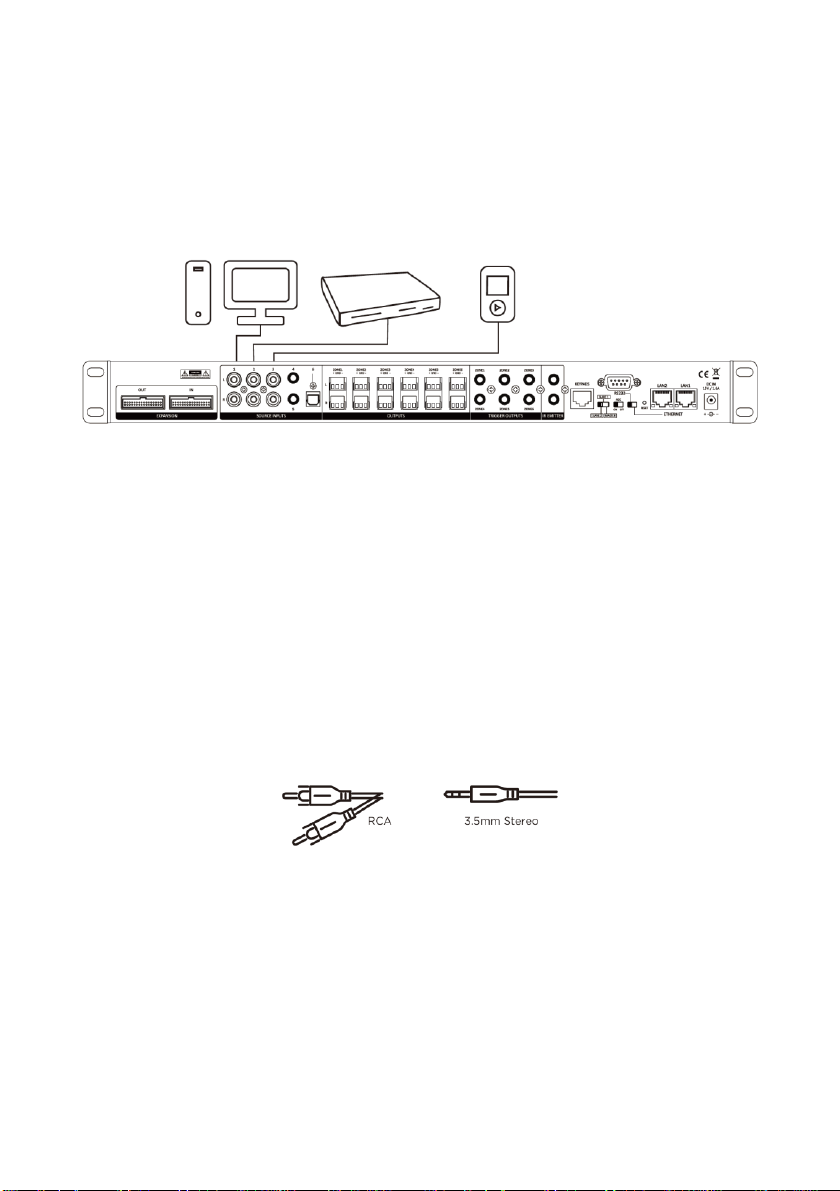
SAMPLE CONNECTION DIAGRAM
Page 8
8
INSTALLATION
IMPORTANT! Ensure that each device to be connected is turned off and disconnected from its power
source before making any electrical connections.
Connecting the Source Devices
1. Set the MASTER/SLAVE switch on the Controller to the MASTER position.
2. Using a stereo RCA cable (not included), plug one end into the SOURCE INPUTS 1, 2, or 3 RCA
inputs on the Controller, then plug the other end into the stereo RCA output of an audio
source device. Repeat for up to two additional source devices.
3. Using a stereo 3.5mm TRS cable (not included), plug one end into the SOURCE INPUTS 4 or 5
3.5mm jacks on the Controller, then plug the other end into the 3.5mm headphone output on a
mobile device. Repeat for up to one additional device.
Note: If you have more than three audio source devices with stereo RCA output, you can use a
stereo RCA to 3.5mm audio cable (not included) to connect the device to the SOURCE INPUTS
4 or 5 inputs on the Controller. If you have more than two devices with stereo 3.5mm output,
you can use a stereo RCA to 3.5mm cable (not included) to connect the device to the SOURCE
INPUTS 1, 2, or 3 RCA inputs on the Controller.
4. Using a digital optical audio cable (not included), plug one end into the SOURCE INPUTS 6
optical input on the controller, then plug the other end into the optical audio output of an
audio source device.
Page 9

9
Connecting the Keypads
Note that all Ethernet cables used should be wired to either the T-568A or T-568B standard. We
recommend using the T-568B standard, as it is the most common type. Prebuilt Ethernet cables from
Monoprice™ are always wired to the T-568B standard.
1. Using an Ethernet cable (not included), plug one end into the KEYPADS jack on the Controller,
then plug the other end into the input on the front of the Keypad Connection Hub. For best
results, this cable should be no longer than 7-10 feet.
Note if the Ethernet cables are to be run through the walls, they must be rated for in-wall use.
2. Using an Ethernet cable (not included), plug one
end into one of the six Keypad outputs on the
rear of the Keypad Connection Hub, then plug the
other end into the input on one of the Keypads,
as shown in the image to the right. Repeat for the
other five Keypads.
3. Use the DIP switches on the rear of each Keypad to assign a different zone to each Keypad,
according to the settings shown in the following image.
Page 10

10
Connecting IR Transmitters
The Controller features two IR EMITTER outputs, to which you can connect up to two IR transmitters.
Plug an IR transmitter (not included) into one of the IR EMITTER jacks on the rear of the Controller,
then position the transmitter bulb where it can send signals to the IR receiver on one of th e source
devices. You can then use the source device's remote control to control the source from any zone
that has that source device selected.
Connecting Multiple Controllers
You can daisy chain up to two additional controllers, allowing you to distribute any of the 6 inputs on
the Master Controller to up to 18 individual zones. Perform the following steps to connect additional
controllers.
1. Using the included Expansion Ribbon Cable, plug one end into the EXPANSION OUT port on
the Master Controller, then plug the other end into the EXPANSION IN port on the Slave 1
Controller.
Page 11

11
2. (Optional) Plug a second Expansion Ribbon Cable
into the EXPANSION OUT port on the Slave 1
Controller, then plug the other end into the
EXPANSION IN port on the Slave 2 Controller.
3. Set the SLAVE/MASTER switch on the Master
Controller to the MASTER position.
4. Set the SLAVE/MASTER switch on the Slave 1
Controller to the SLAVE 1 position.
5. If you have a third Controller, set the
SLAVE/MASTER switch on the Slave 2 Controller to the SLAVE 2 position.
EXTERNAL CONTROL
The Controller features the ability to be controlled by a computer or APP connected to an Ethernet
network or by a computer connected to the RS-232 port.
Ethernet Control
The Controller features two RJ45 Ethernet jacks, which can be connected to an existing Ethernet
network and other network devices, such as a smart TV. When one of the ports is connected to an
Ethernet network, the two ports function as an Ethernet switch. Perform the following steps to
connect the controller for Ethernet control.
1. Set the RS232/ETHERNET switch on the Controller to the ETHERNET position. Ensure that the
MASTER/SLAVE switch is set the MASTER position.
2. Using an Ethernet network cable (not included), plug one end into the LAN1 port on the
Controller, then plug the other end into a Wi-Fi® router or Ethernet switch connected to the
network. Note that to use the mobile app for control, the network must have a Wi-Fi
connection.
3. (Optional) Using a second Ethernet network cable (not included), plug one end into the LAN2
port on the controller, then plug the other end into a network device, such as a smart TV.
IMPORTANT! Do not connect a computer directly
to the Controller! The Controller must be
connected to an existing Ethernet network or
other network devices.
4. Turn the Controller and your computer on. The
Controller will automatically connect to the
network.
Page 12

12
5. Using your web browser, open the web configuration page on your router to discover the IP
address of the Controller. Alternatively, you can run free Advanced IP Scanner software, which
can be downloaded for free from www.advanced-ip-scanner.com.
6. Enter the Controller's IP address into the address bar on your browser to display the following
page, which allows you to control the Controller.
Page 13

13
Alternatively, you can download the free PuTTY tool to control the system. To use PuTTY for
control, click the Telnet radio button, then enter the IP address and set the Port to 8080.
7. Click the Open button to display the following screen.
Page 14

14
8. You can now enter RS-232 control commands to control the system. Refer to the
RS-232
CONTROL COMMANDS
section for a list of valid commands.
RS-232 Control
The Controller features a DB -9 RS-232 serial connection, which can be used to control the system by
issuing RS-232 control commands from a connected computer. Perform the following steps to
perform RS-232 control. The serial port uses the following parameters:
• Baud Rate: 9600
• Data Bits: 8
• Parity: N (none)
• Stop Bits: 1
1. Set the RS232/ETHERNET switch to the RS232 position. Ensure that the MASTER/SLAVE switch
is set the MASTER position.
2. Using a USB to DB-9 Serial cable (not included), plug the DB-9 end into the RS232 port on the
Controller, then plug the other end into one of your computer's USB ports.
3. Open the Device Manager on your computer to see which COM port is connected to the
Controller, as shown below.
Page 15

15
4. Using the free PuTTY tool, click the Serial radio button, then enter the COM port and enter
9600 in the Speed field, as shown below.
5. Click the Open button to display the following screen.
Page 16

16
6. You can now enter RS-232 control commands to control the system. Refer to the
RS-232
CONTROL COMMANDS
section for a list of valid commands.
Wi-Fi App Control
If the Controller is connected to a local Ethernet network with a Wi-Fi® connection, you can use a
free app to control the system. Perform the following steps to download, install, and use the app.
Search for MAP-800/1200 on Google Play™ or the Apple® App Store, then download the
app and install it to your mobile device. Open the app to display the Home page.
The following section details the controls on the Home page of the app.
1. Output Zone: Momentarily press one of the ZONE
buttons to select that zone. Press and hold a
ZONE button to change the zone name.
2. Input Source: Momentarily press the Source
button to select an input source. Press and hold
the Source button to display a popup that allows
you to change the names of the input sources.
Press anywhere beneath the popup to close it.
3. Treble/Bass/Balance: Momentarily press the
button to display a popup with sliders to adjust
the balance, treble response, and bass response.
Press anywhere below the popup to close it.
4. Volume: Use the slider to adjust the volume level
for the selected zone.
5. Mute: Momentarily press the button to turn audio
muting on or off.
6. Power: Momentarily press the button to turn the
selected zone on or off.
7. All Zones ON: Momentarily press the button to
turn all zones on.
8. All Zones OFF: Momentarily press the button turn all zones off.
9. Party Mode: Momentarily press the button to turn Party Mode on or off. When Party Mode is
enabled, all zones will be synchronized and controlled from the selected zone.
10. Settings: Momentarily press the button to display a popup with the app settings and
connection status. Press anywhere beneath the popup to close it.
Page 17

17
11. More Apps: Momentarily press the button to open Google Play or the Apple App Store for the
AudioCast audio streaming app.
The following section details the control on the Settings popup.
1. Mobile Phone IP Address: If your mobile device is
connected to the local Wi-Fi® network, the IP
address is displayed here.
2. Auto: Momentarily press the button to scan for
the Controller's IP address.
3. Device IP Address: When the Controller's IP
address is located, it is displayed here. If the
Controller cannot be found, it will show Check
device connection!
4. Manually Enter: Rather than search for the
Controller's IP, you can enter it directly in this
field.
5. MASTER/SLAVE: If one or more slave controllers
are used, momentarily press one of these buttons
to select which controller is being controlled by
the app.
6. Model Selection: Momentarily press the button to
display a popup, which allows you to select which
model Controller is in use. MAP-1200 is the
designation for this controller.
RS-232 CONTROL COMMANDS
The RS-232 control commands use the following structure:
• <xyPPuuCR
and the system replies using the following structure:
• >xyPPuuCR
CR = Carriage Return/Enter (0x0D)
xy represents the Control Command Code where x is the Controller and y is the zone(s):
Page 18

18
1y = Controller 1 (Master)
2y = Controller 2 (Slave 1)
3y = Controller 3 (Slave 2)
x0 = All zones on the specified Controller
x1 = Zone 1
x2 = Zone 2
x3 = Zone 3
x4 = Zone 4
x5 = Zone 5
x6 = Zone 6
Combine the above codes to set the specific zone and controller to control. For example, 25
represents Zone 5 on Controller 2 and 30 represents all zones on Controller 3.
PP represents the Control Action Code and uu represents the setting/value for the Control Action
Code. Following are the PP codes and the range of allowed values:
PR = Power control (00 = off, 01 = on)
MU = Mute control (00 = off, 01 = on)
DT = Do Not Disturb control (00 = off, 01 = on)
VO = Volume control (00-38)
TR = Treble control (00-14)
BS = Bass control (00-14)
BL = Balance control (00-20)
CH = Source Channel control (01-06)
In addition to issuing commands, you can query the status of a one or more zones using the following
command structure:
• ?xyCR
• ?xyPPCR
xy represents the Control Command Code where x is the Controller and y is the zone(s):
1y = Controller 1 (Master)
2y = Controller 2 (Slave 1)
3y = Controller 3 (Slave 2)
x0 = All zones on the specified Controller
x1 = Zone 1
Page 19

19
x2 = Zone 2
x3 = Zone 3
x4 = Zone 4
x5 = Zone 5
x6 = Zone 6
Combine the above codes to set the specific zone and controller to query. For example, 25
represents Zone 5 on Controller 2 and 30 represents all zones on Controller 3.
After a successful query, the system will respond with the following structure:
• >xyaabbccddeeffgghhiijjCR
The response codes represent the following:
x = Controller
y = Zone
aa = PA control status
bb = Power control status
cc = Mute control status
dd = DT control status
ee = Volume control status
ff = Treble control status
gg = Bass control status
hh = Balance control status
ii = Source control status
jj = Keypad connection status (00 = unconnected, 01 = connected)
An example response is as follows:
>1100000000200707100100
which means:
Controller 1, Zone 1
PA off
Power off
Mute off
Do Not Disturb off
Volume at 50% (20 of 00-38)
Page 20

20
Treble at mid point (07 of 00 -14)
Bass at mid point (07 of 00-14)
Balance at mid point (10 of 00 -20)
Input Source 1
Keypad not connected
You can also make a query using the following command structure:
• ?xyPPCR
xy represents the Control Command Code where x is the Controller and y is the zone(s):
1y = Controller 1 (Master)
2y = Controller 2 (Slave 1)
3y = Controller 3 (Slave 2)
x0 = All zones on the specified Controller
x1 = Zone 1
x2 = Zone 2
x3 = Zone 3
x4 = Zone 4
x5 = Zone 5
x6 = Zone 6
Combine the above codes to set the specific zone and controller to query. For example, 25
represents Zone 5 on Controller 2 and 30 represents all zones on Controller 3.
PP represents the Control Action Code and uu represents the setting/value for the Control Action
Code. Following are the PP codes and the range of allowed values:
PA = PA control (00 = off, 01 = on)
PR = Power control (00 = off, 01 = on)
MU = Mute control (00 = off, 01 = on)
DT = Do Not Disturb control (00 = off, 01 = on)
VO = Volume control (00-38)
TR = Treble control (00-14)
BS = Bass control (00-14)
BL = Balance control (00-20)
CH = Source Channel control (01-06)
Page 21

21
LS = Keypad Connection Status (00 = unconnected, 01 = connected)
After a successful query using the second command structure, the system will respond using the
following structure:
• >xyPPuuCR
with xy, PP, and uu representing the codes above.
Finally, you can change the display names of each source and can change the baud rate using the
following commands:
1<********CR = Change source 1 display name to ******** (must use all 8 ASCII characters)
2<********CR = Change source 2 display name to ******** (must use all 8 ASCII characters)
3<********CR = Change source 3 display name to ******** (must use all 8 ASCII characters)
4<********CR = Change source 4 display name to ******** (must use all 8 ASCII characters)
5<********CR = Change source 5 display name to ******** (must use all 8 ASCII characters)
6<********CR = Change source 6 display name to ******** (must use all 8 ASCII characters)
M<********CR = Change the name of the connect control when it starts (must use all 8 ASCII
characters)
<9600CR = Change the baud rate to 9600
<19200CR = Change the baud rate to 19200
<38400CR = Change the baud rate to 38400
<57600CR = Change the baud rate to 57600
<115200CR = Change the baud rate to 115200
<230400CR = Change the baud rate to 230400
Note that unplugging the AC power cord from the power outlet resets the baud rate to 9600.
TECHNICAL SUPPORT
Monoprice™ is pleased to provide free, live, online technical support to assist you with any questions
you may have about installation, setup, troubleshooting, or product recommendations. If you ever
need assistance with your new product, please come online to talk to one of our friendly and
knowledgeable Tech Support Associates. Technical support is available through the online chat
button on our website www.monoprice.com or through email by sending a message to
tech@monoprice.com. Check the website for support times and links.
Page 22

22
SPECIFICATIONS
Model
39261
Frequency Response
20Hz ~ 20kHz -0.5 dB
Inputs Connectors
3x stereo RCA, 2x stereo 3.5mm, 1x digital optical
Output Connectors
6x terminal block pairs
Network Connectors
2x RJ45 10/100Mbps
Input Impedance
> 47kΩ
Input Sensitivity
1V
Output Impedance
1000Ω
Output Level
3V
Trigger Output
12 VDC
Signal-to-Noise Ratio
-110dB
Total Harmonic Distortion
0.05% (@1V)
Crosstalk
-75dB (@1kHz)
Infrared Frequency
38kHz
Input Power
15 VDC, 1.6A
AC Adapter Input Power
100 ~ 240 VAC, 50/60Hz
Maximum Power Consumption
24 watts
Dimensions
17.3" x 1.7" x 7.7" (440 x 44 x 196 mm)
Weight
4.4 lbs. (2.0 kg)
REGULATORY COMPLIANCE
Notice for FCC
This device complies with Part 15 of the FCC rules. Operation is subject to the following two
conditions: (1) this device may not cause harmful interference, and (2) this device must accept any
interference received, including interference that may cause u ndesired operation.
Modifying the equipment without Monoprice's authorization may result in the equipment no longer
complying with FCC requirements for Class B digital devices. In that event, your right to use the
Page 23

23
equipment may be limited by FCC regulations, and you may be required to correct any interference
to radio or television communications at your own expense.
This equipment has been tested and found to comply with the limits for a Class B digital device,
pursuant to Part 15 of the FCC Rules. These limits are designed to provide reasonable protection
against harmful interference in a residential installation. This equipment generates, uses and can
radiate radio frequency energy and, if not installed and used in accordance with the instructions, may
cause harmful interference to radio communications. However, there is no guarantee that
interference will not occur in a particular installation. If this equipment does cause harmful
interference to radio or television reception, which can be determined by turning the equipment off
and on, the user is encouraged to try to correct the interference by one or more of the following
measures:
• Reorient or relocate the receiving antenna.
• Increase the separation between the equipment and receiver.
• Connect the equipment into an outlet on a circuit different from that to which the receiver is
connected.
• Consult the dealer or an experienced radio/TV technician for help.
RF Exposure Statement for FCC
Caution
This equipment complies with radiation exposure limits set forth for an uncontrolled environment.
End users must follow the specific operating instructions for satisfying RF exposure compliance. This
transmitter must be at least 20 cm from the user and must not be collocated or operated in
conjunction with any other antenna or transmitter.
Notice for Industry Canada
This Class B digital apparatus complies with Canadian ICES -003.
Cet appareil numérique de la classe B est conforme à la norme NMB-003 du Canada.
Page 24

24
RF Exposure Statement for Industry Canada
Caution
This equipment complies with radiation exposure limits set forth for an uncontrolled environment.
End users must follow the specific operating instructions for satisfying RF exposure compliance. This
transmitter must be at least 20cm from the user and must not be collocated or operated in
conjunction with any other antenna or transmitter.
Monoprice™ and all Monoprice logos are trademarks of Monoprice Inc.
Wi-Fi® and Wi-Fi Alliance® are registered trademarks of Wi-Fi Alliance.
Google™, Android™, Google Play™, and the "Get It On Google Play" logo are trademarks of Google
LLC.
Cisco® and IOS® are registered trademarks or trademarks of Cisco Systems, Inc. and/or its affiliates in
the United States and certain other countries.
Apple®, App Store®, and the "Download on the App Store" logo are trademarks of Apple Inc.,
registered in the U.S. and other countries.
 Loading...