

Page 1
A
B
C
D
E
F
X 1
G
H
I
J
X 1
K
L
Installation Guide
Monoprice 3 Way Adjustable Flat Panel Wall
Mount
Model: MCD-WA5 (PID# 3411)
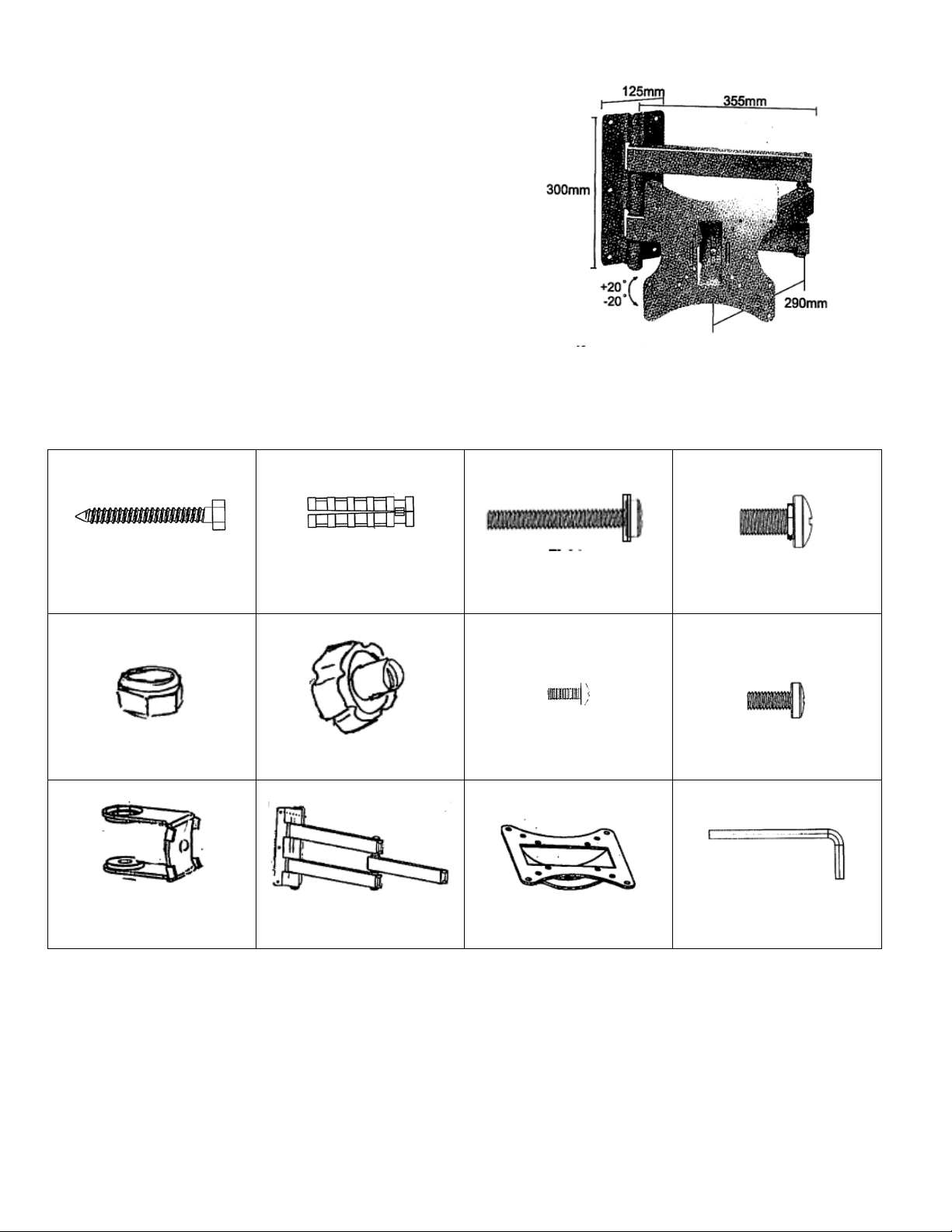
VESA 50/75/100/200x100/200x200mm
Max Weight: 66lbs/30kg
Package Contents:
Please review before starting to make sure no parts are missing. If any parts are missing, please
contact us to have replacement parts sent to you.
6x60mm
Lag Bolt x 6
Concrete Anchor
X 6
LG Retention Bolt
X 1
Sm Retention Bolt
X 1
X 4
X 1
Retention Nut
X 1
“C” Bracket
X 1
Retention Knob
Arm Assembl y
M4x10mm
X 4
Display Mounting Plate
X 1
M5x10mm
Allen Key
Introduction:
Thanks for purchasing the Monoprice MCD-WA5 adjustable flat panel display wall mount. The MCDWA5 is designed to be attractive, durable, easy to install and provide you with years of reliable
service. The mount is designed to be installed on to solid concrete or wooden board walls. Please
review this manual before you begin installation. If you are unsure about anything and do not feel
comfortable doing the installation yourself, please consul t t he advi c e o f a professional installer.
Page 2
Installation:
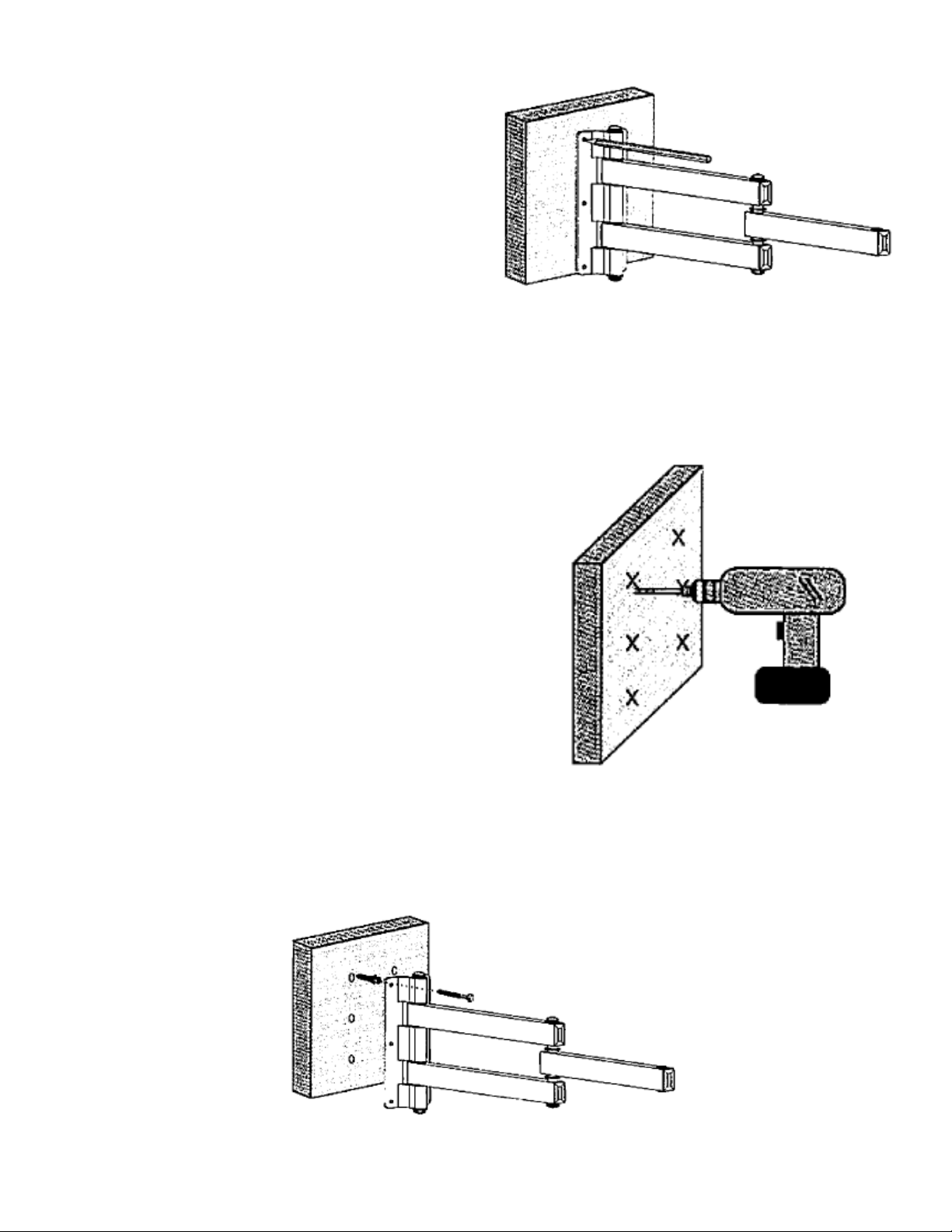
Figure 1
Figure 2
Figure 3
Step One:
Mark Your Wall - Use a level to positions the wall
plate of the arm assembly (part J) at the place on
the wall you want to install the mount and make sure
the plate is vertically straight. Holding the wall plate
to the wall, use a pencil to mark the 6 points the
mount will attached to the wall.
If you are installing on to a wood studded wall, you will need to use a stud finder to locate a stud in
the wall. Mark your stud. Use a level to position one side of the wall plate of the arm assembly (part
J) along the stud so that one column of holes is centered on the stud and make sure the plate is
vertically straight. Holding the wall plate to the wall, use a pencil to mark the 3 points the mount will
attach to the stud and the 3 points that will attach to plain drywall.
Step Two:
Drill Pilot Holes - If you are installing on to concrete or
solid brick, you will need to use the included concrete
anchors (part B). Drill 10 mm pilot holes approximately
60mm deep. Insert the anchors into each of the holes.
If you are installing onto a wood board wall, you will not
need any anchors as long as the wood board is
substantially thick. Drill 3 mm pilot holes approximately
60mm deep.
If you are installing onto drywall with wood studs, drill 3 mm
pilot holes approximately 60mm deep into the stud. For
the other side, you will need drywall anchors and bolts from
a local hardware store.
Step Three:
Attach The Arm Assembly To The W all - Hold up the arm assembly to the wall. Line up the holes on
the wall plate to the pilot holes and fasten the plate to the wall with the lag bolts (part A).
Page 3

Step Four:
Figure 4
Figure 5
Figure 6
Assemble The Display Mounting Plate Assembly - Connect
the display plate (part K) to the “C” bracket (part I) and insert
the small retaining bolt (part D) through the front of the
mounting plate, into the hole in the “C” bracket and secure it
with the retaining knob (part F).
Step Five:
After having prepped your flat panel display by
removing any table top stands as instructed in the
manual for your display, attach the display mounting
plate assembly from step four to the back of your
display. Make sure it is in the correct orientation. The
square shaped hole on the “C” bracket should be on the
top. Use four of the machine screws included with the
mount (Part G or H) or included with your display to
attach the plate to the back of the display. If none of
the included screws fit, contact the manufacturer of
your display to find out the appropriate size needed and
purchase them at a local hardware store.
Step Six:
Have some one assist you by lifting the display with the attached display plate assembly up to the
extension arm on the wall plate assembly from step one. Attach the “C” bracket to the end of the arm
and fasten it with the large retention bold (part C). Lock the bolt in place with the nut (part E). If the
extension are is too still or too loose, you can adjust the tension by turning the allen bolt at the joint of
the arm using the included all en key.
Congratulations, you’re done!
 Loading...