

Page 1
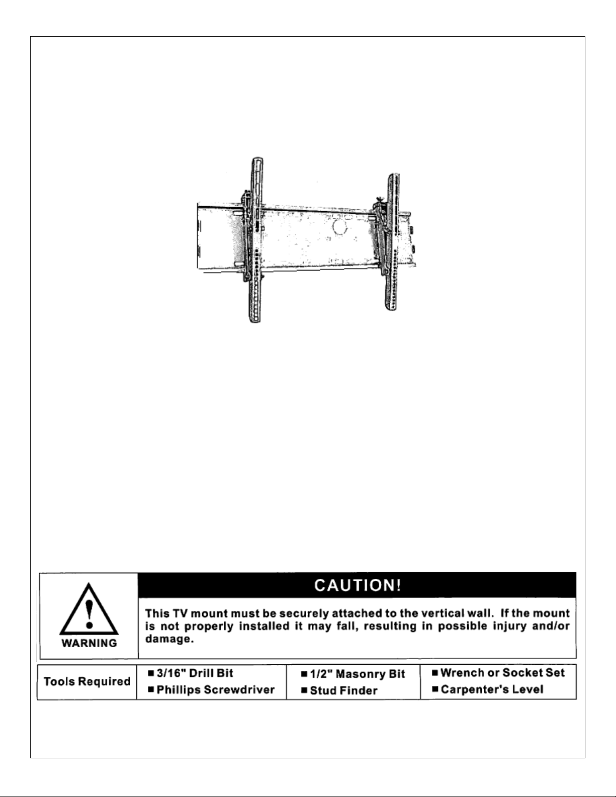
Monoprice Adjustable Tilt/Swivel Flat Panel Wall Mount
Model MLB-14/MLB-14L/MLB-14XL/MLB-14T
(PID# 2852/3004/3401/3900/4115/4174)
VESA Compliant: Up to 750x450 for MLB-14 & MLB-14T, 850x450 for MLB-14L and 1050x450 for MLB-14XL
Max Weight: 165lbs
Installation Instruction
UNPACKING INSTRUCTIONS
• Carefully open the carton, remove the contents and lay them out on cardboard or other protective surface to avoid
damage.
• Check the contents against the supplied parts list on the next page to assure that all components were received
undamaged. Do not use any damaged or defective parts.
IMPORTANT SAFETY INFORMATION
Install and use this device with care. Please read this entire manual before attempting installation and carefully follow all
instructions contained herein. Use proper safety equipment during installation.
Please call a qualified installation contractor for help if you:
• Don’t understand the instructions in this manual or have any doubts about the safety of the installation.
• You are uncertain about the nature of your wall.
Do not use this product for any purpose or in any configuration not explicitly specified in these instructions. Monoprice
hereby disclaims any and all liability for injury or damage arising from incorrect assembly, incorrect mounting or any
incorrect use of this product.
Note: The mounting components and hardware supplied in this package are not designed for installation to wall with
steel studs or to cinder block walls. If the hardware you need for your installation is not included, please consult your local
hardware store for proper mounting hardware for this application.
Page 2
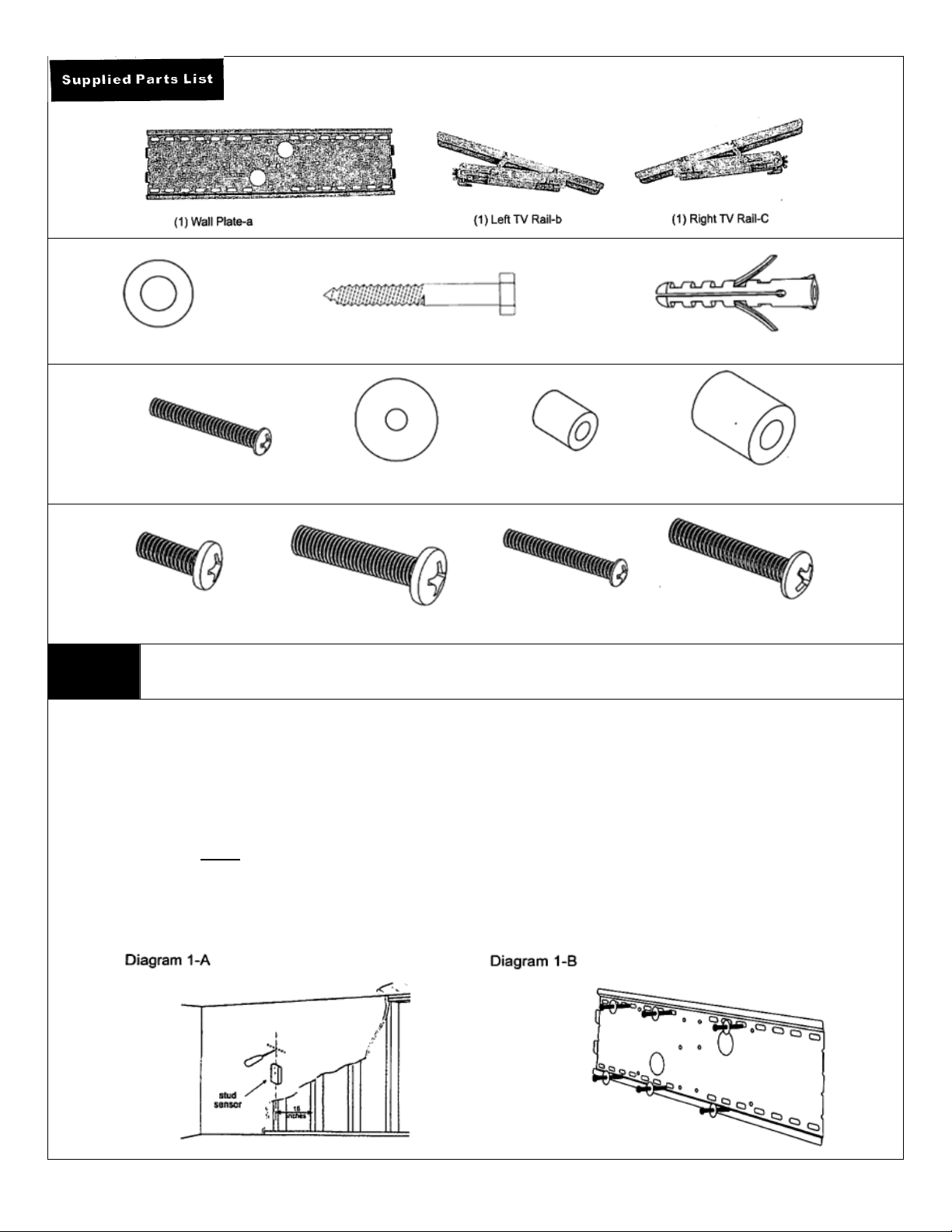
(10) Lag Bolt Washer – d (6) ¼”x2.5” Lag Bolt – e (6) Concrete Anchor - f
(4) M4x30mm Machine Screw – i (12) M4/M5 Washer – k (4) ½” Plastic Spacer – l (4) ¾” Plastic Spacer - j
(4) M8x25mm Screw–m (4) M8x40mm Screw–n (4) M5x30mm Screw–o (4) M6x30mm Screw-p
Step 1 Mounting the Wall Plate to the Wall
Brick, Solid Concrete and Concrete Block Mounting:
Use the Wall Plate (part a) as a template to mark 6 hole locations on the wall. Three in the top row of slots an d three more in the
bottom row. Make sure these holes are level and there is at l east 8” distance between any two holes. Pre-Drill these holes with a
10mm masonry bit to at least 60mm in depth. Insert a Concrete Anchor (part f) into each of these holes. Make sure the anchor is
seated completely flush with the concrete surface even if there is a l ayer of drywall or the other m aterial in front. Attach the Wall Pl ate
to the wall using 6 Lag Bolts (part e) and 6 Lag Bolt Washers (part d), as shown in Diagram 1-B.
Wood Stud mounting:
The Wall Plate (part a)
where the studs are located with an awl or thin nail as shown in Diagram 1-A. Pre-drill a 3mm deep hole at the desired height in each
stud using a 4mm drill bit. Make sure these holes are in the center of the studs and level with eac h other. Use the Wall Plate as a
template to mark the location of the second hole in each stud. Drill pilot holes at each of the marked locations. Attach the Wall Plate to
the wall using the 4 Lag Bolts (part e) and 4 Lag Bolt Washers (part d).
MUST be mounted to two wood studs. Use a stud finder to locate two adjacent studs. It is a good idea to verify
Page 3

Step 2 Mounting the TV Rails to the back of your Flat Panel TV
Make sure the TV Rails (parts b & c) are mounted at an equal dist ance from the top of the T V and as close to the ce nter as possible as
shown in diagram 2-A. The safety latches on the bottom of the arms should face outward from the television and the wing nuts should
point toward the top.. M4, M5 and M8 bolts are included. If other sizes are require d, they are available at your local hardwa re store.
Plastic Spacers (part l) are provided for use with M4 and M5 screws. Use these spacers for televisions with curved or recessed back
panels as shown in diagram 2-B. For flat back panels, no spacers are necessar y as s hown in diagram 2-C. Make su re you are using
the correct bolt size for your television. Some televisions have shallow threaded inserts. 4 extra spacers have been included to
offset shallow mounting holes if the bolts provided are too long. Never force a bolt in deeper than the mounting holes allow. Doing
so may damage your television. At the same time, make sure that the bolt tip is sunk deep enough into each hole to support the
television. Before hanging the television, tighten the wing nuts on both TV rails so that the mechanism does not move during
installation.
Step 3 Hang the TV onto the Wall Plate
Warning: Some TVs may require two people to lift! Monoprice is not responsible for personal injury or product damage.
First hook the Monitor Bracket (parts b & c) over the top of the wall plate (part a). Then, let the bottom of the monitor brackets rotated
to the bottom of the wall plate as shown in Diagram 3-A. Slide up the safety latches on the bottom of each r ail so that it engages the
bottom lip of the wall plate and tighten the safety screws to lock the latch in place. Finally, loose n the wing nuts on the top of each rail
to freely adjust the tilt angle of your television. Once the desired position is determined, tighten the wing nut to hold the television in
position as shown in diagram 3-B.
Congratulations! You’re Finished.
Thanks for Choosing a Monoprice Wall Mount. Enjoy!
 Loading...