

Page 1

Commercial Audio 60-Watt 2-Channel
70V/100V Mixer Amplifier
P/N 18800
User’s Manual
Page 2

CONTENTS
SAFETY WARNINGS AND GUIDELINES ............................................................................................................................... 3
INTRODUCTION ........................................................................................................................................................................................ 5
FEATURES ...................................................................................................................................................................................................... 5
CUSTOMER SERVICE ............................................................................................................................................................................ 5
PACKAGE CONTENTS ......................................................................................................................................................................... 6
PRODUCT OVERVIEW ......................................................................................................................................................................... 6
Front Panel ............................................................................................................................................................................................. 6
Rear Panel ............................................................................................................................................................................................... 7
CONSTANT VOLTAGE VS 8-OHM SPEAKER SYSTEMS .......................................................................................... 7
SAMPLE CONNECTION DIAGRAM .......................................................................................................................................... 9
CONSTANT RESISTANCE INSTALLATION .......................................................................................................................... 9
CONSTANT VOLTAGE INSTALLATION ................................................................................................................................ 11
BLOCK DIAGRAM ................................................................................................................................................................................. 13
SPECIFICATIONS .................................................................................................................................................................................... 14
TECHNICAL SUPPORT ....................................................................................................................................................................... 15
REGULATORY COMPLIANCE ...................................................................................................................................................... 15
Notice for FCC .................................................................................................................................................................................. 15
Notice for Industry Canada ................................................................................................................................................... 16
2
Page 3

SAFETY WARNINGS AND GUIDELINES
Please read this entire manual before using this device, paying extra attention to these
safety warnings and guidelines. Please keep this manual in a safe place for future
reference.
This device is intended for indoor use only.
Do not expose this device to water or moisture of any kind. Do not place drinks
or other containers with moisture on or near the device. If moisture does get in
or on the device, immediately unplug it from the power outlet and allow it to
fully dry before reapplying power.
Do not touch the device, the power cord, or any other connected cables with
wet hands.
Do not expose this device to excessively high temperatures. Do not place it in,
on, or near heat sources, such as a fireplace, stove, radiator, etc. Do not leave it
in direct sunlight.
This device ventilates excessive heat through the slots and openings in the case.
Do not block or cover these openings. Ensure that the device is in an open area
where it can get sufficient airflow to keep from overheating.
Do not expose this device to excessive vibration.
Do not place or install this device in an area where it can be exposed to
excessive amounts of dust, humidity, oil, smoke, or combustible vapors.
Use only in a well-ventilated area. Do not use in close, confined spaces.
Prior to operation, check the unit and power cord for physical damage. Do not
use if physical damage has occurred.
Before plugging the unit into a power outlet, ensure that the outlet provides the
same type and level of power required by the device.
This device uses a grounded power cord and requires a ground connection for
safe operation. Ensure that the power source has a proper ground connection.
Do not modify the plug or use a "cheater" plug to bypass the ground connection.
Unplug this device from the power source when not in use.
3
Page 4

Take care to prevent damage to the power cord. Do not allow it to become
crimped, pinched, walked on, or become tangled with other cords. Ensure that
the power cord does not present a tripping hazard.
Never unplug the unit by pulling on the power cord. Always grasp the connector
head.
Ensure that power is turned off and disconnected before making any electrical
connections.
Clean using a soft, dry cloth only. Do not use chemical cleaners, solvents, or
detergents. For stubborn deposits, moisten the cloth with warm water.
This device has no user serviceable parts. Do not attempt to open, service, or
modify this device.
Ensure that the terminal cover is installed over the speaker terminals before
applying power. These terminals carry high voltage and can cause severe electric
shock if touched during operation.
Always set the Master Volume knob to the minimum position before applying
power to the amplifier. Transient voltage spikes during power on can cause loud
popping in the speakers, which can damage the speakers.
Do not operate this amplifier for extended periods of time with audio distortion
present. Audio distortion can cause excessive heat and can damage the amplifier
and/or speakers.
If using this amplifier to drive a 70V or 100V speaker array, ensure that the total
wattage rating of the speaker array does not exceed 80% of the amplifier's rated
RMS power level, i.e., 48 watts.
4
Page 5

INTRODUCTION
Thank you for purchasing this Commercial Audio 60-Watt 70V/100V Mixer Amplifier!
This amplifier is designed to drive a conventional 4-ohm or 8-ohm speaker system as
well as 70-volt and 100-volt constant voltage speaker systems. It features three
unbalanced 1/4" microphone inputs, two of which can be switched to unbalanced RCA
and 1/4" auxiliary jacks instead of microphone level inputs.
FEATURES
Three 1/4" microphone inputs
One RCA and one 1/4" auxiliary inputs
Three separate mixing/volume controls for MIC 1, MIC 2/AUX 1, and MIC 3/AUX 2
Treble and bass controls
MIC 1 input has priority
4-ohm and 8-ohm constant resistance output options
70-volt and 100-volt constant voltage output options
100 ~ 240 VAC, 50/60 Hz input voltage range
CUSTOMER SERVICE
The Monoprice Customer Service department is dedicated to ensuring that your
ordering, purchasing, and delivery experience is second to none. If you have any
problem with your order, please give us an opportunity to make it right. You can
contact a Monoprice Customer Service representative through the Live Chat link on our
website www.monoprice.com during normal business hours (Mon-Fri: 5am-7pm PT, Sat-
Sun: 9am-6pm PT) or via email at support@monoprice.com
5
Page 6

PACKAGE CONTENTS
Please take an inventory of the package contents to ensure you have all the items listed
below. If anything is missing or damaged, please contact Monoprice Customer Service
for a replacement.
1x Commercial Audio 60-Watt 2-Channel 70V/100V Mixer Amplifier
1x User's Manual
PRODUCT OVERVIEW
Front Panel
1. MIC 1 Mixing/Volume Control
2. MIC 2/AUX 1 Mixing/Volume Control
3. MIC 3/AUX 2 Mixing/Volume Control
4. Bass Level Control
5. Treble Level Control
6. Master Volume Control
7. Power LED Indicator
8. Power Switch
6
Page 7
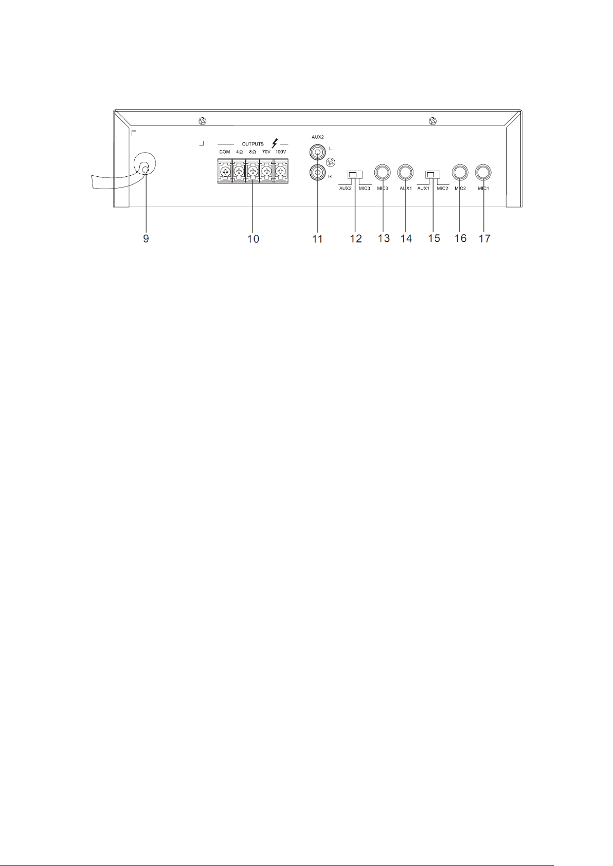
Rear Panel
9. AC Power Cord
10. Speaker Terminals
11. AUX 2 Unbalanced RCA Input
12. AUX 2/MIC 3 Selector Switch
13. MIC 3 Unbalanced 1/4" Input
14. AUX 1 Unbalanced 1/4" Input
15. AUX 1/MIC 2 Selector Switch
16. MIC 2 Unbalanced 1/4" Input
17. MIC 1 Unbalanced 1/4" Input
CONSTANT VOLTAGE VS 8-OHM SPEAKER SYSTEMS
A constant voltage speaker system differs from a traditional 8-ohm speaker system in
that it uses a step-up transformer at the audio source to raise the voltage and lower the
current on the transmission line. At the speaker end, a step-down transformer converts
the signal back to a normal speaker level voltage. This reduces power loss during
transmission, which allows for the use of longer speaker wire runs using smaller gauge
wire.
Additionally, a constant voltage speaker system allows for the use of multiple speakers
on each channel, without the need for complicated impedance calculations and
configurations. In a constant voltage system, all speakers on a given channel are
connected in parallel and the complicated impedance calculations are replaced by
simple wattage calculations.
7
Page 8

For example, if you want to connect two speakers per channel in a traditional 8-ohm
speaker system, you must either connect them in series, which results in an overall 16-
ohm impedance, or in parallel, which results in an overall 4-ohm impedance. In the first
case, the 16-ohms impedance effectively halves the output power of your amplifier,
resulting in lower overall volume levels. In the latter case, the 4-ohms impedance means
that your amplifier will have to work harder and must be rated as stable at 4 ohms.
Adding a third speaker to the mix would complicate it further, producing either a 24-
ohm or 2.67-ohm overall impedance. Note that very few amplifiers are stable under 2-
ohm loads, so that is usually not an option.
On the other hand, with a constant voltage system, you consider first the RMS output
wattage of the amplifier. This should be reduced by 20% to compensate for insertion
loss. For example, if using a 100-watt amplifier, the total load from speakers should not
exceed 80 watts.
Each individual speaker on a given channel is set to a value such that the total does not
exceed the rated power, less 20%. You do not need to worry about making the total as
close as possible to the limit; just ensure that the total does not exceed the limit.
If all speakers are set to the same wattage value, they will all have the same volume
level. If one speaker is set to a higher wattage value, it will be louder than the others,
while a speaker set to a smaller value will be quieter than the others. This allows you to
compensate for the environment in which the speaker is placed. For example, a speaker
placed outside would need to be louder than a speaker placed in a small room.
8
Page 9

SAMPLE CONNECTION DIAGRAM
CONSTANT RESISTANCE INSTALLATION
Perform the following steps to install this amplifier in a 4-ohm or 8-ohm speaker
system.
1. Ensure that all equipment to be connected is powered off and unplugged from
its power source before making any electric/audio connections.
2. Place the amplifier in its intended location.
3. Using speaker wire (not included), create a speaker array with a 4-ohm or 8-ohm
overall load. This can be a single 4-ohm or 8-ohm speaker or a number of
speakers calculated to produce a 4-ohm or 8-ohm load.
For example, you could connect two 4-ohm speakers in series to create an 8-
ohm load. Alternatively, you can connect two 8-ohm speakers in series to create
9
Page 10

a 16-ohm array, then connect a second 16-ohm array in parallel to the first to
create an overall 8-ohm speaker load. Speaker load calculators are available on
the internet to help with the math.
4. Connect the negative lead of the speaker wire to the COM terminal on the
amplifier, then connect the positive lead to either the 4-ohm or 8-ohm terminal,
depending on the overall impedance of your speaker array.
5. (Optional) Plug a dynamic microphone into the MIC 1 Input (17).
6. (Optional) Either plug a dynamic microphone into the MIC 2 Input (16) or plug a
line-level device, such as the headphone output of an mp3 player or
smartphone, into the AUX 1 Input (14). If using the MIC 2 Input, set the AUX
1/MIC 2 Switch (15) to the MIC 2 position, otherwise if using the AUX 1 Input, set
it to the AUX 1 position.
7. (Optional) Either plug a dynamic microphone into the MIC 3 Input (13) or plug a
line-level device, such as a CD player, into the AUX 2 Input (11). If using the MIC 3
Input, set the AUX 2/MIC 3 Switch (12) to the MIC 3 position, otherwise if using
the AUX 2 input, set it to the AUX 2 position.
8. Ensure that the Master Volume Control (6) is turned fully counterclockwise to
the minimum position.
9. Set the MIC 1 Mixing/Volume Control (1), the AUX 1/MIC 2 Mixing/Volume
Control (2), and the AUX 2/MIC 3 Mixing/Volume Control (3) knobs to the
midpoint.
10. Ensure that the Power Switch (8) is in the OFF position.
11. Plug the AC Power Cord (9) into a nearby AC power outlet, then flip the Power
Switch (8) to the ON Position.
12. Plug in and power on all connected equipment. Start audio playback as desired
on the various inputs.
13. Slowly increase the Master Volume Control (6) to comfortable volume level.
Adjust the appropriate Mixing/Volume Controls (1, 2, and 3) to balance the
inputs as desired.
Congratulations, your new amplifier is properly installed and operating!
10
Page 11

CONSTANT VOLTAGE INSTALLATION
Perform the following steps to install this amplifier with a 70-volt or 100-volt constant
voltage speaker array.
1. Ensure that all equipment to be connected is powered off and unplugged from
its power source before making any electric/audio connections.
2. Place the amplifier in its intended location.
3. Using speaker wire (not included), create a speaker array using one or more 70-
volt or 100-volt speakers. All speakers should be connected in parallel.
4. Set the wattage switches on the speakers to a value that is equal to or less than
48 watts in total (80% of the 60-watt amplifier power rating). For example, if
you have 4 speakers, each one should be set to a value of 12 watts or less.
Note that you do not need to worry about making the total as close as possible
to the limit; just ensure that the total does not exceed the limit. Also note that
the speakers do not have to be set to the same wattage value, but those set to
higher wattage values will be louder than those set to lower values.
5. Connect the negative speaker wire lead to the COM terminal, then connect the
positive lead to either the 70V or 100V terminal, depending on the types of
speakers in the array.
6. (Optional) Plug a dynamic microphone into the MIC 1 Input (17).
11
Page 12

7. (Optional) Either plug a dynamic microphone into the MIC 2 Input (16) or plug a
line-level device, such as the headphone output of an mp3 player or
smartphone, into the AUX 1 Input (14). If using the MIC 2 Input, set the AUX
1/MIC 2 Switch (15) to the MIC 2 position, otherwise if using the AUX 1 Input, set
it to the AUX 1 position.
8. (Optional) Either plug a dynamic microphone into the MIC 3 Input (13) or plug a
line-level device, such as a CD player, into the AUX 2 Input (11). If using the MIC 3
Input, set the AUX 2/MIC 3 Switch (12) to the MIC 3 position, otherwise if using
the AUX 2 input, set it to the AUX 2 position.
9. Ensure that the Master Volume Control (6) is turned fully counterclockwise to
the minimum position.
10. Set the MIC 1 Mixing/Volume Control (1), the AUX 1/MIC 2 Mixing/Volume
Control (2), and the AUX 2/MIC 3 Mixing/Volume Control (3) knobs to the
midpoint.
11. Ensure that the Power Switch (8) is in the OFF position.
12. Plug the AC Power Cord (9) into a nearby AC power outlet, then flip the Power
Switch (8) to the ON Position.
13. Plug in and power on all connected equipment. Start audio playback as desired
on the various inputs.
14. Slowly increase the Master Volume Control (6) to comfortable volume level.
Adjust the appropriate Mixing/Volume Controls (1, 2, and 3) to balance the
inputs as desired.
Congratulations, your new amplifier is properly installed and operating!
12
Page 13

BLOCK DIAGRAM
13
Page 14

SPECIFICATIONS
Model
18800
Rated Power Output
60 watts
Speaker Outputs
4-ohm, 8-ohm, 70-volt, and 100-volt
Inputs
3x 1/4" unbalanced microphone
1x 1/4" unbalanced auxiliary
1x RCA unbalanced auxiliary
Microphone Input Sensitivity
5mV
Auxiliary Input Sensitivity
350mV
Frequency Response
80 Hz ~ 16 kHz (-3dB)
Signal-to-Noise Ratio
≥ 75dB
Total Harmonic Distortion
≤ 1%
Bass Tone Control
± 10dB at 100 Hz
Treble Tone Control
± 10dB at 10kHz
Priority Function
MIC 1 has priority
Protect Circuits
High temperature, overload, short circuit
Input Power
120 VAC, 50/60 Hz
Power Consumption
80 watts
Dimensions
11.2" x 7.4" x 2.6" (284 x 188 x 67 mm)
Weight
7.7 lbs. (3.5 kg)
14
Page 15

TECHNICAL SUPPORT
Monoprice is pleased to provide free, live, online technical support to assist you with
any questions you may have about installation, setup, troubleshooting, or product
recommendations. If you ever need assistance with your new product, please come
online to talk to one of our friendly and knowledgeable Tech Support Associates.
Technical support is available through the online chat button on our website
www.monoprice.com during regular business hours, 7 days a week. You can also get
assistance through email by sending a message to tech@monoprice.com
REGULATORY COMPLIANCE
Notice for FCC
This device complies with Part 15 of the FCC rules. Operation is subject to the following
two conditions: (1) this device may not cause harmful interference, and (2) this device
must accept any interference received, including interference that may cause undesired
operation.
Modifying the equipment without Monoprice’s authorization may result in the
equipment no longer complying with FCC requirements for Class B digital devices. In
that event, your right to use the equipment may be limited by FCC regulations, and you
may be required to correct any interference to radio or television communications at
your own expense.
This equipment has been tested and found to comply with the limits for a Class B digital
device, pursuant to Part 15 of the FCC Rules. These limits are designed to provide
reasonable protection against harmful interference in a residential installation. This
equipment generates, uses and can radiate radio frequency energy and, if not installed
and used in accordance with the instructions, may cause harmful interference to radio
communications. However, there is no guarantee that interference will not occur in a
particular installation. If this equipment does cause harmful interference to radio or
television reception, which can be determined by turning the equipment off and on,
the user is encouraged to try to correct the interference by one or more of the
following measures:
15
Page 16

Reorient or relocate the receiving antenna.
Increase the separation between the equipment and receiver.
Connect the equipment into an outlet on a circuit different from that to which
the receiver is connected.
Consult the dealer or an experienced radio/TV technician for help.
Notice for Industry Canada
This Class B digital apparatus complies with Canadian ICES-003.
Cet appareil numérique de la classe B est conforme à la norme NMB-003 du Canada.
16
 Loading...