

Monogram ZXADJB30PSS Installation manual
Installation ZXADJB30PSS, ZXADJB36PSS, ZXADJ48PSS
Instructions 30" to 36" Adjustable Backsplash
WARNING:
To prevent ignition of combustible materials,
the entire back wall above the range must
be protected by a backsplash constructed
of non-combustible material.
BEFORE YOU BEGIN
Read these instructions completely
and carefully.
IMPORTANT: Save these instructions for local
inspector’s use.
ORTANT
IMP
AND ORDINANCES.
NOTE TO INSTALLER: Be sure to leave these
uctions with the Consumer
instr
TE TO CONSUMER: Keep these instructions
NO
with your Owner’s Manual for future reference.
• This backsplash adjusts to fit the space between
the top of the range and the bottom of the hood,
om 30" Min. t
fr
• Maximum shelf load-bearing weight is 40 lbs.
: OBSERVE ALL GOVERNING CODES
.
o 36" Max. height
.
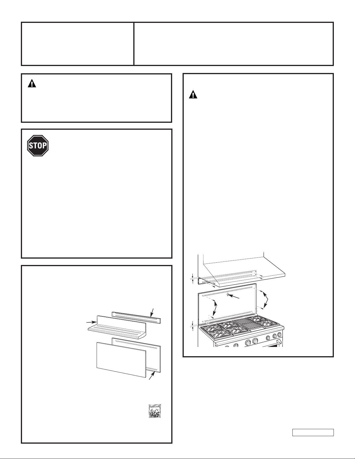
INSTALL THE WALL SUPPORT PANELS
W
ARNING:
must be securely fastened to the wall. Failure to
do so could result in damage or personal injury.
IMPORTANT: This backsplash is designed to cover the wall
between the bottom of the hood and the top of the range.
The vent hood should be installed over the rangetop or
range before installing this backsplash.
• Install and level the Range/Rangetop according
to the product installation instructions.
• Remove backsplash packaging and protective film.
• Locate wall studs on each side. Where studs are not
available, plan to use wall anchors (not provided).
• Use a level to pencil 2 horizontal lines on the wall,
one 1/8" below the vent hood and the other 1/8" above
the Range/Rangetop. This 1/8" space allows the cover
panels to overlap the wall supports.
• Secure the top wall support panel to the wall with 4 wood
screws, through the outermost studs.
• Use 4 wood screws to secure the bottom wall support
panel. The center slot should be positioned at the top.
The gap between the top and bottom support panels
will be covered by the top cover with shelf.
The wall support panels
TOOLS AND MATERIALS REQUIRED
Gloves to protect against sharp edges
•
T-15 and #2 Phillips scr
•
• Drill with 3/32" and 9/64" bits
• Safety glasses
• Level
• Pencil
Top Cover
with Shelf
This Kit Includes
• Top wall support
• Bottom wall support
op cover with shelf
T
•
• Bottom cover
• Hardware package with
– 9 Stainless Steel Torx 15 #8
self-tapping screws
– 9 Phillips #2 pan head wood #10 screws
– 3 Stainless Steel #2 truss head
#10 screws (for alternate
installation method)
ewdrivers
Top Wall
Suppor
Bottom Cover
Bottom Wall Support
t
Hardware
Package
Secure the top
panel to the wall
1/8″
Center
Arrow
Wood Screws
1/8″
W
Screws
1
with 4 wood
screws
ood
Secure
the bottom panel
to the wall with
4 wood screws
31-10692
04-08 JR
ZXADJB30PSS, ZXADJB36PSS, ZXADJB48PSS Accessory Installation
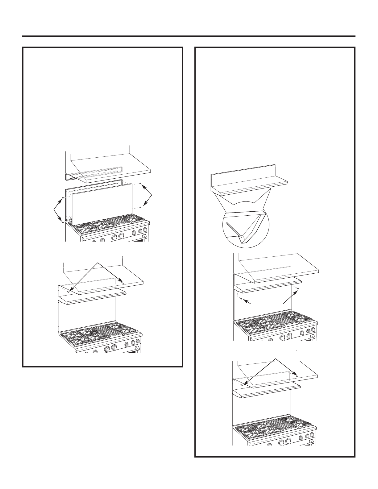
INSTALL COVER PANELS
See alternate method if side access is blocked.
• Hold the bottom cover over the bottom support
while driving one screw (provided) into each side.
• Place the top cover with shelf over the top wall
support. If you have access to the sides, secure
the panel with two screws on each side.
• Secure the top cover with shelf to the top
support with screws through the front of the panel,
at the top corners. Use one screw on each side.
Install
Cover Panel
Install
Screw
Screw
INSTALL COVER PANELS (cont.)
ALTERNATE METHOD: When side access is blocked
• Install bottom cover over the bottom support while
driving one screw into each side.
• Hold top cover in place while marking screw
locations, just below shelf support and onto bottom
cover.
• Remove the shelf and drill a 9/64" diameter
hole in the pencil-marked locations.
• Mount the top cover over the top support
and secure the front cover with screws through
the drilled holes on each side.
• Install screws through each top corner.
Mark Scr
for Alternate Method
ew Locations
Install Corner Screws
Install Screw
on Each Side
Install Screw in Top Corner on Each Side
Shelf
2
Consignes ZXADJB30PSS, ZXADJB36PSS, ZXADJ48PSS
d’installation Dosseret ajustable 30" à 36"
AVERTISSEMENT:
Afin d’éviter que les matériaux inflammables ne prennent
feu, la totalité de la surface du mur se trouvant au-dessus
de la cuisinière doit être protégée par un dosseret ignifuge.
AVANT DE COMMENCER
Lisez attentivement l’ensemble des
consignes.
IMPORTANT: Conservez ces consignes, elles peuvent
vous être utiles pour toute inspection de votre
installation.
IMPORTANT: RESPECTEZ TOUTES LES NORMES AINSI
QUE LES RECOMMANDATIONS PRÉCONISÉES PAR
LES AUTORITÉS COMPÉTENTES.
REMARQUE À L'ATTENTION DE L'INSTALLATEUR:
Après intervention, assurez-vous d’avoir remis ces
instructions à l’utilisateur.
REMARQUE À L'ATTENTION DE L’UTILISATEUR:
Conservez ces instructions avec le manuel de
l’utilisateur pour toute consultation ultérieure.
• Ce dosseret est conçu combler l’espace entre
le haut de la cuisinière et le bas de la hotte, entre
une hauteur maximale de 76 cm et 91 cm.
• Le poids maximal de portance de l’étagère
est de 18 kg.
OUTILS ET MATÉRIEL NÉCESSAIRES
• Gants pour vous protéger des parties tranchantes
ournevis cruciforme 2 et T-15
T
•
• Percez avec des forets 23 mm
(3/32") et 35 mm (9/64")
unettes pr
L
•
eau
Niv
•
• Crayon
otectrices
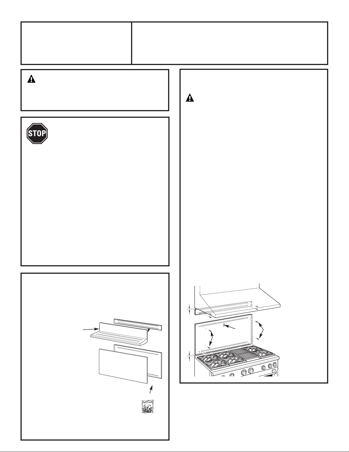
Plaque
supérieure
avec étagère
Ce Kit comprend
• Panneau de support mural
• Panneau mur inférieur
Top cover with shelf
•
• Plaque inférieure
• Sachet de matériel contenant
– 9 tornillos auto-r
Torx 15 de acero inoxidable
– 9 tornillos de estr
madera de cabeza troncocónica #10
– 3 tornillos de cabeza segmentada
#10 de acero inoxidable #2 (para
un método de instalación alternativo)
oscantes #8
ella #2 para
Plaque inférieure
Support mural
supérieur
t mural
Suppor
inférieur
e
Sachet
de matériel
INSTALLEZ LES PANNEAUX
DE SUPPORT MURAL
AVERTISSEMENT
de support mural doivent être correctement fixés
au mur afin d'éviter toute blessure ou dommage
matériel.
IMPORTANT: Ce dosseret est conçu pour couvrir le mur
entre la partie supérieure de la cuisinière et la partie
inférieure de la hotte. La hotte d’extraction doit être installée
sur la table de cuisson ou de la cuisinière avant d’installer
le dosseret.
• Installez et ajustez la position de la table
de cuisson/cuisinière conformément aux consignes
d’installation.
• Retirez l’emballage du dosseret et le film protecteur.
• Localisez les poteaux muraux sur chaque côté.
En l’absence de poteaux, utilisez plutôt des chevilles
murales (non fournies).
• Utilisez un niveau pour tracer au crayon 2 lignes
horizontales sur le mur, une à 1/8" sous la hotte
d’extraction et l’autre à 1/8" au-dessus de la table de
caisson/cuisinière. Cet espace de 1/8" fait que le panneau
de recouvrement se superpose aux supports muraux.
• Fixez le panneau mural supérieur au mur à l’aide de 4
vis à bois, à travers les poteaux externes.
• Utilisez 4 vis à bois pour fixer support mural inférieur.
La rainure centrale doit être placée en haut.
L’espace séparant le panneau de support du bas de celui
du haut sera comblé par la plaque supérieur avec étagère.
31 mm
Flèche
centrale
vis à bois
31 mm
3
:
Les panneaux
Fixez le panneau
supérieur au mur
avec 4 vis à bois
vis à
bois
Fixez le panneau
inférieur au mur
avec 4 vis à bois
 Loading...