

Monogram ZVB36, ZVB30, JXBC57 Installation Instructions Manual

Installation
Instructions
If you have questions, call 800-GE-CARES or visit our website at: www.monogram.com
Downdraft Vent Systems
36" Wide Models:
ZVB36
30" Wide Models:
ZVB30
Monogram.
®
We bring good things to life.
CAUTION
WARNING
Before you begin—Read these instructions completely and carefully.
IMPORTANT: Save these instructions for local inspector’s use.
IMPORTANT: OBSERVE ALL GOVERNING CODES AND ORDINANCES.
Note to Installer: Be sure to leave these instructions with the Consumer.
Note to Consumer: Keep these instructions with your Owner’s Manual for future reference.
This appliance must be properly grounded. See “Power Supply”, page 10.
If you received a damaged vent, you should
immediately contact your dealer or builder.
Proper installation is the responsibility of the
installer. Product failure due to improper
installation is not covered under the GE
Appliance Warranty. See the Owner’s Manual
for warranty information.
For Monogram local service in your area,
1-800-444-1845.
For Monogram service in Canada,
1-888-880-3030.
For Monogram Parts and Accessories, call
1-800-626-2002.
www.monogram.com
WARNING:
To reduce the risk of fire, electric shock, or
injury to persons, observe the following.
A. Use this unit only in the manner intended
by the manufacturer. If you have questions,
contact the manufacturer.
B. Before service or cleaning unit, switch
power off at service panel and lock the
service disconnecting means to prevent
power from being switched on accidentally.
When the service disconnecting means
cannot be locked, securely fasten a prominent warning device, such as a tag, to the
service panel.
• Do not attempt to repair or replace any part
of the downdraft system unless it is specifically recommended in this book. All other
servicing should be performed by a qualified technician.
• For general ventilating use only. Do not use
the exhaust hazardous or explosive materials
and vapors.
• Installation work and electrical wiring must
be done by a qualifed person(s). In accordance with all applicable codes and standards including fire-rated construction.
To reduce the risk of fire and to properly
exhaust air, be sure to duct air outdoors. Do
not vent exhaust air into spaces within walls or
ceilings or into attics, crawl spaces or garages.
WARNING: TO REDUCE THE RISK OF
FIRE, USE ONLY METAL DUCTWORK.
Do not attempt to repair or replace any part
of the downdraft system unless it is specifically
recommended in this book. All other servicing should be performed by a qualified
technician.
Contents
2
Design Information
Models Available ........................................................... 3
Accessories ..................................................................... 3
Product Dimensions ..................................................... 3
Advance Planning ..................................................... 4, 5
Installation Preparation
Cutouts for Monogram Cooktops ...................... 6, 7, 8
Clearances...................................................................... 9
Tools and Materials Required...................................... 9
Parts Supplied ............................................................... 9
Remove Packaging ...................................................... 10
Power Supply ............................................................... 10
Venting Options .................................................... 11, 12
Ductwork
Duct Fittings ................................................................ 13
Installation
Step 1, Install Downdraft Vent ................................... 14
Step 2, Install the Ductwork ....................................... 14
Step 3, Install Raise/Lower Switch ............................ 15
Step 4, Connect Power ............................................... 16
Step 5, Install Filters, Check Operation.................... 16
Cleaning ....................................................................... 16
Accessories
JXRB57 Kit for Indoor Remote Blower Locations ... 17
JXBC57 Kit for Outdoor Remote Blower Locations 20
Design Information
2-1/4"
3-1/4"
7"
12-3/8"
5-3/8"
3-1/4"
7-1/2"
6-3/8"
2"
8-1/2" Lift
Downdraft Vent Systems
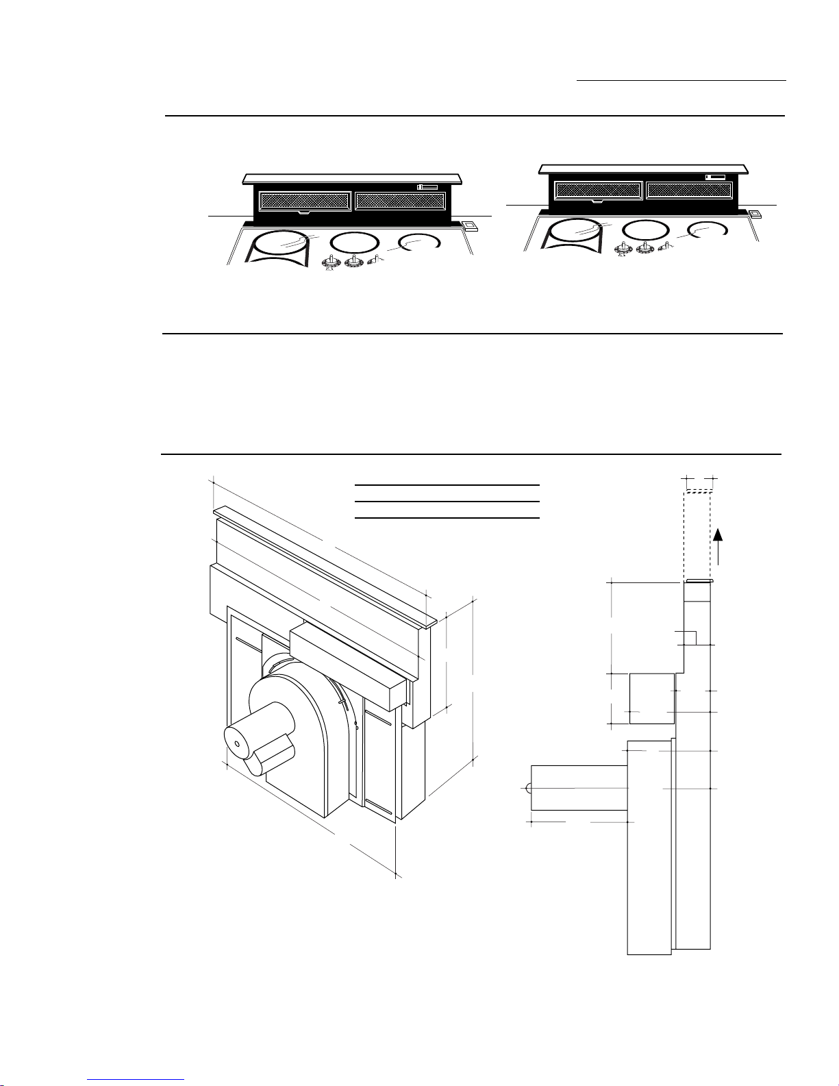
Models
Available
Accessories
Product
Dimensions
These downdraft vents systems can be
retracted when not in use.
1
1
8
8
7
6
5
8
7
8
2
2
7
7
3
3
6
6
4
4
5
5
UNIT ON
1
8
2
7
ZVB36
1
2
3
4
1
2
36" Wide Downdraft Vent
in white, black and stainless steel
• JXRB57 optional accessory for indoor
remote location of the blower/motor
assembly. Use this kit when the blower and
motor assembly will be located outside or
below the cabinet floor.
30" Models 30" 28-3/8"
36" Models 36" 33-3/4"
A
ZVB30
30" Wide Downdraft Vent
in white, black and stainless steel
• JXBC57 optional outdoor cover accessory
for remote installation of blower and motor
assembly on an outside wall.
AB
1
1
2
3
1
2
3
4
1
8
8
7
6
4
5
8
7
6
5
8
2
2
7
7
3
3
6
6
4
4
5
5
UNIT ON
1
8
2
7
3
6
4
5
B
14-3/4"
27"
26"
3
Design Information
Base
Cabinet
Filler Panel
Base Sink
BS30 Min. For ZVB30
BS36 Min. For ZVB36
Filler Panel
Maintain Cutout Clearances
to Front Edge as Specified
Downdraft Vent Systems
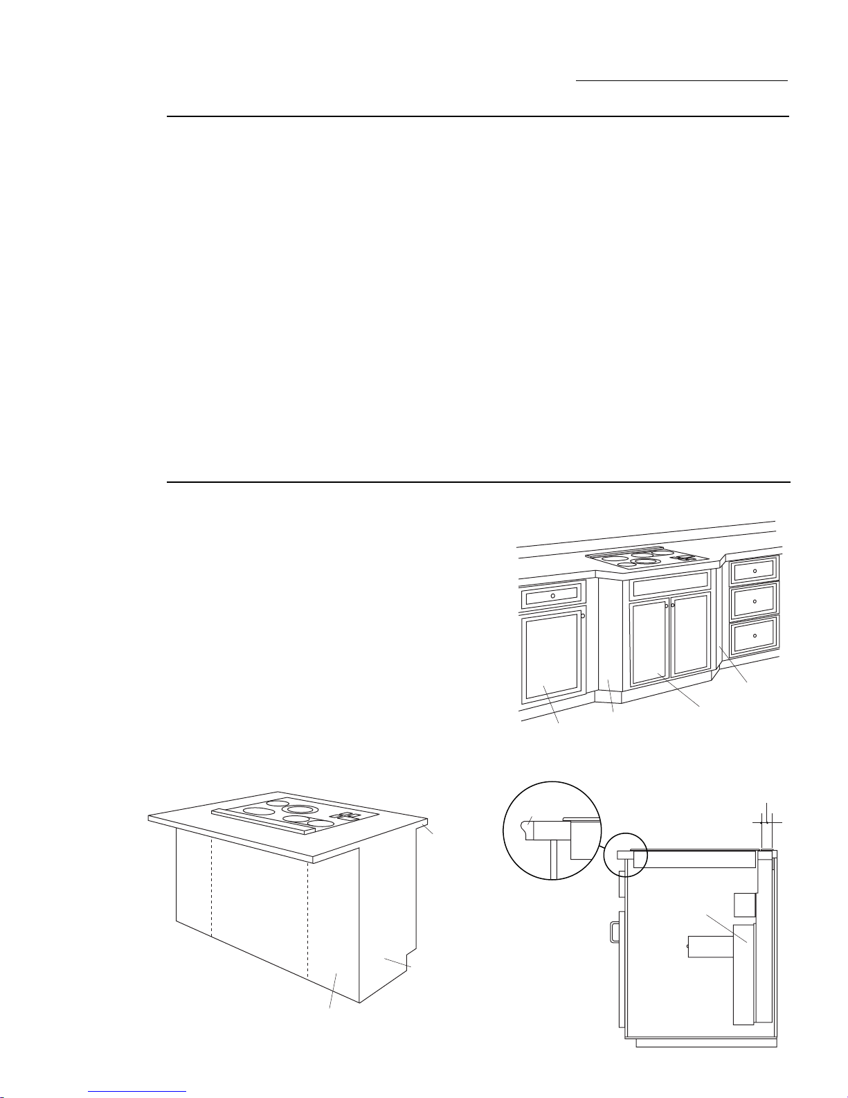
Advance
Planning
The installation of these downdraft vents with
any Monogram cooktop requires careful
consideration. For accurate planning, this
book provides individual dimension drawings
for the vent and the Monogram cooktop
installation.
Countertop Requirements:
The countertop must have a deep flat surface
to accommodate the cooktop and the vent.
Countertops with a rolled front edge and
backsplash may not provide the flat surface
area required.
Base Cabinet Requirements:
The base cabinet must be deep enough to
accommodate the min. clearance to the front
edge of the countertop, the cooktop burner
box and the vent.
Creative Solutions
√ When the kitchen design calls for an against the wall
installation, move the base cabinet forward, 3” to 5”.
Filler panels or complimentary moldings can be
added to the exposed cabinet sides.
Before you begin you must:
1. Review countertop dimension illustrations
to be sure you will have enough flat
countertop surface.
2. Check to be sure that the total countertop
depth required (including min. cutout to
front edge depth) allows enough space for a
backsplash.
3. Review the cabinet illustration. Check to be
sure that the interior cabinet depth will
house the cooktop burner box, the vent and
the cutout clearance from the front.
4. When countertop and cabinet depth
present a problem, review Creative Solutions.
5. Read this book completely to accurately
plan the installation location, clearances and
ductwork requirements.
With careful planning you can achieve a
custom look with minimal adjustments.
√ In an island or pennisula, use an extra deep
countertop. The countertop overhang at the front can
be adjusted to meet setback to cutout requirements.
√ When the cutout to front edge of the countertop
requirement is more than 2”, add a bullnose trim to
the front edge of the countertop. Include the trim
thickness when measuring front edge to cutout
requirement. By adding the trim, the cooktop can be
moved forward, providing additional countertop depth
and interior cabinet space.
B18
Base Sink
BS30 to BS42
B18
End
Panel
Countertop
Overhang
per Cooktop
Clearances
Must be
Maintained
Trim
Add a Bullnose Trim
or Other Decorative
Molding to Increase
Countertop Depth
and to Maintain
Required Clearance
From Front Edge to
Cutout.
1-7/8"
DOWNDRAFT
VENT
4
Cover Panel

Design Information
Downdraft Vent Systems
Advance
Planning
(continued)
Clearances
• The downdraft system with blower, motor
and ductwork will occupy the cabinet below
the countertop and cooktop.
• The blower/motor assembly can be located
below the cabinet floor. The assembly will fit
between 16" floor joists. Order JXRB57 for
indoor remote locations.
– In this installation a transition to 6" round
is required.
• The blower motor assembly can also be
installed outdoors. Order JXBC57 for
remote blower installations outdoors.
– In this installation one or two 3-1/4"x10"
to 6" round transitions may be required.
• Refer to “Cooktop Clearances” for information on appropriate placement and necessary clearances when planning installation.
• Refer to your specific cooktop installation
instruction for other appropriate clearances.
• Avoid placing cabinetry directly above the
cooking surface when possible.
Ductwork
Prepare ductwork to vent to the outdoors.
• Use the shortest and straightest duct run
possible.
– The maximum permissible length for duct
run is 150 feet.
– Refer to “Duct Fittings” chart to calculate
equivalent length for various duct
configurations.
• If cabinetry is used above the cooking
surface:
– Use cabinets no more than 13" deep.
– Maintain 30" minimum clearance between
cooktop and unprotected cabinets directly
above cooktop.
– If clearance is less than 30", protect
cabinet bottoms with flame-retardant
millboard at least 1/4" thick or gypsum
board at least 3/16" thick covered with 28
gauge sheet steel or .02" thick copper.
– Clearance between cooktop and protected
cabinetry must not be less than 24."
EXCEPTION: Installation of a listed microwave oven or cooking appliance over the
cooktop shall conform to the installation
instructions packed with that appliance.
– Working areas adjacent to the cooktop
should have 18" minimum clearance
between countertop and cabinet bottom.
• Installation must conform with local codes.
• The downdraft blower system is designed to
use 3-1/4" x 10" ductwork. It can be
transitioned to 6" round.
• Ductwork MUST be vented to the outside–
never into a crawl space, attic or other
enclosed space.
• Determine the need for a wall cap or roof
cap. Order the cap in advance.
Electrical and Gas Locations
Plan the placement of the electrical outlet and
gas (if used) carefully. Gas or electrical outlets
cannot be placed on the back wall of the
cabinet because it may interfere with the
downdraft plenum.
• Install a standard electrical outlet within
reach of the vents’ two foot long power
cord.
– The vent and a Monogram gas cooktop
combination can operate from the same
120 volt standard duplex outlet.
– Electric cooktops must operate from a
separate 240 volt junction box.
5
Installation Preparation
Downdraft Vent Systems
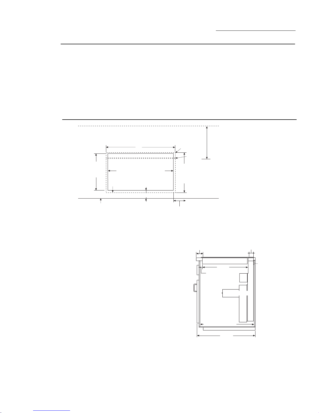
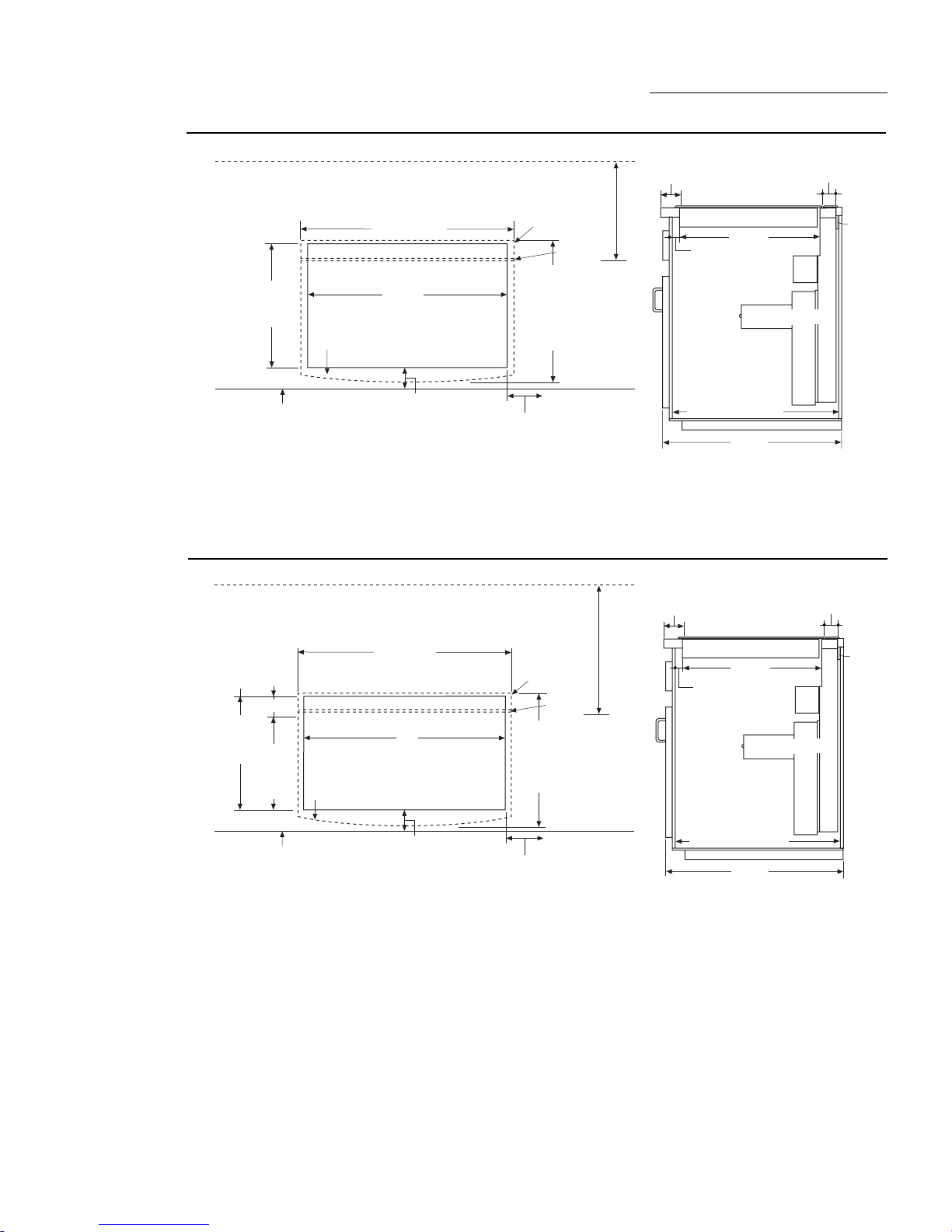
Cutouts and
Clearances
ZEU769
Electric Cooktops
with 36” Vent
• Measure carefully when cutting the
countertop. Make sure sides of the opening
are parallel and rear and front cuts are
exactly perpendicular to sides.
• Measure to be sure there is room for
clearances to the front edge of the
countertop.
• Refer to cooktop installation instructions
to be sure that models fit into the base
cabinets being used.
1-3/4" Min. Cooktop Cutout to Rear
Vertical Combustible Surface
36"
21-3/4"
Cutout
Depth
Front Edge
of Countertop
34" Cooktop and Vent Cutout
5/8" Cooktop Overlap
2-1/2" Min. Clearance to Cutout
2" Min. Cutout
to Side Walls
• Identify the cutout illustration for the
cooktop model you are installing.
– Draw lines on the countertop to follow as a
cutting guide. Measure and mark cooktop
and vent overlaps to be sure there is
enough flat countertop depth.
1/4" Overlap
1/8" Gap
22-1/2"
Total Flat
Surface
Required
Countertop Cutout: Requires 22-1/2" flat countertop
surface and 24-3/8" total countertop depth.
Cabinet: Requires 22-1/2" inside cabinet depth.
– Remove rear support rail.
2-1/2" to
Cutout
ZEU769 Cooktop
3/4"
22-3/4" to Back Wall
22" to Support Rail
19-7/8"
DOWNDRAFT VENT
24-3/4"
1-7/8"
3/4"
Thick
Support
Rail
6
Installation Preparation
3/4"
22-3/4" to Back Wall
22" to Support Rail
24-3/4"
2-1/2" to
Cutout
ZEU36 Cooktop
1-7/8"
3/4"
Thick
Support
Rail
19-7/8"
DOWNDRAFT VENT
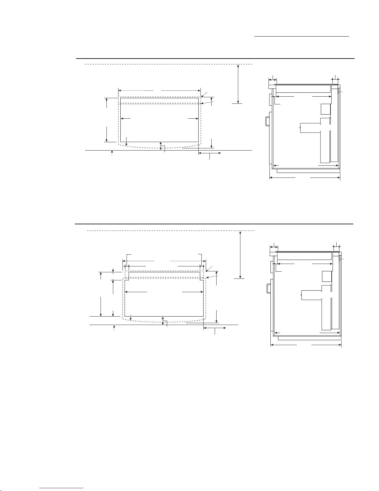
Downdraft Vent Systems
ZEU30R
Digital Cooktops
with 30" Vent
ZEU36R
Digital Cooktops
with 36" Vent
1-3/4" Min. Cooktop Cutout to Rear
Vertical Combustible Surface
29-7/8" (SS)
29-3/4" (B,W)
22-1/4"
Cutout
Depth
5/8" Cooktop Overlap
(1-1/8" at Center)
Front Edge
of Countertop
28-1/2"
Cooktop Area Cutout
2-1/2" Min.
Clearance to Cutout
2" Min. Cutout
to Side Walls
Countertop Cutout: Requires 23-3/8" (B,W) 23-1/2"
(SS) flat countertop surface. Requires 24-3/4" (B,W) and
24-7/8" (SS) total countertop depth.
1-3/4" Min. Cooktop Cutout to Rear
Vertical Combustible Surface
36-1/8" (SS)
36" (B,W)
2-3/4"
21-3/4"
Cutout
Depth
19-1/8"
Cooktop
Cutout
Depth
Cooktop and Vent Cutout
5/8" Cooktop Overlap
(1-1/8" at Center)
34"
1/4" Overlap
1/8" Gap
23-1/2" (SS)
23-3/8" (B,W)
Total Flat
Surface
Required
at Center
1/4" Overlap
1/8" Gap
23" (SS)
22-7/8" (B,W)
Total Flat
Surface
Required
2-1/2" to
Cutout
ZEU30 Cooktop
20-3/8"
3/4"
DOWNDRAFT VENT
22-3/4" to Back Wall
22" to Support Rail
24-3/4"
1-7/8"
Cabinet: Requires 23" inside cabinet
depth.
– See Creative Solutions, install in an
island or move cabinet base forward.
3/4"
Thick
Support
Rail
Front Edge
of Countertop
Countertop Cutout: Requires 22-7/8” (B,W) 23" (SS)
flat countertop surface. Requires 24-1/4" (B,W) and
24-3/8" (SS) total countertop depth.
2-1/2" Min.
Clearance to Cutout
2" Min. Cutout
to Side Walls
Cabinet: Requires 22-1/2" inside
cabinet depth.
–Remove rear support rail.
7
Installation Preparation
1"
22-3/4" to Back Wall
22" to Support Rail
24-3/4"
2-3/4" to
Cutout
ZGU375 Cooktop
1-7/8"
3/4"
Thick
Support
Rail
19-7/16"
DOWNDRAFT VENT
Downdraft Vent Systems
ZGU36GG
Gas Cooktops
with 36" Vent
ZGU375
Gas Cooktop
with 36" Vent
2-1/4" Min. Cooktop Cutout to Rear
Vertical Combustible Surface
36"
21-3/4"
Cutout
Depth
Front Edge
of Countertop
34" Cooktop and Vent Cutout
13/16" Cooktop Overlap
(1-1/2" at Center)
2-1/2" Min.
Clearance to Cutout
6" Min. Cutout
to Side Walls
Countertop Cutout: Requires 23-3/8" (B,W) 23-1/2"
(SS) flat countertop surface. Requires 24-3/8" (B,W) and
24-1/2" (SS) total countertop depth.
3-3/8" Min. Cooktop Cutout to Rear
Vertical Combustible Surface
9/16"
21-7/16"
Cutout
Depth
2-9/16"
18-7/8"
Cooktop
Cutout
9/16"
36-1/2"
34" Vent Cutout
35-5/16"Cooktop
Area Cutout
7/16" Cooktop Overlap
(1-1/4" At Center)
1/4" Overlap
1/8" Gap
23-1/2" (SS)
23-3/8" (B,W)
Total Flat
Surface
Required
at Center
1/4" Overlap
1/8" Gap
22-3/4"
Total Flat
Surface
Required
2-1/2" to
Cutout
ZGU36 Cooktop
20-1/16"
3/4"
DOWNDRAFT VENT
22-3/4" to Back Wall
22" to Support Rail
24-3/4"
1-7/8"
Cabinet: Requires 22-11/16" inside
cabinet depth.
–Remove rear support rail.
3/4"
Thick
Support
Rail
Front Edge
of Countertop
8
Countertop Cutout: Requires 22-3/4” flat countertop
surface and 24-1/4" total countertop depth.
2-3/4" Min.
Clearance to Cutout
7-9/16" Min. Cutout
to Side Walls
Cabinet: Requires 22-5/16" inside
cabinet depth.
–Remove rear support rail.
 Loading...