

Monogram ZV42I, ZV54I Installation Instructions Manual
Installation
Instructions
Island VentHoods
Models:
ZV42I
ZV54I
0
Monogram:
Installation Instructions
BEFORE YOU BEGIN
Read these instructions completely and
carefully.
• IMPORTANT- Savetheseinstructions for local
inspector'suse.
• IMPORTANT- Observe all governing codes and
ordinances.
• Note to Installer - Be sure to leave these
instructions with the Consumer.
• Note to Consumer- Keep these instructions for
future reference.
• Skill Level - installation of this vent hood requires
basic mechanical and electrical skills.
• Completion time - 1to 3 hours.
• Proper installation isthe responsibility of the installer.
• Product failure due to improper installation is not
covered under the Warranty.
A CAUTION:
Due to the weight and size of these vent
hoods and to reduce the risk of personal injury or
damage to the product, THREE PEOPLEARE REQUIRED
FOR PROPERINSTALLATION.
A PRUDENCE
_, cause du poids et des dimensions du ces
hottes et pour r6duire les risques de blessures ou de
dommages du produit, IL FAUT TROIS PERSONNES
POUR FAIRE UNE INSTALLATION CORRECTE.
A WARNING:
To reduce the risk of fire or electrical shock,
do not use this range hood with any external solid-state
speed control device. Any such alteration from original
factory wiring could result in damage to the unit and/or
create an electrical safety hazard.
A ADVERTISSEMENT
Pour r_duire le risque d'incendie ou de
choc _lectrique, il ne faut pas utiliser cette hotte avec
un r_gulateur de vitesse _lectronique externe. Toute
modification de ce type du branchement d'usine peute
endommager I'appareil ou crier un risque de choc
_lectrique.
TO REDUCETHE RISK OFFIRE, USE ONLY METAL
DUCTVVORK.
WARNING: TO REDUCETHE
RISK OFFIRE, ELECTRICALSHOCK OR
INJURY, OBSERVETHE FOLLOWING:
A. Use this unit only in the manner intended by the
manufacturer. If you have any questions, contact the
manufacturer.
B. Before servicing or cleaning unit, switch power
off atthe service panel and lock service panel to
prevent power from being switched on accidentally.
If the service panel cannot be locked, fasten a tag or
prominent warning label to the panel.
A ADVERTISSEMENT
POUR REDUIRE LE RISQUE D'INCENDIE, DE
CHOC ELECTRIQUEOU DE BLESSURES, IL
FAUT OBSERVERLES REGLESSUIVANTES:
A. Utiliser cet appareil uniquement de la mani_re
pr6vue par le fabricant. En cas de question,
consulter le fabricant.
B. Avant toute intervention ou nettoyage, couper
ralimentation _lectrique au disjoncteur et verrouiller
le panneau du disjoncteur pour _viter la mise sous
tension accidentelle. S'il n'est pas possible de
verrouiller le panneau du disconcteur, attacher un
placard ou une Otiquette trOs visible au panneau.
• For general ventilating use only. Do not use to exhaust
hazardous or explosive materials or vapors.
• Structural framing, installation work and electrical
wiring must be done by qualified person(s). In
accordance with all applicable codes and standards
including fire-rated construction.
• Sufficient air is needed for proper combustion and
exhausting of gases through the flue (chimney) of fuel
burning equipment to prevent back drafting. Follow
the heating equipment manufacturer's guideline and
safety standards such as those published by the
National Fire Protection Association (NFPA), and the
American Society for Heating, Refrigeration and Air
Conditioning Engineers (ASHRAE), and the local code
authorities.
• Local codes vary. Installation electrical connections
and grounding must comply with applicable codes.
in the absence of local codes, the vent should be
installed in accordance with National Electrical
Code ANSI/NFPA 70-1990 or latest edition.
A CAUTION: To reduce risk of fire
and to properly exhaust air, be sure to duct
air outside - Do not vent exhaust air into
spaces within walls or ceilings or into attics, crawl
spaces, or garages.
PRUDENCE, fautprendre
soin d'installer un conduit vers I'ext_rieur
pour r6duire le risque d'incendie et pouvoir
_vacuer Fair correctement. II ne faut pas _vacuer
I'air correctement. II ne faut pas _vacuer Fair dans
I'espace entre les parois d'un mur, un plafond ou un
grenier, un espace sanitaire ou un garage.
Design Information
CONTENTS
Design Information
Product Dimensions......................................................................3
DuctCoverAccessories..............................................................4
Product Clearances......................................................................4
Advance Planning
DuctworkPlanning ......................................................................5
CeilingFramingfor Support ........................................................5
AccessoryFramesandDuct Covers ........................................5
Power Supply ................................................................................5
InstallationHeight ........................................................................6
DuctFittings..................................................................................7
Installation Preparation
ToolsandMaterialsRequired....................................................8
Removethe Packaging................................................................8
Parts,Hardware,Accessory Packages ..................................9
Installation Instructions
Step 1,Construct CeilingSupport......................................10-12
Step2, MountTemplate..............................................................13
Step3, Size andInstallDuctwork............................................13
Step4, InstallSupport Frameand DuctCovers....................14
Step 5,InstallDuctTransitionand Damper ..........................15
Step6, InstallHoodto Support ................................................15
Step7, Connect Duct ................................................................15
Step8, Connect Electrical..........................................................16
Step9, Installthe Motor ............................................................16
Step 10,Slide DuctCover down ..............................................17
Step 11,InstallFilters..................................................................17
Step 12,InstallRods....................................................................17
Step 13,InstallSupplied DuctCover,TopCover....................18
Step 14,FinalizeInstallation......................................................18
Step 15,InstallationChecklist ..................................................19
42" HOOD DIMENSIONS 54" HOOD DIMENSIONS
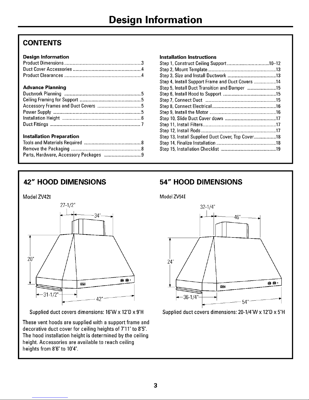
Model ZV421
27-1/2"
Supplied duct covers dimensions: 16"Wx 12"Dx9"H
These vent hoods are supplied with a support frame and
decorative duct cover for ceiling heights of 7'1I" to 8'5".
The hood installation height is determined by the ceiling
height. Accessories are available to reach ceiling
heights from 8"6"to 10'4".
Model ZV54[
32-1/4"
24"// _
Supplied duct covers dimensions: 20-1/4'W x 12"[1x 5"H
Design Information
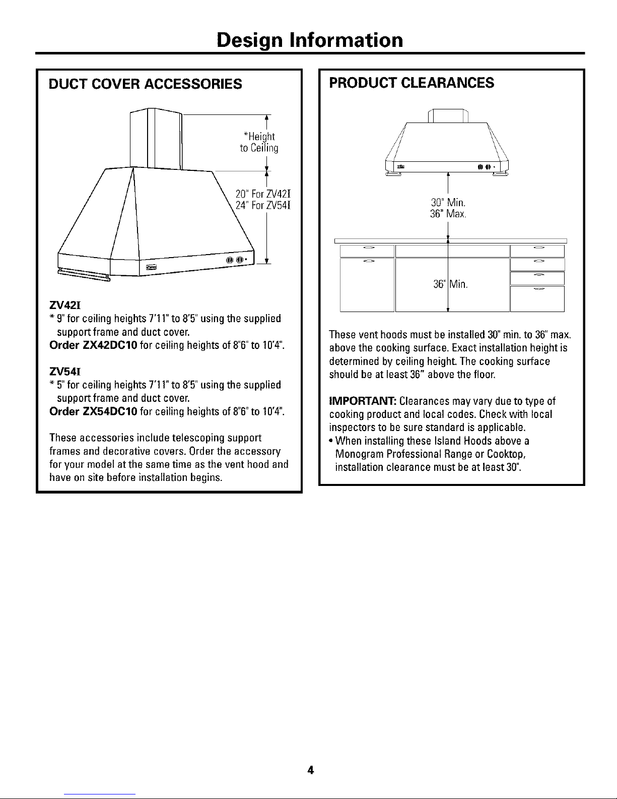
DUCT COVER ACCESSORIES
ZV42!
* 9"for ceiling heights 7'11" to 8"5" using the supplied
support frame and duct cover.
Order ZX42DC10 for ceiling heights of 8"6"to 10'4".
ZV54!
* 5"for ceiling heights 7'11" to 8"5" using the supplied
support frame and duct cover.
Order ZX54DC10 for ceiling heights of 8"6"to 10'4".
These accessories include telescoping support
frames and decorative covers. Order the accessory
for your model at the same time as the vent hood and
have on site before installation begins.
PRODUCT CLEARANCES
[
30" Min.
36" Max.
36" Min.
These vent hoods must be installed 30" min. to 36"max.
above the cooking surface. Exact installation height is
determined by ceiling height. The cooking surface
should be at least 36" above the floor.
IMPORTANT: Clearances may vary due to type of
cooking product and local codes. Check with local
inspectors to be sure standard is applicable.
• When installing these Island Hoods above a
Monogram Professional Range or Cooktop,
installation clearance must be at least 30".
4
Advance Planning
ADVANCE PLANNING
Ductwork Planning
• These vent hoods are equipped for 10" round
ductwork.
• Determine the exact location of the vent hood.
• Plan the route for venting exhaust to the outdoors.
• Use the shortest and straightest duct route possible.
For satisfactory performance, duct run should not
exceed 150ft. equivalent length for any duct
configurations.
• Refer to "Duct Fittings" chart to compute the
maximum permissible length for duct runs to the
outdoors.
• Use rigid metal ductwork only.
• Install a roof cap with damper at the exterior opening.
Order the cap and any transitions needed in advance.
Ceiling Framing for Adequate Support
•These vent hoods are heavy. Adequate structural
support must be provided. The ceiling structure must
be capable of supporting the weight of the hood and
any inadvertent user contact loads (approximately 300
pounds). The hood support frame will be supported by
2 x 4 cross framing.
Accessory Frames and Duct Covers
• All models are shipped with a support frame and duct
covers for ceilings heights of7'11"to 8'5".
• Optional accessories include telescoping support
frames and duct covers to reach 8'6" and up to
10'4" ceiling heights.
• Optional accessories must be ordered with the hood
and be on site before final framing and wall finishing.
Mounting the hood without a support frame
The distance between the cooking surface and the
bottom of the hood must be 30"to 36".In situations
where the ceiling is low, the hoods may be secured
directly to the ceiling without the supplied frame.
Use the bottom of the supplied support frame as a
template to locate the mounting holes in the top of the
hood. Use shimson the ceiling joists or cross framing
in the mounting hole locations. This will allow the
mounting screws to engage the recessed keyhole
slots in the top ofthe hood.See Step 2.
POWER SUPPLY
IMPORTANT - (Please read carefully)
WARNING:
FOR PERSONAL SAFETY,THIS APPLIANCE
MUST BEPROPERLYGROUNDED.
ATTENTION POURDES
RAISONS DE St_CURITt_,CET APPAREIL
D01T ETRECORRECTEMENT MIS _, LA TERRE.
Remove house fuse or open circuit breaker before
beginning installation.
Do not use an extension cord or adapter plugwith
this appliance. Follow National electrical codes or
prevailing local codes and ordinances.
Electrical Supply
This vent hood must be supplied with 120V,60Hz,
and connected to an individual, properly grounded
branch circuit, and protected by a 15 or 20 amp
circuit breaker or time delay fuse.
• Wiring must be 2wire with ground.
• If the electrical supply does not meet the above
requirements, call a licensed electrician before
proceeding.
• Route house wiring in the ceiling, as close to the
installation location as possible. Allow additional
length from ceiling joists to reach the junction box
on the bottom of the hood support frame.
• Connect the wiring to the house wiring in accordance
with local codes.
Grounding Instructions
The grounding conductor must be connected to
a ground metal, permanent wiring system, or an
equipment-grounding terminal or lead on the hood.
WARNING: The improper
connection of equipment-grounding
conductor can result in a risk of electric shock. Check
with a qualified electrician or service representative if
you are in doubt whether the appliance is properly
grounded.
ADVERTISSEMENT
Le mauvais branchement du fil de raise
la terre peut causer an choc 01ectriqae. Encas
de doute, consulter an 01ectricien qualifi0 ou an
technicien pour d0terminer si I'appareil est a la terre.
Advance Planning
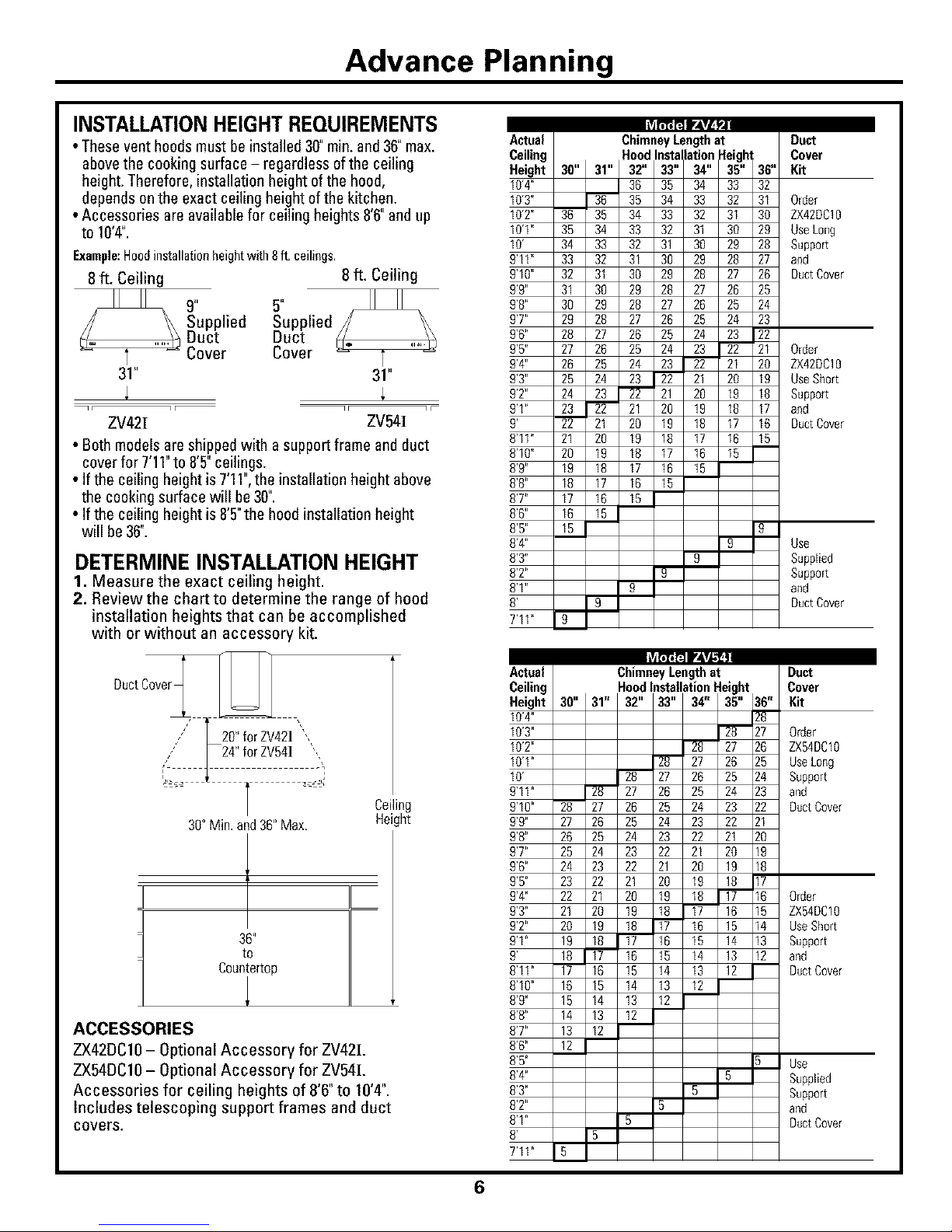
INSTALLATIONHEIGHT REQUIREMENTS
• Theseventhoodsmustbe installed 30"rain.and36"max.
abovethe cookingsurface- regardless ofthe ceiling
height.Therefore,installation heightof thehood,
dependsonthe exact ceilingheightofthe kitchen.
• Accessories are availablefor ceilingheights8'6"andup
to 10'4".
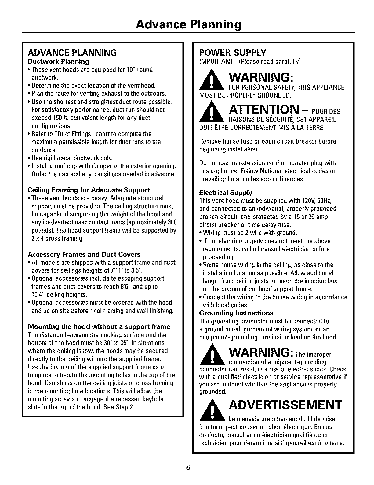
Example:Hoodinstallationheightwith 8ft, ceilings.
8 ft. Ceiling 8 ft. Ceiling
Supplied Supplied
Duct Duct
Cover Cover
31" 31"
ZV42[ ZV541
• Both models are shippedwith asupportframe andduct
cover for 7'11"to 8'5" ceilings.
• If the ceiling height is7'11",the installation height above
the cooking surfacewill be30".
• If the ceiling height is 8'5"the hood installation height
will be 36".
DETERMINE INSTALLATION HEIGHT
1. Measure the exact ceiling height.
2. Review the chart to determine the range of hood
installation heightsthat can be accomplished
with or without an accessory kit.
DuctCover
20"forZV421 ",
24"forZV541
i
30" Min. and 36" Max
Ceilir
Height
36"
to
Countertop
ACCESSORIES
ZX42DC10- Optional Accessory for ZV42[.
ZX54DC10- Optional Accessory for ZV54[.
Accessories for ceiling heights of 8'6" to 10'4".
Includes telescoping support frames and duct
covers.
Actual Chimney Length at Duct
Ceiling Hood Instalatio,n _'leight . Cover
Height 30" 31" 32 133 34 135 136 Kit
9
g
9
10'4" 36 35 34 33 32
10'3" 36 35 34 33 32 31 Order
10'2" 36 35 34 33 32 31 30 ZX42DC10
10'1" 35 34 33 32 31 30 2g Use Long
10' 34 33 32 31 30 29 28 Support
g'11" 33 32 31 30 29 28 27 and
9'10" 32 31 30 29 28 27 26 Duct Cover
9'9" 31 30 29 28 27 26 25
9'8" 30 29 28 27 26 25 24
9'7" 2g 28 27 26 25 24 23
9'6" 28 27 26 25 24 23 22
9'5" 27 26 25 24 23 22 21 Order
9'4" 26 25 24 23 22 21 20 ZX42DC10
9'3" 25 24 23 22 21 20 19 Use Short
9'2" 24 23 22 21 20 19 18 Support
9'1" 23 22 21 20 19 18 17 and
9' 22 21 20 19 18 17 16 Duct Cover
8'11" 21 20 19 18 17 16 15
8'10" 20 19 18 17 16 15
8'9" 19 18 17 16 15
8'8" 18 17 16 15
8'7" 17 16 15
8'6" 16 15
8'5" 15 g
8'4" 9 Use
8'3" 9 Supplied
8'2" Support
8'1" and
8' Duct Cover
7'11" I g
_,ctual Chimney Length at Duct
:eiling Hood Ins2[lation Height . Cover
4eight 30"131"I32 133I34 I3s 136Kit
W4"
10'3" 28 27 Order
10'2" 128 27 26 ZX54DC10
IO'l" _-- 27 26 25 UseLong
IO' 28 27 26 25 24 Support
_'11" 28 27 26 25 24 23 and
_'10" 28 27 26 25 24 23 22 Duct Cover
_'g" 27 26 25 24 23 22 21
_'8" 26 25 24 23 22 21 20
_'7" 25 24 23 22 21 20 19
_'6" 24 23 22 21 20 19 18
_'5" 23 22 21 20 19 18 17
_'4" 22 21 20 19 18 17 16 Order
_'3" 21 20 19 18 17 16 15 ZXS4DC10
_'2" 20 19 18 17 16 15 14 UseShort
_'1" 19 18 17 16 15 14 13 Support
_' 18 17 16 15 14 13 12 and
_'11" 17 16 15 14 13 12 DuctCover
_'10" 16 15 14 13 12
_'g" 15 14 13 12
_'8" 14 13 12
_'7" 13 12
_'6" 12
_'5" 5 Use
_'4" 5 Supplied
_'3" Support
_'2" 5 and
_'1" 5 Duct Cover
_' 5
7'11" 5
6
 Loading...