

Monogram ZV48R, ZV36R, ZV30R Installation Instructions Manual

Installation
Instructions
If you have questions, call 800-GE-CARES or visit our website at: www.monogram.com
30", 36" and 48"
Restaurant Style
Vent Hoods
Models:
ZV48R
ZV36R
ZV30R
Monogram.
®
We bring good things to life.
1
Installation Instructions
BEFORE YOU BEGIN
Read these instructions completely and carefully.
• IMPORTANT - Save these instructions for
local inspector’s use.
• IMPORTANT - Observe all governing codes
and ordinances.
• Note to Installer - Be sure to leave these instructions
with the Consumer.
• Note to Consumer - Keep these instructions for
future reference.
• Skill Level – Installation of this vent hood requires
basic mechanical and electrical skills.
• Completion time – 1 to 3 hours.
• Proper installation is the responsibility of the installer.
• Product failure due to improper installation is not
covered under the Warranty.
CAUTION:
Due to the weight and size of these vent hoods and to
reduce the risk of personal injury or damage to the
product, TWO PEOPLE ARE REQUIRED FOR
PROPER INSTALLATION.
PRUDENCE
À cause du poids et de la taille de ces hottes et pour
reduire le risque de blessures et de dommages, IL FAUT
DEUX PERSONNES POUR FAIRE L’INSTALLATION
CORRECTEMENT.
WARNING:
To reduce the risk of fire or electrical shock, do not use
this range hood with any external solid-state speed
control device. Any such alteration from original factory
wiring could result in damage to the unit and/or create
an electrical safety hazard.
ADVERTISSEMENT
Pour réduire le risque d’incendie ou de choc électrique,
il ne faut pas utiliser cette hotte avec un régulateur de
vitesse électronique externe. Toute modification de ce
type du branchement d’usine peute endommager
l’appareil ou créer un risque de choc électrique.
TO REDUCE THE RISK OF FIRE, USE ONLY METAL
DUCTWORK.
WARNING:
TO REDUCE THE RISK OF FIRE, ELECTRICAL
SHOCK OR INJURY TO PERSONS, OBSERVE THE
FOLLOWING:
A. Use this unit only in the manner intended by the
manufacturer. If you have any questions, contact the
manufacturer.
B. Before servicing or cleaning unit, switch power off at
the service panel and lock service panel to prevent
power from being switched on accidentally. If the
service panel cannot be locked, fasten a tag or
prominent warning label to the panel.
ADVERTISSEMENT
POUR RÉDUIRE LE RISQUE D’INCENDIE, DE
CHOC ÉLECTRIQUE OU DE BLESSURES, IL FAUT
OBSERVER LES REGLES SUIVANTES:
A. Utiliser cet appareil uniquement de la maniére
prévue par le fabricant. En cas de question, consulter
le fabricant.
B. Avant toute intervention ou nettoyage, couper
l’alimentation électrique au disjoncteur et
verrouiller le panneau du disjoncteur pour éviter la
mise sous tension accidentelle. S’il n’est pas possible
de verrouiller le panneau du disconcteur, attacher
un placard ou une étiquette trés visible au panneau.
• For general ventilating use only. Do not use to exhaust
hazardous or explosive materials or vapors.
• Structural framing, installation work and electrical
wiring must be done by qualified person(s). In
accordance with all applicable codes and standards
including fire-rated construction.
• Sufficient air is needed for proper combustion and
exhausting of gases through the flue (chimney) of fuel
burning equipment to prevent back drafting. Follow
the heating equipment manufacturer’s guideline and
safety standards such as those published by the
National Fire Protection Association (NFPA), and the
American Society for Heating, Refrigeration and Air
Conditioning Engineers (ASHRAE), and the local
code authorities.
• Local codes vary. Installation electrical connections
and grounding must comply with applicable codes. In
the absence of local codes, the vent should be installed in accordance with National Electrical Code
ANSI/NFPA 70-1990 or latest edition.
CAUTION: To reduce risk of fire and to
properly exhaust air, be sure to duct air outside – Do
not vent exhaust air into spaces within walls or ceilings
or into attics, crawl spaces, or garages.
PRUDENCEIl faut prendre soin d’installer
un conduit vers l’extérieur pour réduire le risque
d’incendie et pouvoir évacuer l’air correctement. Il ne
faut pas évacuer l’air correctement. Il ne faut pas
évacuer l’air dans l’espace entre les parois d’un mur, un
plafond ou un grenier, un espace sanitaire ou un
garage.
2
Installation Instructions
CONTENTS
Product Dimensions .........................................................3
Installation Clearances .....................................................4
Optional Duct Cover Accessories .................................... 4
Advance Planning .............................................................5
Power Supply .................................................................... 5
Duct Fittings...................................................................... 6
Using Duct Cover Accessories.......................................... 7
Tools and Materials Required .......................................... 8
Remove the packaging ..................................................... 8
Parts Provided ...................................................................9
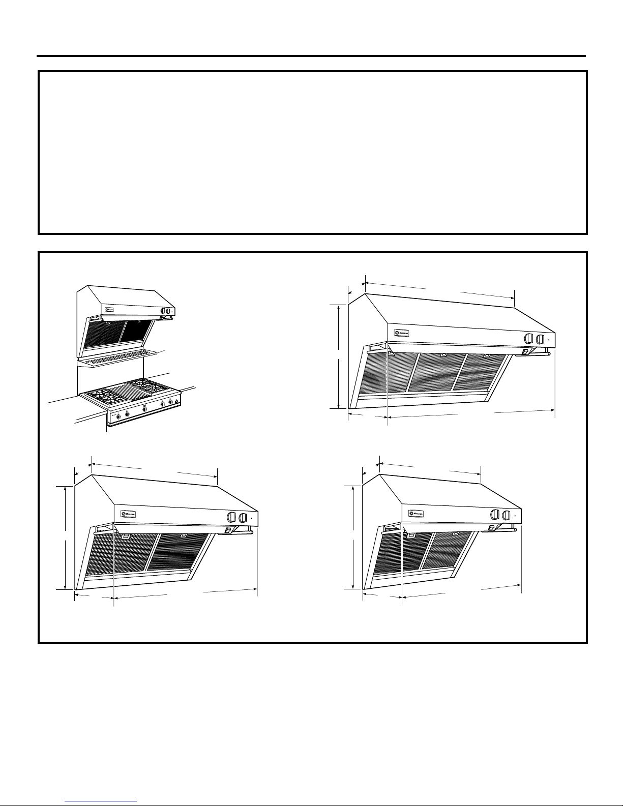
PRODUCT DIMENSIONS
Each hood is
shipped with a
stainless steel
Warming
Shelf
Backguard
backguard and a
warming shelf.
Hoods may be
installed with the
shelf or backguard
alone, or with both
as shown.
Step 1, Determine Ductwork and Wiring Locations .... 10
Step 2A, Install Hood Onto Wall ................................... 11
Step 2B, Install Hood Beneath Soffit ............................ 12
Step 3, Connect Ductwork ............................................. 13
Step 4, Connect Electrical..............................................13
Step 5, Install Duct Covers ............................................. 13
Step 6, Install Motor .......................................................13
Step 7, Install Filters ....................................................... 14
Step 8, Install Backguard and Shelf............................... 14
Step 9, Install Shelf Only................................................15
Step 10, Install Implement Rods ................................... 15
12"
22-1/2"
25"
47-15/16"
47-15/16"
12"
22-1/2"
Model ZV36R
25"
35-15/16"
35-15/16"
Model ZV48R
22-1/2"
Model ZV30R
12"
25"
29-15/16"
29-15/16"
3
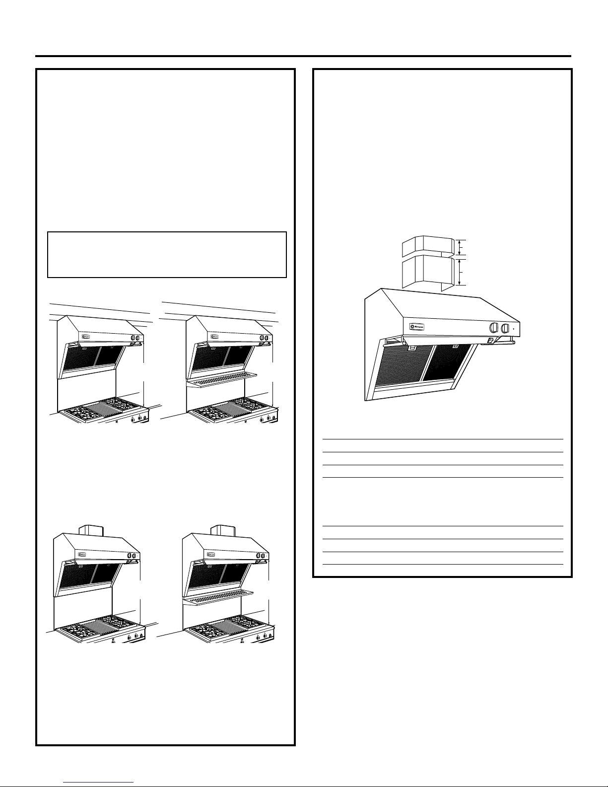
Advance Planning
INSTALLATION CLEARANCES
These vent hoods are designed to be installed onto a
wall or beneath a soffit or cabinet.
Installation with Warming Shelf
• Hoods must be installed 32" Min., 38" Max over any
type cooking surface when warming shelf is used.
Installation without Warming Shelf
• Install these hoods 30" Min. to 36" Max. above the
cooking surface when installed over any professional
style cooktop or range.
• These hoods may be installed 24" min. above a gas or
electric drop-in style cooktop.
Note: Clearances may vary due to type of cooking product and
local codes. Check with local inspectors to be sure standard is
applicable.
Soffit Installation
SOFFIT
30" Min.
36" Max.
SOFFIT
32" Min.
38" Max.
OPTIONAL DUCT COVER
ACCESSORIES
Decorative duct covers are available in 6" and 12"
heights. Duct covers may be stacked, in various
combinations, to conceal the ductwork running from
the top of the hood to the ceiling.
• Before you begin, you should determine the installation height of the hood and order the correct size
duct cover. The duct covers should be ordered at the
same time as the vent hood and be on site before
installation. Order the duct cover corresponding to
your model.
6" Duct Cover
12" Duct Cover
Install these hoods 30" Min. to
36" Max. over a professional
style cooktop or range.
Allow 32" min. and 38" max.
clearance above any cooking
surface when installed with shelf.
In this installation the ductwork running from the top
of the hood will be concealed in the soffit or upper
cabinetry.
Wall Mount Installation
30" Min.
36" Max.
Install these hoods 30" Min. to
36" Max. over a professional
style cooktop or range.
Allow 32" min. and 38" max.
clearance above any cooking
surface when installed with shelf.
32" Min.
38" Max.
For this installation, a decorative duct cover is available to conceal the ductwork running from the top of
the hood. Use of the duct cover requires special
consideration to the installation height above the
countertop.
6" Duct Covers
Hood Model 6” Duct Cover Dimensions
ZV48R ZX48DC6 6"H x 19-11/16"W x 11-7/8"D
ZV36R ZX36DC6 6"H x 15-3/4"W x 11-7/8"D
ZV30R ZX36DC6 6"H x 15-3/4"W x 11-7/8"D
12" Duct Covers
Hood Model 12” Duct Cover Dimensions
ZV48R ZX48DC12 12"H x 19-11/16"W x 11-7/8"D
ZV36R ZX36DC12 12"H x 15-3/4"W x 11-7/8"D
ZV30R ZX36DC12 12"H x 15-3/4"W x 11-7/8"D
4
Advance Planning
ADVANCE PLANNING
Ductwork Planning
• These vent hoods are equipped for 10" round
ductwork. In most instances they may be transitioned
to 8" round.
• This hood may be vented vertically through upper
cabinets, soffit or ceiling. A duct transition piece is
supplied for vertical exhaust. Use locally supplied
elbows to vent horizontally through the rear wall.
• Determine the exact location of the vent hood.
• Plan the route for venting exhaust to the outdoors.
• Use the shortest and straightest duct route possible.
For satisfactory performance, duct run should
not exceed 150 ft. equivalent length for any duct
configurations.
• Refer to “Duct Fittings” chart to compute the maximum permissible length for duct runs to the outdoors.
• Use metal ductwork only.
• Install a wall cap or roof cap with damper at the
exterior opening. Order the wall or roof cap and any
transition needed in advance.
Wall Framing for Adequate Support
• These vent hoods are heavy. Adequate structural
support must be provided. Hoods must be secured to
vertical studs in the wall.
• It is strongly recommend that the vent hood with
duct cover be on site before final framing and wall
finishing. This will also help to accurately locate the
ductwork and electrical service.
Decorative Duct Covers:
Decorative duct covers, 6" and 12" high, are available to
fit all models. The duct cover conceals the ductwork
running from the top of the hood to the ceiling or
soffit. Stack one or more duct covers over the top of
the hood to reach your ceiling height.
POWER SUPPLY
IMPORTANT - (Please read carefully)
WARNING:
FOR PERSONAL SAFETY, THIS APPLIANCE MUST
BE PROPERLY GROUNDED.
ATTENTION – POUR DES RAISONS
DE SÉCURITÉ, CET APPAREIL DOIT ÊTRE
CORRECTEMENT MIS À LA TERRE.
Remove house fuse or open circuit breaker before
beginning installation.
Do not use an extension cord or adapter plug with this
appliance. Follow National electrical codes or prevailing local codes and ordinances.
Electrical supply
These vent hoods must be supplied with 120V, 60Hz,
and connected to an individual, properly grounded
branch circuit, and protected by a 15 or 20 amp circuit
breaker or time delay fuse.
• Wiring must be 2 wire with ground.
• If the electrical supply does not meet the above
requirements, call a licensed electrician before
proceeding.
• Route house wiring as close to the installation
location as possible on the back wall or ceiling.
• Connect the wiring to the house wiring in accordance with local codes.
Grounding instructions
The grounding conductor must be connected to a
ground metal, permanent wiring system, or an equipment-grounding terminal or lead on the hood.
WARNING: The improper connection of
the equipment-grounding conductor can result in a
risk of electric shock. Check with a qualified electrician
or service representative if you are in doubt whether
the appliance is properly grounded.
ADVERTISSEMENT
Le mauvais branchement du fil de mise à la terre peut
causer un choc électrique. En cas de doute, consulter
un électricien qualifié ou un technicien pour
déterminer si l’appareil est à la terre.
5
 Loading...