

Page 1

INSTALLATION
INSTRUCTIONS
with Design Guide
Flush Inset Installation for Built-In Refrigerators
Pour obtenir une version française de ce manuel d’instructions,
visitez notre site monogram.com.
Para consultar una version en español de este manual de instrucciones,
visite nuestro sitio de internet monogram.com.
MONOGRAM.COM
Page 2

Safety Information
BEFORE YOU BEGIN
Read these instructions completely and carefully.
IMPORTANT – Save these instructions for
•
local inspector’s use. Observe all governing codes and
ordinances.
Note to Installer – Be sure to leave these
•
instructions with the Consumer.
• Note to Consumer – Keep these instructions with
your Owner’s Manual for future reference.
If you received a damaged unit, you should immediately
contact your dealer or builder.
Skill Level – Installation of this unit requires basic
mechanical, carpentry and plumbing skills. Proper
installation is the responsibility of the installer. Product
failure due to improper installation is not covered under
the Monogram Warranty. See the Owner’s Manual for
warranty information.
WARNING
Plug into a grounded 3-prong outlet.
Do not remove the ground prong.
Do not use an adapter.
Immediately discontinue use of a damaged supply cord.
If the supply cord is damaged it must be replaced by a
qualified service professional with an authorized service
part from the manufacturer.
WARNING
Electrical Shock Hazard.
Do not use an extension cord with this appliance.
Failure to follow these instructions can result in death,
fire, or electrical shock.
Follow the instructions in the section Grounding the unit.
This appliance must be installed with a means in the
fixed house wiring or circuit breaker for disconnecting the
appliance from the electrical supply after installation.
Tip Over Hazard.
These appliances are top heavy, especially with any doors open, and must be secured to prevent tipping
forward which could result in death or serious injury. Read and follow the entire installation instructions for
securing the appliance with the anti-tip system.
WARNING
Fire or Explosion Hazard.
Keep flammable materials and vapors away from appliance. Failure to do so can result in fire, explosion,
or death.
WARNING
To reduce the risk associated with choking, do not allow children under 3 years of age to
have access to small parts during the installation of this product.
CAUTION
Lifting Hazard
This unit is very heavy. To reduce the risk of person injury during maneuvering and installing this appliance,
3 people are required for proper installation.
CAUTION
Keep fingers out of the “pinch point” areas; clearances between the doors and between the
doors and cabinet are necessarily small. Be careful closing doors when children are in the area.
For Monogram local service in your area, visit monogram.com
For Monogram service in Canada, visit monogram.ca
For Monogram Parts and Accessories, visit monogram.com/use-and-care/parts
2
31-1000454 Rev. 2
Page 3

Consignes de sécurité
AVANT DE COMMENCER
Veuillez lire toutes ces instructions attentivement.
• IMPORTANT – Conservez ces instructions à
l’usage de l’inspecteur local. Observez tous les codes et
décrets en vigueur.
Note à l’installateur – Assurez-vous de laisser ces
•
instructions au consommateur.
Note au consommateur - Conservez ces instructions
•
avec votre manuel d’utilisation pour
Si vous avez reçu un appareil endommagé, veuillez
communiquer immédiatement avec votre revendeur ou votre
entrepreneur.
consultation ultérieure.
Niveau de compétence – L’installation de cet appareil
exige des compétences de base en mécanique, menuiserie
et plomberie. La responsabilité d’une installation adéquate
relève de l’installateur. La garantie Monogram ne couvre
pas les défectuosités du produit causées par une installation
inadéquate. Consultez le manuel d’utilisation pour des
renseignements sur la garantie.
AVERTISSEMENT
Branchez l’appareil dans une prise à 3 broches mise à la terre.
N’enlevez pas la broche de mise à la terre.
N’utilisez pas un adaptateur.
Cessez immédiatement l’utilisation d’un cordon électrique
endommagé. Si le cordon électrique est endommagé, son
remplacement doit être exécuté par un technicien en réparation
qualifié au moyen d’un cordon de rechange autorisé par le
fabricant.
AVERTISSEMENT
Ces électroménagers sont lourds du haut, notamment lorsqu’une porte est ouverte, de sorte qu’ils doivent être fixés pour
prévenir un basculement vers l’avant susceptible d’occasionner des blessures graves ou la mort. Lisez et observez la totalité des
instructions d’installation pour connaître la façon de fixer l’électroménager sur le dispositif antibasculement.
AVERTISSEMENT
Gardez les matériaux et les vapeurs inflammables à l’écart de l’appareil. L’omission de prendre cette précaution peut entraîner un
incendie, une explosion ou la mort.
AVERTISSEMENT
à la portée des enfants âgés de moins de 3 ans.
Risque d’électrocution.
N’utilisez pas un cordon de rallonge avec cet électroménager.
Le non-respect de ces instructions peut occasionner un décès,
un incendie ou un choc électrique
Suivez les instructions de la section Mise à la terre de l’appareil.
Le circuit électrique auquel cet électroménager sera raccordé
doit comporter un disjoncteur ou un autre dispositif permettant
de couper l’alimentation électrique à l’appareil après l’installation.
Risque de basculement.
Risque d'incendie ou d'explosion.
Pour réduire le risque d’étouffement pendant l’installation de ce produit, ne pas laisser les petites pièces
AVERTISSEMENT
Cet appareil est très lourd. Afin de réduire le risque de blessure pendant la manipulation et l’installation de cet électroménager, la
participation de 3 personnes est nécessaire à l’exécution d’une installation correcte.
AVERTISSEMENT
portes et l’armoire sont particulièrement restreints. Soyez prudent lorsque vous fermez les portes en présence d’enfants.
Pour joindre le service Monogram de votre région, visitez monogram.com
Pour le service Monogram au Canada, visitez monogram.ca
Pour le service des Pièces et accessoires Monogram, visitez monogram.com/use-and-care/parts.
31-1000454 Rev. 2
Risque lié à la manipulation d’un objet lourd
Gardez vos doigts éloignés des points de pincement. Les espaces entre les portes et ceux entre les
3
Page 4

Información sobre Seguridad
ANTES DE COMENZAR
Lea estas instrucciones en su totalidad y atentamente.
IMPORTANTE – Conserve estas
•
instrucciones para uso del inspector local. Cumpla con
todos los códigos y ordenanzas gubernamentales.
Nota para el Instalador – Asegúrese de entregarle
•
estas instrucciones al Comprador.
• Nota para el Consumidor – Guarde estas
instrucciones con su Manual del Propietario para
referencia futura.
Si la unidad que recibió está dañada, se deberá
comunicar de inmediato con su vendedor o fabricante.
Nivel de habilidad – La instalación de esta unidad
requiere un nivel básico de habilidades mecánicas,
de carpintería y plomería. La correcta instalación
del producto es responsabilidad del instalador. Si se
producen fallas en el producto debido a una instalación
inadecuada, la Garantía de Monogram no cubrirá las
mismas. Para obtener información sobre la garantía,
consulte el Manual del Propietario.
ADVERTENCIA
Enchufe en un tomacorriente con conexión a tierra de 3
cables.
No elimine el cable de conexión a tierra.
No use un adaptador.
Inmediatamente interrumpa el uso de un cable de
suministro de corriente dañado. Si el cable de corriente se
encuentra dañado, su reemplazo deberá ser realizado por
un profesional calificado del servicio técnico, utilizando una
pieza del servicio técnico autorizada por el fabricante.
ADVERTENCIA
Estos electrodomésticos son inestables, especialmente cuando una puerta se encuentre abierta, y deben estar
asegurados a fin de evitar caídas hacia adelante que podrían resultar en la muerte o en lesiones graves. Lea y siga
las instrucciones de instalación en su totalidad para asegurar el electrodoméstico con el sistema anti volcaduras.
ADVERTENCIA
Mantenga cualquier material y vapores inflamables alejados del electrodoméstico. Si no se cumple con esto, se podrá
producir una explosión, un incendio o la muerte.
ADVERTENCIA
años de edad tengan acceso a las partes pequeñas durante la instalación de este producto.
Riesgo de Descarga Eléctrica
No use prolongadores con este electrodoméstico.
Si no se siguen estas instrucciones, se podrá producir la
muerte, incendios o descargas eléctricas.
Siga las instrucciones que figuran en la sección de
Conexión de Tierra de la unidad.
Este electrodoméstico deberá ser instalado por algún
medio en el cableado fijo del hogar o en un disyuntor para
desconectar el electrodoméstico del suministro eléctrico
luego de la instalación.
Riesgo de Caídas
Peligro de Incendio o Explosión
A fin de reducir el riesgo asociado con descargas, no permita que los niños menores de 3
PRECAUCIÓN
Este refrigerador es muy pesado. A fin de reducir el riesgo de lesiones personales durante la maniobra e instalación
de este refrigerador, se requiere contar con 3 personas para una correcta instalación del modelo de 36” de ancho y
con 4 personas para una correcta instalación del modelo de 42” o 48”.
PRECAUCIÓN
las puertas y entre las puertas y el gabinete son necesariamente pequeños. Tenga el cuidado de cerrar las puertas
cuando se encuentren niños en el área.
Para acceder al servicio local de Monogram en su área, visite monogram.com
Para acceder al servicio de Monogram en Canadá, visite monogram.ca
Para acceder a Piezas y Accesorios de Monogram, visite monogram.com/use-and-care/parts
Riesgo al levantar la puerta
Mantenga los dedos fuera de los espacios de “riesgo de lastimaduras”; los espacios entre
4
31-1000454 Rev. 2
Page 5

Contents
Safety 2
French Door Bottom Freezer Refrigerator 6
Design Guide
The Installation Space 7
Dimensions and Clearances 7
Custom Handle Design Guide 7
1/2” (1.27 cm) Overlay Panel Dimensions 8
3/4” (1.9 cm) Decorative Panel Dimensions 9
Customization Basics 9
Refrigerator Location 9
3/4” (1.9 cm) Raised Fresh Food Door Panel Routing 10
3/4” (1.9 cm) Raised Freezer Drawer Panel Routing 11
3/4” (1.9 cm) Raised Grille Panel Routing 12
Side Panels 13
Side Cleats 13
Installation Instructions
Tools, Hardware, Materials, Flooring 14
Grounding the Unit 14
Step 1. Remove Packaging 15
Step 2. Install Water Line 15
Step 2A. Water Line with Reverse Osmosis System or
other Household Filtration System 15
Step 3. Install Side Panels 16
Step 4. Install Case Trim 16
Step 5. Anti-Tip Procedures 16
Step 6. Level Refrigerator 18
Step 7, Secure Unit to Wall 18
Step 8. Alternate Anti-Tip Procedure 19
Step 9. Adjust Door Swing 19
Step 10. Install Grille Panel 20
Step 11. Install Assembled Panels 20
Step 12. Connect Water Supply 21
Step 13. Connect Power 21
Step 14. Start Icemaker 21
Step 15. Install Toekick 22
Inspect Final Installation 22
Bottom Freezer Refrigerator 23
Design Guide
The Installation Space 24
Dimensions and Clearances 24
Custom Handle Design Guide 24
1/2” (1.27 cm) Overlay Panel Dimensions 25
3/4” (1.9 cm) Decorative Panel Dimensions 26
Customization Basics 26
Refrigerator Location 26
Optional Accessory Kits 26
3/4” (1.9 cm) Raised Fresh Food Door Panel Routing 27
3/4” (1.9 cm) Raised Freezer Drawer Panel Routing 28
3/4” (1.9 cm) Raised Grille Panel Routing 29
Installation ZKBFN720NII Unification Kit 30
ZKBFN720NII Unification Kit Dimensions 30
Side Panels 30
Side Cleats 30
Unified Door Panel Dimensions 30
Installation Instructions
Tools, Hardware, Materials, Flooring 31
Grounding the Unit 31
Step 1. Remove Packaging 32
Step 2. Install Water Line 32
Step 2A. Water Line with Reverse
Osmosis System or other Household
Filtration System 33
Step 3. Install Side Panels 33
Step 4. Install Case Trim 33
Step 5. Anti-Tip Procedures 33
Step 6. Level Refrigerator 36
Step 7. Alternate Anti-Tip Procedure 36
Step 8. Adjust Door Swing 37
Step 9. Install Grille Panel 37
Step 10. Install Door Panels and Custom Handles 38
Step 11. Connect Water Supply 38
Step 12. Connect Power 39
Step 13. Start Icemaker 39
Step 14. Install Toekick 39
All-Refrigerator and All-Freezer 40
Design Guide
The Installation Space 41
Dimensions and Clearances 41
Installation ZKBFN720NII Unification Kit 42
Custom Handle Design Guide 42
1/2” (1.27 cm) Overlay Panel Dimensions 43
3/4” (1.9 cm) Decorative Panel Dimensions 44
3/4” (1.9 cm) Raised Door Panel Routing 45
3/4” (1.9 cm) Raised Grille Panel Routing 46
3/4” (1.9 cm) Raised Door Panel Routing
for Unified Installation 47
Side Panels 48
ZKBFN720NII Unification Kit 48
Unified Door Panel Dimensions 48
Side Cleats 49
Refrigerator Location 49
Installation Instructions
Tools, Hardware, Materials, Flooring 50
Grounding the Unit 50
Step 1. Remove Packaging 51
Step 2. Install Water Line 51
Step 3. Install Side Panels 51
Step 4. Install Case Trim 52
Step 5. Anti-Tip Procedures 52
Step 6. Level Unit 54
Step 7 Secure Unit to Wall 55
Step 8. Adjust Door Swing 55
Step 9. Install Grille Panel 55
Step 10. Install Overlay Panels 56
Step 11. Connect Water Supply (Freezer Models Only) 57
Step 12. Connect Power 57
Step 13. Start Icemaker(Freezer Models Only) 57
Step 14. Install Toekick 58
Side-by-Side Refrigerator 59
Design Guide
The Installation Space 60
Dimensions and Clearances 60
Customization Basics 61
Custom Handle Design Guide 61
Refrigerator Location 61
Side Panels 61
1/2” (1.27 cm) Overlay Panel Dimensions 62
3/4” (1.9 cm) Raised Panel Dimensions 63
3/4” (1.9 cm) Raised Door Panel Routing 64
3/4” (1.9 cm) Raised Grille Panel Routing 65
Dispenser Trim Fit Examples 66
Side Cleats 66
Installation Instructions
Tools, Hardware, Materials, Flooring 67
Grounding the Unit 67
Step 1. Remove Packaging 68
Step 2. Move the Refrigerator into the House 68
Step 3. Install Water Line 68
Step 4. Installation with Household Water Filtration System 69
Step 5. Install Side Panels 69
Step 6. Install Case Trim 69
Step 7. Anti-Tip Procedures 70
Step 8. Level Refrigerator 70
Step 9. Adjust Door Swing 71
Step 10. Install Grille Panel 71
Step 11. Install Overlay Panels 72
Step 12. Connect Water Supply 73
Step 13. Connect Power 74
Step 14. Start Icemaker 74
Step 15. Install Toekick 75
Inspect Final Installation 75
31-1000454 Rev. 2
5
Page 6

Instructions for French Door
Bottom Freezer Refrigerator
6
31-1000454 Rev. 2
Page 7

Design Guide - Flush Inset Installation for French Door
Bottom Freezer Refrigerator
THE INSTALLATION SPACE
39"
Finished Width
4-1/16"
6"
Electrical
85"
Finished
Opening
10"
26-3/16" Cutout
3-1/2" 3-1/2"
7"
3-1/2"
Area
Depth
Water Supply
3-1/2"
3-1/2"
Water And Electrical Locations
Electrical and water supply must be located as shown.
The cutout depth must be 26-3/16” (66.52 cm)
The refrigerator will project forward, slightly beyond
adjacent cabinetry, depending on your installation.
Allow minimum 1/8” (0.32 cm) air gap between case
back & wall.
Cutout depth beneath a soffit:
When installed beneath a soffit, the soffit cannot exceed
the 24” (60.96 cm) installation depth shown. The top
case trim overlaps the bottom of the soffit.
Additional Specifications
• A 115 volt 60Hz., 15 or 20 amp power supply is
required. An individual properly grounded branch
circuit or circuit breaker is recommended. Install
a properly grounded 3-prong electrical receptacle
recessed into the back wall. Electrical must be located
on rear wall as shown.
• Water line can enter the opening through the floor
or back wall. Route SmartConnect™ kit or 1/4” O.D.
copper tubing between the cold water line and the
water connection location. The tubing should be
long enough to extend to the front of the refrigerator.
Installation of an easily accessible shut-off valve in the
water line is required.
Wall View
75-1/2" From
Floor to
of Electrical Area
7"
Bottom
DIMENSIONS AND CLEARANCES
35"
Case Width
* Shipping height. The
refrigerator can be
adjusted to fit into a cutout
*83 1/2"
at
Rear
Depth Including
Handles: 27-1/2"
*84" From
Floor to
Top Frame
36" Frame to
Frame Width
Product Clearances
These refrigerators are equipped with a 3-position door
stop. The factory set 115° door swing can be adjusted
to 90° if clearance to adjacent cabinets or walls is
restricted.
115°
8"
Min. to
Wall
8"
Min. to
Wall
115°
Do not use the 130° door swing option for flush
installation.
For a 90° door swing, allow 4” (10.16 cm) min.
clearance to adjacent wall from cutout. If the 90° door
stop position is used, pan access is maintained, but pan
removal is restricted.
that is 85
” (215.9 cm)
max. height. Use leveling
legs and wheels for a
maximum 1
” (2.54 cm)
height adjustment.
4” Min. Distance
to Adjacent Wall
from Cutout
23-7/8"
Behind
Frame
90°90°
19-1/2”
CUSTOM HANDLE DESIGN GUIDE
Custom handles must be used for Flush Inset Installation.
For custom handle installation, counterbore holes in rear
of decorative panels must ensure 1/2” (1.27 cm) material
thickness remains for handle support.
NOTE: The counterbore must not exceed 1” (2.54 cm) in
diameter.
7/8"
1/2”
1/4”
3/4”
31-1000454 Rev. 2
Minimum distance on Fresh Food
Doors from handle side edge to handle
center should be 1-1/4" (3.18 cm) on
each door as shown.
Minimum distance on Freezer Door
from top edge to handle center on the
freezer drawer should be 1-1/2”
(3.81 cm) as shown.
0.85"
1/2"
7
1-1/2”
1-1/4”
1-1/4”
Page 8

Design Guide - Flush Inset Installation for French Door
Bottom Freezer Refrigerator
1/2” (1.27 cm) OVERLAY PANEL
DIMENSIONS
For a more custom appearance, overlay panels may be
installed on trimmed models. The overlay panel must
be secured to a 1/4” (.64 cm) thick backer panel which
slides into the trim. A spacer panel 0.10” (0.25 cm) thick
must be placed between the overlay and backer panel.
Assemble the panels with glue and screws:
• Center the spacer panel on the backer panel, left to
right and top to bottom. Secure the panels with glue.
• Refer to the following chart for locating the backer panel
to the overlay panel. Secure the overlay panel to the
backer panel with glue and screws. Screws must be
countersunk into the backer panel.
Grille Back
C
Hinge
Side
A B
Handle
Side
C
Fresh
Food
Back
Backer with
Overlay Panel
Assembly
D
D
C
Fresh
Food
Back
D
Panel Locations
Hinge
Side
Door Panels 2-1/16”
Drawer Panel 2-1/16”
Grille Panel 2-1/16”
.250” + .10” + .50” = .850” Total Panel Thickness
(0.635 cm + 0.254 cm + 1.27 cm = 2.159)
IMPORTANT NOTE: Maximum total weight for the
assembled panels:
• Fresh food door panels – 30 lbs. (14 kg)
• Freezer drawer panel – 28 lbs.(13 kg)
• Grille Panel – 11 lbs. (5 kg)
Door
1/4"
Backer
Panel
(5.24 cm)
(5.24 cm)
(5.24 cm)
1/2"
Overlay
Panel
.10"
Spacer
ABCD
3/16”
(0.47 cm)
2-1/16”
(5.24 cm)
2-1/16”
(5.24 cm)
3/16”
(0.47 cm)
1/4”
(0.64 cm)
1-11/16”
(4.28 cm)
3/16”
(0.47 cm)
1/4”
(0.63 cm)
1/4”
(0.63 cm)
A
B
B
A
Panel Dimensions
Freezer Back
C
A B
D
1/4” (0.63 cm)
Backer Panel
.10” (0.25 cm)
Spacer Panel
1/2” (1.27 cm)
Overlay Panel
8
Fresh Food Freezer Grille
46-1/16” x 16-1/2”
(116.99 cm x 41.91 cm)
44-11/16” x 15”
(113.51 cm x 38.10 cm)
46-7/16” x 18-3/4”
(120.49 cm x 47.63 cm)
21-7/8” x 33-7/8”
(55.56 cm x 86.04 cm)
20-1/2” x 32-1/2”
(52.07 cm x 82.55 cm)
22-3/8” x 38"
(56.83 cm x 96.52 cm)
8-7/8” x 33-7/8”
(22.54 cm x 86.04 cm)
7-5/8” x 32-1/2”
(19.37 cm x 82.55 cm)
10-13/16” x 38”
(27.46 cm x 96.52 cm)
31-1000454 Rev. 2
Page 9

Design Guide - Flush Inset Installation for French Door
Bottom Freezer Refrigerator
3/4” (1.9 cm) DECORATIVE PANEL
DIMENSIONS
For a more custom
appearance, overlay panels
may be installed to give
a flush appearance with
surrounding cabinets. The
overlay panel must be
3/4” (1.9 cm) thick. Panel
attaches to included brackets
to provide mounting to the
appliance door.
NOTE: We recommend that
decorative panels have inside
corners and edges rounded
or beveled by cabinet maker
to avoid sharp edges on the
panels. Edges to be treated
should include the top, bottom and hinge side edges.
IMPORTANT NOTE: Maximum total weight for the
assembled panels:
• Fresh food door panels – 30 lbs. (14 kg)
• Freezer drawer panel – 28 lbs.(13 kg)
• Grille Panel – 11 lbs. (5 kg)
38"
Grille Panel
Fresh
Food
Panel
18-3/4" 18-3/4"
Freezer Drawer
Fresh
Food
Panel
Panel
10-13/16"
46-7/16"
22-3/8"
CUSTOMIZATION BASICS:
Framed Or Overlay Panels, Custom
Handles and Accessory Kits
These refrigerators are designed to be customized with
decorative panels. Field installed custom door and grille
panels are required.
Side Panels
Side panels must be used whenever the sides of the
refrigerator will be exposed.
REFRIGERATOR LOCATION
• Do not install the refrigerator where the temperature
will go below 55°F (13°C). It will not run often enough
to maintain proper temperatures.
• Do not install the refrigerator where temperatures will
go above 100°F (37°C). It will not perform properly.
• Do not install the refrigerator in a location exposed to
water (rain, etc.) or direct sunlight.
• Install it on a floor strong enough to support it fully
loaded.
WARNING
Improper installation can lead to a finger pinch point
hazard between the side door trim and the cabinets
when operating the door, especially with children. To
minimize this risk you must follow the installation
instructions for cabinet dimensions, trim assembly, and
door stop angle.
AVERTISSEMENT
de doigts
Une installation incorrecte peut poser un risque de coincement
de doigts entre la garniture de porte latérale et les armoires
en actionnant la porte, en particulier pour les enfants.
Pour réduire ce risque, vous devez suivre les instructions
d’installation relatives aux dimensions d’armoire, au montage
des garnitures et à l’angle de l’arrêt de porte.
ADVERTENCIA
con el Marco de la Puerta
Una instalación inadecuada podrá conducir a riesgos de
pellizcos de dedos entre el marco lateral de la puerta y los
gabinetes al utilizar la puerta, especialmente con los niños.
A fin de minimizar este riesgo, usted deberá seguir las
instrucciones de instalación para dimensiones de gabinetes,
ensambles de marcos y ángulos de detención de puertas.
Door Trim Pinch Point Hazard
Risque de pincement
Riesgo de Lastimadura
31-1000454 Rev. 2
9
Page 10

Design Guide - Flush Inset Installation for French Door
Bottom Freezer Refrigerator
3/4” (1.9 cm) RAISED FRESH FOOD DOOR PANEL ROUTING
For 3/4” (1.9 cm) raised door panels, routing is required. The router depth is 1/4” (0.63 cm) all the way around the
panel back. Additional panel width reductions are required per the diagrams below. This will create a “picture frame”
routing that will slide onto the attached door trim.
Back
TOP DETAIL TOP
3/4”
11/32”
1/4”
Front
DETAIL
HINGE SIDE
3/16”
DETAIL BOTTOM
1/4”
7/16”
NOTE: Routed areas should be
finished as they may be visible
when assembled.
Back
CORNER VIEW SHOWING
“PICTURE FRAME” ROUTING
DETAIL HANDLE
SIDE
Front
ROUTER
DEPTH 1/4”
ROUTER DEPTH 1/4”
2-1/16” 3/16”
Front
HINGE
SIDE
Back
BOTTOM
HANDLE
SIDE
3/4” PANEL BOTTOM VIEW
3/4” PANEL SIDE VIEW
(AFTER ROUTING)
(AFTER ROUTING)
NOTE: For panels constructed with rails and stiles (5-panel), the minimum width is 3” (7.62 cm) for rails and 4” (10.16 cm)
for stiles.
10
31-1000454 Rev. 2
Page 11

Design Guide - Flush Inset Installation for French Door
Bottom Freezer Refrigerator
3/4” (1.9 cm) RAISED FREEZER DRAWER PANEL ROUTING
For 3/4” (1.9 cm) raised door panel, routing is required. The router depth is 1/4” (0.63 cm) all the way around the
panel back. Additional panel width reductions are required per the diagrams below. This will create a “picture frame”
routing that will slide onto the attached door trim.
Back
TOP DETAIL TOP
3/4”
11/32”
1/4”
Front
DETAIL
LEFT SIDE
1/4”
DETAIL BOTTOM
1/4”
1/2”
NOTE: Routed areas should be
finished as they may be visible
when assembled.
Front
Back
CORNER VIEW SHOWING
“PICTURE FRAME” ROUTING
DETAIL RIGHT
SIDE
ROUTER DEPTH 1/4” ROUTER DEPTH 1/4”
2-1/16” 2-1/16”
Front
LEFT
SIDE
Back
BOTTOM
RIGHT
SIDE
3/4” PANEL BOTTOM VIEW
3/4” PANEL SIDE VIEW
(AFTER ROUTING)
(AFTER ROUTING)
NOTE: For panels constructed with rails and stiles (5-panel), the minimum width is 3” (7.62 cm) for rails and 4” (10.16 cm)
for stiles.
31-1000454 Rev. 2
11
Page 12

Design Guide - Flush Inset Installation for French Door
Bottom Freezer Refrigerator
3/4” (1.9 cm) RAISED GRILLE PANEL ROUTING
For 3/4” (1.9 cm) raised grille panel, routing is required. The router depth is 1/4” (0.63 cm) all the way around the
panel back. Additional panel width reductions are required per the diagrams below. This will create a “picture frame”
routing that will slide onto the attached grille trim.
DETAIL TOP
TOP
NOTE: Routed areas should be
finished as they may be visible
when assembled.
Front
Back
Back
Front
1-11/16”
ROUTER DEPTH 1/4”
CORNER VIEW SHOWING
“PICTURE FRAME” ROUTING
1/4”
DETAIL BOTTOM
BOTTOM
3/4” PANEL SIDE VIEW
DETAIL
LEFT SIDE
ROUTER DEPTH 1/4” ROUTER DEPTH 1/4”
DETAIL RIGHT
SIDE
(AFTER ROUTING)
2-1/16” 2-1/16”
Front
LEFT
SIDE
Back
RIGHT
SIDE
3/4” PANEL BOTTOM VIEW
(AFTER ROUTING)
NOTE: For panels constructed with rails and stiles (5-panel), the minimum width is 3” (7.62 cm) for rails and 4” (10.16 cm)
for stiles.
12
31-1000454 Rev. 2
Page 13

Design Guide - Flush Inset Installation for French Door
Bottom Freezer Refrigerator
SIDE PANELS
Side panels must be used
whenever the sides of the
refrigerator will be exposed.
The 1/4” (0.63 cm) side
panels will slip into the
side case trim. Secure the
panels to the refrigerator
with stick-on hook and loop
fastener strips. Order the
side panels from the cabinet
manufacturer.
• Cut a notch in the top front
corner as shown to allow
clearance for corner keys
in the front side trim.
* Depending on installation height.
*84"
24"
*3" to 4"
2-9/16"
3/16"
1-7/8"
SIDE CLEATS
Wood cleats are required to be installed vertically down
both sides of the cabinet opening to provide depth stop
for the refrigerator when installed into the opening.
The cleat should be installed per the diagrams below
based on the type of panel being used.
Finished
Cleat
5-1/4”
Finished
Cleat
TOP VIEW
DOOR
3/4” Panel
Case Trim
TOP VIEW
1/2”
5-3/8”
DOOR
1/2” Panel
Case Trim
1/2”
31-1000454 Rev. 2
13
Page 14

Installation Instructions - Flush Inset Installation for
French Door Bottom Freezer Refrigerator
TOOLS REQUIRED
• Tinsnips to cut banding • Stepladder
• Bucket • Level
• Appliance Hand Truck • Tubing cutter
• 7/16” open-end wrench • #2 Phillips screwdriver
• Drill and appropriate bits • 5/16”, 7/16” socket
• Safety glasses • 1-1/4” open end wrench
• Pliers • 1/4” ratchet
HARDWARE SUPPLIED WITH UNIT
• Water filter bypass plug
• Anti-Tip brackets
• 1/4” nut and ferrule
GROUNDING THE REFRIGERATOR
WARNING
Failure to follow these instructions can result in death,
fire, or electrical shock.
The power cord of this appliance is equipped with a
3-prong (grounding) plug which mates with a standard
3-prong (grounding) wall receptacle to minimize the
possibility of electric shock hazard from this appliance.
Have the wall outlet and circuit checked by a qualified
electrician to make sure the outlet is properly grounded.
Where a standard 2-prong wall outlet is encountered, it
is your personal responsibility and obligation to have it
replaced with a properly grounded 3-prong wall outlet.
DO NOT, UNDER ANY CIRCUMSTANCES, CUT OR
REMOVE THE THIRD (GROUND) PRONG FROM THE
POWER CORD.
DO NOT USE AN ADAPTER
PLUG TO CONNECT THE
REFRIGERATOR TO A 2-PRONG
OUTLET.
DO NOT USE AN EXTENSION
CORD WITH THIS APPLIANCE.
Electrical Shock Hazard.
MATERIALS REQUIRED
• 35” (88.9 cm) long 2x4 for Anti-Tip support
• 1/4” copper water line tubing or SmartConnect™
Refrigerator Tubing kits
• Water shut-off valve
• Custom panels for fresh food door, freezer drawer and
grille panel
• Screws to secure refrigerator to cabinetry.
• Stick-on hook and loop fastener strips for
1/4” (0.63 cm) side panels
• ZKFN Kit required for all flush inset installation
FLOORING
For proper installation, this refrigerator must be placed
on a level surface of hard material that is at the same
height as the rest of the flooring. This surface should be
strong enough to support a fully loaded refrigerator, or
approximately 1,200 lbs. (544.31 cm).
NOTE: Protect the finish of the flooring. Cut a large
section of the cardboard carton and place under the
refrigerator where you are working.
MISE À LA TERRE DU
RÉFRIGÉRATEUR
AVERTISSEMENT
électrique.
Le non-respect de ces instructions peut entraîner des risques
d’incendies, des chocs électriques ou la mort.
Le cordon d’alimentation de cet appareil est équipé d’une
fiche à trois broches (pour une mise à la terre) qui s’adapte à
la prise de courant standard à 3 broches (pour une mise à la
terre) pour minimiser les risques de chocs électriques par cet
appareil.
Faites vérifier la prise murale et le circuit électrique par
un électricien qualifié pour s’assurer que le système est
correctement mis à la terre.
Dans le cas d’une prise biphasée, l’installateur a la
responsabilité et l’obligation de la remplacer par une prise
triphasée correctement mise à la terre.
NE COUPEZ PAS OU N’ENLEVEZ PAS, SOUS
AUCUN PRÉTEXTE, LA TROISIÈME BROCHE DE
MISE À LA TERRE DU CORDON
D’ALIMENTATION.
N’UTILISEZ PAS D’ADAPTATEUR
POUR BRANCHER LE
RÉFRIGÉRATEUR À UNE PRISE
BIPHASÉE.
N’UTILISEZ PAS DE RALLONGE AVEC
CET APPAREIL.
Risque de choc
14
31-1000454 Rev. 2
Page 15

Installation Instructions - Flush Inset Installation for
French Door Bottom Freezer Refrigerator
CONEXIÓN A TIERRA DEL
REFRIGERADOR
ADVERTENCIA
Eléctrica
Si no se siguen estas instrucciones, se podrá producir la
muerte, incendios o descargas eléctricas.
El cable de corriente de este electrodoméstico cuenta con
un enchufe de 3 cables (conexión a tierra) que se conecta a
un tomacorriente de pared estándar de 3 cables (conexión
a tierra) para minimizar el riesgo de posibles descargas
eléctricas por parte del mismo.
Contrate a un electricista calificado para que controle el
tomacorriente y el circuito eléctrico, a fin de asegurar que el
enchufe esté correctamente conectado a tierra.
En caso de contar con un tomacorriente de pared de 2
cables, es su responsabilidad y obligación reemplazarlo
por un tomacorriente de pared de 3 cables correctamente
conectado a tierra.
NUNCA, BAJO NINGUNA CIRCUNSTANCIA, CORTE NI
ELIMINE EL TERCER CABLE (TIERRA) DEL CABLE DE
CORRIENTE.
NO USE UN ENCHUFE ADAPTADOR PARA
CONECTAR EL REFRIGERADOR A UN
TOMACORRIENTE DE 2 PATAS.
NO USE UN PROLONGADOR CON ESTE
ELECTRODOMÉSTICO.
Riesgo de Descarga
STEP 1 REMOVE PACKAGING
(Cont.)
• Carefully cut banding at the top and bottom, remove
the outer carton.
• Slide out the back corner posts (2).
• Slide the carton off the top of the cabinet.
NOTE: IT IS NOT
NECESSARY TO
LAY THE CABINET
DOWN IN ORDER TO
REMOVE THE SKID!
• The unit is secured
CUSTOM HADNLE TRIM KIT
to the skid with 2
full-length tie-down
straps. Remove the
ten 5/16” bolts from
CASE TRIM
the base channels in
the tie-downs.
• Remove the four
7/16” bolts securing the straps to the skid.
NOTE: DO NOT ATTEMPT TO ROLL UNIT OFF SKID.
• The support blocks on the bottom of the refrigeration
case must be removed before the refrigerator is taken
off the skid or damage will occur. Carefully tilt the
refrigerator and slide the blocks out from beneath.
• Remove the toekick and set aside for final installation.
• Lift the refrigerator off the skid with an appliance dolly.
Remove 5 base
channel bolts on
each side
Remove 2 strap bolts on
each side
STEP 1 REMOVE PACKAGING
WARNING
Refrigerator is much heavier at the top than at the
bottom. To avoid a risk of death or serious injury,
be careful when moving, and when using a hand
truck, handle only from side.
DO NOT ATTEMPT TO ROLL UNIT OFF SKID.
AVERTISSEMENT
basculement Parce que le haut du réfrigérateur est
plus lourd que sa base, la prudence est de mise lors son
déplacement, de l’utilisation d’un diable-brouette, de sa
manipulation faite seulement sur son côté afin d’éviter les
blessures graves ou mortelles.
IL NE FAUT PAS ESSAYER DE FAIRE ROULER
L’APPAREIL MÉNAGER POUR L’ENLEVER DE LAY
PALETTE.
ADVERTENCIA
El refrigerador es mucho más pesado en su parte superior
que en su parte inferior – tenga cuidado al moverlo. Al
usar un carro manual, sosténgalo de costado únicamente.
NO INTENTE HACER RODAR LA UNIDAD FUERA DEL
ANTIDESLIZANTE.
Tip Over Hazard.
Risque de
Riesgo de Caídas
STEP 2 INSTALL WATER LINE
WARNING
AVERTISSEMENT
alimentation d’eau potable seulement.
ADVERTENCIA
suministro de agua potable únicamente.
• A cold water supply is required for automatic icemaker
operation. The water pressure must be between 40
and 120 p.s.i. (275-827 kPa).
• Route 1/4” OD copper or SmartConnect™ plastic
tubing between house cold water line and the water
connection location.
• Tubing should be long
enough to extend to the
front of the refrigerator.
Allow enough tubing
to accommodate bend
leading into the water line connection.
Connect to potable water supply
only.
Raccordez l’appareil à une
Realice la conexión a un
Floor
Waterline Tubing
31-1000454 Rev. 2
15
Page 16

Installation Instructions - Flush Inset Installation for
French Door Bottom Freezer Refrigerator
STEP 2 INSTALL WATER LINE
(Cont.)
NOTE: The only Monogram Appliances-approved
plastic tubing is supplied in the SmartConnect™
Refrigerator Tubing kits. Do not use any other plastic
water supply line because the line is under pressure at
all times. Other types of plastic may crack or rupture
with age and cause water damage to your home.
SmartConnect™ Refrigerator Tubing Kits are available in
the following lengths:
2‘ (.6 m) WX08X10002
8’ (2.4 m) WX08X10006
15’ (4.6 m) WX08X1 0015
25’ (7.6 m) WX08X10025
Shut off the main water supply.
Turn on the nearest faucet long enough to clear the line
of water.
• Install a shut-off valve between the icemaker water
valve and cold water pipe in a basement or cabinet.
The shut-off valve should be located where it will be
easily accessible.
• Turn on the main water supply and flush debris.
Run about a quart of water through the tubing into a
bucket. Shut off water supply at the shut-off valve.
NOTE: Saddle type shut-off valves are included in
many water supply kits, but are not recommended for
this application.
STEP 3 INSTALL SIDE PANELS
Skip this step when not using side panels
If you are using 1/4” (0.63 cm) side panels, they should
be inserted into the case trim. Fasten the panels to the
refrigerator with stick-on hook and loop fastener strips
before setting refrigerator in place.
STEP 4 INSTALL CASE TRIM
The unit arrives with case
trim for standard installation
attached. Flush installation
case trim is provided in
kit ZKFN. Remove the
factory installed case trim.
Install new case trim using
supplied right hand and left
hand case trim pieces and
case trim screws. Attach
case trim to each side of
case as shown in illustration
using case trim screws
in holes provided down
each side of the case. The
cutouts on the case trim
should align with the lower
fresh food door hinges.
NOTE: Commonwealth of Massachusetts Plumbing
Codes 248CMR shall be adhered to. Saddle valves
are illegal and use is not permitted in Massachusetts.
Consult with your licensed plumber.
STEP 2A WATER LINE
INSTALLATION WITH A REVERSE
OSMOSIS SYSTEM
Skip this step when not using an RO System
If the water supply to the refrigerator is from a Reverse
Osmosis Water System, use the refrigerator’s filter
bypass plug. Using the refrigerator’s water filtration
cartridge with the RO filter can result in hollow ice
cubes.
Filter Bypass Plug
STEP 5 ANTI-TIP PROCEDURE
WARNING
These refrigerators are top heavy, especially with any
doors open, and must be secured to prevent tipping
forward which could result in death or serious injury.
Read and follow the entire installation instructions for
securing the refrigerator with the anti-tip system.
AVERTISSEMENT
basculement
Ces réfrigérateurs présentent une partie supérieure lourde,
en particulier avec une porte ouverte; ils doivent donc être
fixés pour prévenir le basculement vers l’avant et le risque
concomitant de blessure grave ou fatale. Lisez et suivez
les instructions d’installation complètes pour l’installation du
système anti-basculement.
ADVERTENCIA
Estos refrigeradores son inestables, especialmente
cuando una puerta se encuentre abierta, y deberán estar
asegurados a fin de evitar caídas hacia adelante que
podrían resultar en la muerte o en lesiones graves. Lea y
siga las instrucciones de instalación en su totalidad para
asegurar el refrigerador con el sistema anti volcaduras.
Tip Over Hazard.
Risque de
Riesgo de Caídas
16
31-1000454 Rev. 2
Page 17

Installation Instructions - Flush Inset Installation for
French Door Bottom Freezer Refrigerator
STEP 5 ANTI-TIP PROCEDURE (cont.)
• Cut a 1” (2.54 cm) x 4” (10.16 cm) block,
35” (88.9 cm) long.
• Measure and mark under the soffit, 5-1/4”
(13.33 cm) from the front edge of the
cabinet.
• Secure the wood block to under the
soffit. From the bottom of the block to
the finished floor should measure 84”
(213.36 cm). See the illustration.
• The kit supplied with the unit contains 2 lag bolts and 4
toggles with bolts. The wall bracket will be attached to
the wall in 4 places.
• Measure the opening where the unit is to be installed.
Mark the center with a vertical line.
• Measure up 81-1/2” (207.01 cm) from the floor. Mark
this point on the wall.
• Using a level, draw a
horizontal line on the
wall at this height.
• Locate at least 2
studs on the back
wall. Mark these
points on the
horizontal line.
• Place the bottom
81-1/2”
of the wall bracket
with tabs on the
horizontal line. Align
the center notch on
the bracket with the
center line on the
To Floor
wall.
Line on Wall
Center
• The anti-tip wall bracket has a series of holes. Select 2
holes that match with the located studs. Make sure the
holes selected are on the center of the studs. Mark the
wall at these points.
• Mark an additional hole at each end of the bracket.
If one of the studs is closer to the end of the bracket,
mark an additional hole towards the center of the
bracket.
• Drill 1/2” (1.27 cm) holes into the wall board at the
locations marked for the toggles to be mounted (not the
stud markings).
Wall Bracket
Center
Line On Wall
Two Additional
Hole Locations at
Ends of Brackets
Wall Studs
• Drill 3/16” (0.47 cm) holes into wooden studs where
marked. If steel stud construction, drill 1/2” (1.27 cm)
holes into the studs where marked. You will use 2
toggles with the metal studs.
Install Wall Toggles:
The wall toggles and bolts can be ordered as Service Kit
#WR49X10193. Wall toggles are installed in the drywall
and metal studs for stability. Install the wall toggles as
follows:
• Drill 1/2” (1.27 cm) holes at the wall markings made in
the holes at the ends of the wall bracket.
• Hold the metal channel flat against
Plastic Straps
the plastic straps and slide the
channel through the hole.
• Gently pull back at the ends of the
Metal Channel
Cap
plastic straps to make the channel
rest flush behind the wall.
• Hold the ends of the straps in one
hand and slide the plastic cap along
the straps until the flange of the cap is
flush with the wall.
• Place your thumb between the plastic
straps and bend up and down to snap
the straps off at the wall.
Install Screws and Bolts:
• Have someone hold the wall
bracket centered in place with each
Lag Screw
Wood Stud
of the holes aligned with the correct
opening in the bracket and level
with the horizontal line.
• Insert the lag screws through the
bracket and into the stud. Tighten
with a wrench.
• Insert the bolts into the toggle
by hand until snug. Tighten with
Anti-Tip Wall Bracket
Bolt
Drywall or
Steel Stud
a wrench.
Wall Toggle
Anti-Tip Wall Bracket
31-1000454 Rev. 2
17
Page 18

Installation Instructions - Flush Inset Installation for
French Door Bottom Freezer Refrigerator
STEP 5 ANTI-TIP PROCEDURE
(CONT)
CONNECT POWER CORD:
• Before pushing the refrigerator into the opening, plug
the power cord into the receptacle. Open the grille
panel and reach into the opening at the back to grasp
the power cord. Pull the power cord into the opening
as you push the refrigerator back.
• Gently push refrigerator into the opening with hands
against front corners.
IMPORTANT: When the refrigerator is installed under
a soffit or if there is not enough height for this method
of security, brackets cannot be used. Proceed to step
6 to level the refrigerator and then to step 8 to secure
refrigerator to cabinets.
STEP 6 LEVEL REFRIGERATOR
All models have 4-point leveling. The front is supported
by leveling legs, the rear is supported by adjustable
wheels. Both are accessible from the front of the
refrigerator.
• To level the back of the refrigerator, turn the 7/16” hex
nut located above the front wheels. Turn clockwise to
raise or counterclockwise to lower the refrigerator.
• For front leveling, use a 1-1/4” open-end wrench.
• Adjust height of
refrigerator to match
installation cutout opening
83-1/2” (212.09 cm) to
84-1/2” (10.16 cm). The
refrigerator should be
level and plumb with
cabinetry.
The rear leveling wheels and front leveling legs are
limited to a maximum height adjustment of 1” (2.54 cm).
If the installation requires more than 84-1/2” (214.63
cm) height, the installer should elevate the refrigerator
on a sheet of plywood or runners. Cabinetry trim could
also be added across the top of the opening to shorten
the opening. If you attempt to raise the refrigerator
more than 1” (2.54 cm), you will damage the front
leveling legs and the rear leveling wheels.
STEP 7 SECURE UNIT TO WALL
• The “L” rod can be found in the upper left corner of
the unit in the access compartment. Look through the
access compartment to make sure the rod lines up
with the anti-tip bracket.
• There are 2 washers and a hair pin cotter with the rod.
Remove the washers and hair pin cotter from the end
of the rod.
• Rotate and move the “L” rod into the slot in the antitip bracket tab. Once it is in the slot, rotate the “L” rod
so the hook portion is pointing down. The holes at the
front end of the rod should be in a vertical position.
• Pull out on the end of the rod to make sure it is secure
in the bracket.
• Locate the hole on the rod that is closest to the unit.
A hair pin cotter will be put through this hole to secure
the rod. If this hole appears to be too far away for a
snug fit against the unit, add the washers one at a
time until the pin will fit tightly into the hole.
• Align the straight section of the pin with the hole from
the underside of the rod. Push the pin up until it snaps
into position. Pliers may be used. NOTE: The hair pin
cotter must be vertical when this step is completed to
ensure the “L” rod is engaged in the bracket.
• Check the rod for tightness by pulling forward. If the
rod moves, remove the hair pin cotter and place
another washer on the rod. Reinsert the pin.
18
31-1000454 Rev. 2
Page 19

Installation Instructions - Flush Inset Installation for
French Door Bottom Freezer Refrigerator
STEP 8 ALTERNATE ANTI-TIP
PROCEDURE
The refrigerator must be secured to prevent tipping.
If the anti-tip bracket cannot be used, this alternate
procedure may be used to secure the refrigerator
against tip-over
• Raise the grille panel to access case trim.
• Use a 3/16” bit to drill four evenly spaced clearance
holes through the metal top case trim.
• Use a 1/16” bit to drill to pilot holes through the metal
clearance holes and into the wood soffit. The holes
should be centered in the soffit or a 3/4” min. wood
brace. The brace spanning the enclosure must be
securely fastened to cabinets on both sides.
• Install four, 1-1/2” (3.81 cm) drywall screws into the
pilot holes.
• If no soffit above the unit, drill screws into adjacent
cabinets through the side case trim.
STEP 9 ADJUST DOOR SWING
• Lift the grille panel to access the wire cover trim.
• Remove screws on both sides of the wire cover trim
and rotate off.
• Use pliers to unscrew door stop and reinstall into the
90° or 130° position.
Remove
Wire Cover
Trim Screws
Pin Location for
90° Door Swing
• Reinstall the wire cover trim.
WARNING
Door Trim Pinch Point Hazard
Improper installation can lead to a finger pinch point
hazard between the side door trim and the cabinets
when operating the door, especially with children.
To minimize this risk you must follow the installation
instructions for cabinet dimensions, trim assembly, and
door stop angle.
Pin Location for
130° Door Swing Not for use with
Flush Installation
Pin Location
as Shipped for
115°
Door Swing
STEP 9 ADJUST DOOR SWING
NOTE: This refrigerator has a 3-position door stop.
When space does not allow the door to swing open
fully to 115°, you may change the door swing to
a 90° opening. A 130° door swing is available for
standard installation only. If used for flush installation,
damage will occur to wood panels. Skip this step if
door opening is satisfactory for your installation
situation.
31-1000454 Rev. 2
AVERTISSEMENT
Risque de pincement
de doigts
Une installation incorrecte peut poser un risque de
coincement de doigts entre la garniture de porte latérale
et les armoires en actionnant la porte, en particulier pour
les enfants. Pour réduire ce risque, vous devez suivre les
instructions d’installation relatives aux dimensions d’armoire,
au montage des garnitures et à l’angle de l’arrêt de porte.
ADVERTENCIA
el Marco de la Puerta : Una instalación inadecuada podrá
conducir a riesgos de pellizcos de dedos entre el marco lateral
de la puerta y los gabinetes al utilizar la puerta, especialmente
con los niños. A fin de minimizar este riesgo, usted deberá
seguir las instrucciones de instalación para dimensiones de
gabinetes, ensambles de marcos y ángulos de detención de
puertas.
Riesgo de Lastimadura con
19
Page 20

Installation Instructions - Flush Inset Installation for
French Door Bottom Freezer Refrigerator
STEP 10 INSTALL GRILLE PANEL
• Raise the access panel to the stop position.
• Loosen the screws on the side trim behind the frame.
Remove the bottom trim.
• Reassemble the bottom trim. Tighten the screws.
• Adjust the hinge spring to accommodate the panel
• Slide the panel over the metal baker panel and into the
trim.
• If necessary, tap with a wood block until the panel slips
under the top trim piece.
STEP 11 INSTALL ASSEMBLED PANELS
• Install custom handles according to the manufacturer’s
instructions.
FRESH FOOD DOORS
• Beginning with the right fresh food door, slide
assembled door panel into the trim on the door.
• Place the custom handle trim against the side of the
refrigerator door, aligned top to bottom. The holes in the
trim should align to the holes in the door.
Shims
Flange Trim Cover
and 4 Screws
Custom Handle
Trim and 4 Screws
• Attach the custom handle trim with the 8 screws
previously removed.
• Repeat these steps with the left fresh food door.
FREEZER DRAWER
• Slide the assembled panel into the drawer trim.
• Secure the original drawer trim using the original round
head trim screws.
weight, if necessary.
Door Trim and
8 Screws
Flange
Trim
Cover
2-sided
Mylar
Tape
Double-Sided
Mylar Tape
Located
on Back of
Flange Trim
Cover
Door
Handle
Trim
Shims
20
31-1000454 Rev. 2
Page 21

Installation Instructions - Flush Inset Installation for
French Door Bottom Freezer Refrigerator
STEP 12 CONNECT WATER
SUPPLY
WARNING
AVERTISSEMENT
alimentation d’eau potable seulement.
ADVERTENCIA
suministro de agua potable únicamente.
• Locate and bring tubing to the front of the cabinet.
• Turn the water on to flush debris from line. Run about
a quart of water through tubing into a bucket, then
shut off water.
Copper Tubing:
• Slip a 1/4” nut and ferrule (provided) over both ends
of the copper tubing. Insert tube into the union fitting
on the unit and tighten nut to union.
• Turn on the water to check for leaks.
SmartConnect™ Tubing:
NOTE: The only Monogram Appliances-approved
plastic tubing is supplied in the SmartConnect™
Refrigerator Tubing kits. Do not use any other plastic
water supply line because the line is under pressure at
all times. Other types of plastic may crack or rupture
with age and cause water damage to your home.
• Insert the molded end of the tubing into the
refrigerator connection. Tighten the compression nut
until it is just hand tight.
• Tighten one additional turn with a wrench.
Overtightening can cause leaks!
• Turn on the water to check for leaks.
Note: Make sure excess tubing length does not
interfere with drawer closing or toekick installation.
Connect to potable water supply
only.
Raccordez l’appareil à une
Realice la conexión a un
House
Water Supply
Refrigerator
Water Supply
STEP 13 CONNECT POWER
• Check to be sure the power cord is plugged into the
receptacle.
Raise
Grille
Electrical
Outlet
Panel
• Check to make sure power to refrigerator is on by
opening refrigerator door to see if interior lights
are on.
• The temperature controls are preset at 37°F
(-13.89°C) for the fresh food section and 0°F
(-17.78°C) for the freezer.
• Allow 24 hours to stabilize before making adjustments.
STEP 14 START ICEMAKER
CAUTION
the ejector mechanism, or with the heating element
(located on the bottom of the icemaker) that releases
the cubes. Do not place fingers or hands on the
automatic ice making mechanism while the freezer is
plugged in.
ATTENTION
du mécanisme d’éjection, ou l’élément chauffant (situé dans
le bas de la machine à glaçons) qui libère les glaçons. Ne
placez pas les doigts ou les mains sur le mécanisme de
production de glace automatique lorsque le congélateur est
branché dans la prise électrique.
PRECAUCIÓN
movimiento del mecanismo expulsor o con el elemento de
calefacción (ubicado en la parte inferior de la máquina de
hielo) que expulsa los cubos. No coloque los dedos ni las
manos en el mecanismo de la máquina de hielo automática
mientras el freezer se encuentre enchufado.
• The icemaker will begin
operation automatically.
• Be sure nothing interferes
with the sweep of the
feeler arm.
• Discard the first full bucket
of ice cubes.
• To turn the icemaker off, see Standard Installation.
NOTE: Icemaker works best between 40 and 120 PSI
(275-827 kPa) home water pressure.
Avoid contact with the moving parts of
Évitez tout contact avec les pièces mobiles
Evite el contacto con las partes en
OFF
ON
31-1000454 Rev. 2
21
Page 22

Installation Instructions - Flush Inset Installation for
French Door Bottom Freezer Refrigerator
STEP 15 INSTALL TOEKICK
• A custom toekick can be installed to match or
complement the surrounding cabinetry.
IMPORTANT: The custom toekick must NOT cover the
horizontal vent slots of the factory toe kick provided with
the original refrigerator and should be 1-5/8" longer on
each side. Final height should be cut once the unit is
leveled.
• Attach the toekick assembly to the refrigerator using
the supplied screws (2).
INSPECT FINAL INSTALLATION
Check Door Alignment
Stand back away from the refrigerator to inspect the
final installation.
• Installation or the addition of heavy door panels
may have caused the doors to move slightly out of
alignment. Check to be sure the top of the doors
are evenly aligned with each other. If necessary, the
doors may be adjusted up or down to align.
• Add or subtract shims as shown to adjust the right
door only. More shims are located under the hood on
the left side in the bag with the filter bypass plug and
mini manual.
To Raise Right Hand Door
• Lift the right hand door up so there is a gap below the
bottom hinge bushing.
• Snap a shim onto the hinge pin below the bushing.
• Lower the door and re-check the alignment.
• Repeat as necessary.
To Lower Right Hand Door
• Lift the right hand door up so there is a gap below the
bottom hinge bushing.
• Remove a shim by pushing shim off of the hinge pin.
• Lower the door and re-check the alignment.
• Repeat as necessary.
Bag location
Shim
22
31-1000454 Rev. 2
Page 23

Instructions for Bottom Freezer
Refrigerator
31-1000454 Rev. 2
23
Page 24

Design Guide - Flush Inset Installation for
Bottom Freezer Refrigerator
THE INSTALLATION SPACE
39"
Finished Width
4-5/16"
6"
Electrical
85"
Finished
Opening
10"
26-3/16" Cutout
3-1/2" 3-1/2"
7"
3-1/2"
Area
Depth
Water Supply
3-1/2"
3-1/2"
Water And Electrical Locations
Electrical and water supply must be located as shown.
The Cutout Depth Must Be 26-3/16” (66.52 cm)
Wooden cleats are required for flush installation. See
Side Cleats on page 30.
Cutout depth beneath a soffit:
When installed beneath a soffit, the soffit cannot
exceed the 26-3/16” (66.52 cm) installation depth
shown. The top case trim overlaps the bottom of the
soffit.
Additional Specifications
• A 115 volt 60Hz., 15 or 20 amp power supply is
required. An individual properly grounded branch
circuit or circuit breaker is recommended. Install
a properly grounded 3-prong electrical receptacle
recessed into the back wall. Electrical must be located
on rear wall as shown.
• Water line can enter the opening through the floor
or back wall. Route SmartConnect™ kit or 1/4” O.D.
copper tubing between the cold water line and the
water connection location. The tubing should be
long enough to extend to the front of the refrigerator.
Installation of an easily accessible shut-off valve in
the water line is required.
Wall View
75-1/2" From
Floor to
of Electrical Area
7"
Bottom
DIMENSIONS AND CLEARANCES
35"
Case Width
* Shipping height. The
refrigerator can be
*83-1/2"
at
Rear
Depth Including
3/4" Panels 25-15/16"
*84" From
Floor to
Top Frame
36" Frame to
Frame Width
As Shipped
Product Clearances
These refrigerators are equipped with a 3-position door
stop. The factory set 115° door swing can be adjusted
to 90° if clearance to adjacent cabinets or walls is
restricted.
20-5/8"
Behind
90° Door Swing
90°
*Min. Distance to Wall: 4"
Frame
38-3/4"
For a 90º door swing, allow 4” (10.16 cm) min.
clearance to wall. If the 90º door stop position is used,
pan access is maintained, but pan removal is restricted
adjusted to fit into a cutout
that is 85” (215.9 cm) max.
height. Use leveling legs
and wheels for a maximum
1” (2.54 cm) height
adjustment.
115° Door Swing
115 °
15” Min.
to Wall
CUSTOM HANDLE DESIGN GUIDE
Custom handles must be used for flush installation. For
custom handle installation, counterbore holes in rear of
decorative panels must ensure 1/2” (1.27 cm) material
thickness remains for handle support.
NOTE: The counterbore must not exceed 1” (2.54 cm) in
diameter.
7/8"
1/2”
1/4”
3/4”
Minimum distance on Fresh Food
Door from handle side edge to
handle center should be 3-1/2”
(8.89 cm) as shown.
Minimum distance on Freezer Door
from top edge to handle center on
the freezer drawer
should be 1-1/2”
(3.81 cm) as shown.
0.85"
1/2"
24
3-1/2”
1-1/2”
31-1000454 Rev. 2
Page 25

Design Guide - Flush Inset Installation for
A
Bottom Freezer Refrigerator
1/2” (1.27 cm) OVERLAY PANEL
DIMENSIONS
For a more custom appearance, overlay panels may be
installed on trimmed models. The overlay panel must be
secured to a 1/4” (.63 cm) thick backer panel which slides
into the trim. A spacer panel 0.10” (0.25 cm) thick must be
placed between the overlay and backer panel.
Assemble the panels with glue and screws:
• Center the spacer panel on the backer panel, left to right
and top to bottom. Secure the panels with glue.
• Refer to the following chart for locating the backer panel
to the overlay panel. Secure the overlay panel to the
backer panel with glue and screws. Screws must be
countersunk into the backer panel.
Hinge Side
Door
1/4"
Backer
Panel
.250” + .10” + .50” = .850” Total Panel Thickness
(0.635 cm + 0.254 cm + 1.27 cm = 2.159)
1/2"
Overlay
Panel
.10"
Spacer
C
Fresh Food/
Backer with
Overlay Panel
ssembly
A
IMPORTANT NOTE: Maximum total
weight for the assembled panels:
Freezer Back
D
• Fresh food door panel – 75 lbs.
(34.02 cm)
• Grille Panel – 18 lbs. (8.16 cm)
Door Panel 2-1/16”
Drawer Panel 2-1/16”
Grille Panel 2-1/16”
1/4” (0.63 cm)
Backer Panel
.10” (0.25 cm)
Spacer Panel
1/2” (1.27 cm)
Overlay Panel
Grille Back
C
A B
ABCD
(5.24 cm)
(5.24 cm)
(5.24 cm)
D
2-1/16”
(5.24 cm)
2-1/16”
(5.24 cm)
2-1/16”
(5.24 cm)
5/16”
(0.79 cm)
5/16”
(0.79 cm)
1-11/16”
(4.28 cm)
Panel Dimensions
Fresh Food Freezer Grille
46-1/16” x 33-7/8”
(116.99 cm x 86.04 cm)
44-11/16” x 32-1/2”
(113.51 cm x 82.55 cm)
49-9/16” x 38”
(125.89 cm x 96.52 cm)
21-7/8” x 33-7/8”
(55.56 cm x 86.04 cm)
20-1/2” x 32-1/2”
(52.07 cm x 82.55 cm)
22-7/16” x 38
(56.99 cm x 96.52 cm)
(22.54 cm x 86.04 cm)
(16.37 cm x 82.55 cm)
(27.15 cm x 96.52 cm)
3/16”
(0.47 cm)
3/16”
(0.47 cm)
3/16”
(0.47 cm)
8-7/8” x 33-7/8”
7-5/8” x 32-1/2”
10-11/16” x 38”
31-1000454 Rev. 2
25
Page 26

Design Guide - Flush Inset Installation for
Bottom Freezer Refrigerator
3/4” (1.9 cm) DECORATIVE PANEL
DIMENSIONS
For a more custom appearance, overlay panels may be
installed to give a flush appearance with surrounding
cabinets. The overlay panel must be 3/4” (1.9 cm)
thick. Panel attaches to
included brackets to provide
mounting to the appliance
door.
NOTE: We recommend that
decorative panels have inside
corners and edges rounded
or beveled by cabinet maker
to avoid sharp edges on the
panels. Edges to be treated
should include the top, bottom
and hinge side edges.
IMPORTANT NOTE: Maximum
total weight for the assembled
panels:
• Door panel – 67 lbs. (30.39 kg)
• Grille Panel – 18 lbs. (8.16 kg)
38"
Grille Panel
Fresh Food
Panel
Freezer Drawer
Panel
10-11/16"
46-9/16"
22-7/16"
CUSTOMIZATION BASICS:
Framed Or Overlay Panels, Custom
Handles and Accessory Kits
These refrigerators are designed to be customized with
decorative panels. Field installed custom door and grille
panels are required.
Side Panels
Side panels must be used whenever the sides of the
refrigerator will be exposed.
REFRIGERATOR LOCATION
• Do not install the refrigerator where the temperature
will go below 55°F (13°C). It will not run often
enough to maintain proper temperatures.
• Do not install the refrigerator where temperatures will
go above 100°F (37°C). It will not perform properly.
• Do not install the refrigerator in a location exposed to
water (rain, etc.) or direct sunlight.
• Install it on a floor strong enough to support it fully
loaded.
WARNING
Improper installation can lead to a finger pinch point
hazard between the side door trim and the cabinets
when operating the door, especially with children.
To minimize this risk you must follow the installation
instructions for cabinet dimensions, trim assembly, and
door stop angle.
AVERTISSEMENT
de doigts
Une installation incorrecte peut poser un risque de
coincement de doigts entre la garniture de porte latérale
et les armoires en actionnant la porte, en particulier pour
les enfants. Pour réduire ce risque, vous devez suivre les
instructions d’installation relatives aux dimensions d’armoire,
au montage des garnitures et à l’angle de l’arrêt de porte.
ADVERTENCIA
con el Marco de la Puerta
Una instalación inadecuada podrá conducir a riesgos de
pellizcos de dedos entre el marco lateral de la puerta y los
gabinetes al utilizar la puerta, especialmente con los niños.
A fin de minimizar este riesgo, usted deberá seguir las
instrucciones de instalación para dimensiones de gabinetes,
ensambles de marcos y ángulos de detención de puertas.
Door Trim Pinch Point Hazard
Risque de pincement
Riesgo de Lastimadura
26
31-1000454 Rev. 2
Page 27

Design Guide - Flush Inset Installation for
Bottom Freezer Refrigerator
3/4” (1.9 cm) RAISED FRESH FOOD DOOR PANEL ROUTING
For 3/4” (1.9 cm) raised door panel, routing is required. The router depth is 1/4” (0.63 cm) all the way around the
panel back. Additional panel width reductions are required per the diagrams below. This will create a “picture frame”
routing that will slide onto the attached door trim.
Back
TOP DETAIL TOP
3/4”
11/32”
1/4”
Front
DETAIL
LEFT SIDE
3/16”
DETAIL BOTTOM
1/4”
9/16”
NOTE: Routed areas should be
finished as they may be visible
when assembled.
Front
Back
CORNER VIEW SHOWING
“PICTURE FRAME” ROUTING
DETAIL RIGHT
SIDE
ROUTER DEPTH 1/4” ROUTER DEPTH 1/4”
2-1/16” 2-1/16”
Front
LEFT
SIDE
Back
BOTTOM
RIGH
SIDE
T
3/4” PANEL BOTTOM VIEW
3/4” PANEL SIDE VIEW
(AFTER ROUTING)
(AFTER ROUTING)
NOTE: For panels constructed with rails and stiles (5-panel), the minimum width is 3” (7.62 cm) for rails and 4” (10.16 cm)
for stiles.
31-1000454 Rev. 2
27
Page 28

Design Guide - Flush Inset Installation for
Bottom Freezer Refrigerator
3/4” (1.9 cm) RAISED FREEZER DRAWER PANEL ROUTING
For 3/4” (1.9 cm) raised door panel, routing is required. The router depth is 1/4” (0.63 cm) all the way around the
panel back. Additional panel width reductions are required per the diagrams below. This will create a “picture frame”
routing that will slide onto the attached door trim.
Back
TOP DETAIL TOP
3/4”
11/32”
1/4”
Front
DETAIL
LEFT SIDE
3/16”
DETAIL BOTTOM
1/4”
9/16”
NOTE: Routed areas should be
finished as they may be visible
when assembled.
Front
Back
CORNER VIEW SHOWING
“PICTURE FRAME” ROUTING
DETAIL RIGHT
SIDE
ROUTER DEPTH 1/4” ROUTER DEPTH 1/4”
2-1/16” 2-1/16”
Front
LEFT
SIDE
Back
BOTTOM
RIGH
SIDE
T
3/4” PANEL BOTTOM VIEW
3/4” PANEL SIDE VIEW
(AFTER ROUTING)
(AFTER ROUTING)
NOTE: For panels constructed with rails and stiles (5-panel), the minimum width is 3” (7.62 cm) for rails and 4” (10.16 cm)
for stiles.
28
31-1000454 Rev. 2
Page 29

Design Guide - Flush Inset Installation for
Bottom Freezer Refrigerator
3/4” (1.9 cm) RAISED GRILLE PANEL ROUTING
For 3/4” (1.9 cm) raised grille panel, routing is required. The router depth is 1/4” (0.63 cm) all the way around the
panel back. Additional panel width reductions are required per the diagrams below. This will create a “picture frame”
routing that will slide onto the attached grille trim.
TOP
Back
Front
DETAIL TOP
1-11/16”
ROUTER DEPTH 1/4”
NOTE: Routed areas should be
finished as they may be visible
when assembled.
Front
Back
CORNER VIEW SHOWING
“PICTURE FRAME” ROUTING
3/16”
DETAIL BOTTOM
BOTTOM
3/4” PANEL SIDE VIEW
DETAIL
LEFT SIDE
ROUTER DEPTH 1/4” ROUTER DEPTH 1/4”
DETAIL RIGHT
SIDE
(AFTER ROUTING)
2-1/16” 2-1/16”
Front
LEFT
SIDE
Back
RIGH
SIDE
T
3/4” PANEL BOTTOM VIEW
(AFTER ROUTING)
NOTE: For panels constructed with rails and stiles (5-panel), the minimum width is 3” (7.62 cm) for rails and 4” (10.16 cm)for stiles.
31-1000454 Rev. 2
29
Page 30

Design Guide - Flush Inset Installation for
Bottom Freezer Refrigerator
INSTALLATION
ZKBFN720NII and ZKBSN720NSS Unification Kit
• If you are installing two units, side by side, the
installation space must be 75” (190.5 cm) wide.
Note: Additional cutout width may be required when
side panels are used. Add side panel thickness to the
finished cutout to calculate rough-in width.
• The water and electrical locations for each product
must be located as shown.
• A separate 115V, 60Hz., 15 or 20 amp power supply
is recommended for each product.
NOTE: When implementing a dual installation, the
factory installed standard case trim should be used on
the handle side of each unit and the supplied flush case
trim should be used on the hinge side of each unit.
75" Finished Width
85" Max
Finished
Opening
4-5/16"
Electrical
5-1/2"
9"
26-3/16" Minimum
Cutout Depth
Cold Water
Supply
3-1/2" 3-1/2" 3-1/2" 3-1/2"
7"
3-1/2"
9"
Cold Water
Supply
7-1/2" 7-1/2"
3-1/2" 3-1/2" 3-1/2"
3-1/2"3-1/2"
24-3/16"
5-1/2"
Electrical
Area
Wall View
75-1/2" From
Floor to Bottom
of Electrical Area
7"
ZKBFN720NII UNIFICATION KIT
DIMENSIONS
The ZKBFN720NII Unification Kit provides for the
installation of a framed or overlay grille panel.
SIDE PANELS
Side panels must be used
whenever the sides of the
refrigerator will be exposed.
The 1/4” (0.63 cm) side
panels will slip into the
side case trim. Secure the
panels to the refrigerator
with stick-on hook and loop
fastener strips. Order the
side panels from the cabinet
manufacturer.
• Cut a notch in the top front
corner as shown to allow
clearance for corner keys
in the front side trim.
* Depending on installation height.
*84"
24"
3/16"
1-7/8"
*3" to 4"
2-9/16"
SIDE CLEATS
Wood cleats are required to be installed vertically down
both sides of the cabinet opening to provide depth stop
for the refrigerator when installed into the opening.
The cleat should be installed per the diagrams below
based on the type of panel being used.
Finished
Cleat
5-1/4”
Finished
Cleat
TOP VIEW
DOOR
3/4” Panel
Case Trim
TOP VIEW
1/2”
Framed Panel Dimensions
3/4” (1.91 cm)
Routed Panel
Overlay Panel Dimensions
1/4” (0.63 cm)
Backer Panel
0.10” (0.25 cm)
Spacer Panel
1/2” (1.27 cm)
Smooth Panel
A (Width) B (Height)
74” (187.96 cm) 10-11/16” (27.15 cm)
A (Width) B (Height)
69-7/8” (177.48 cm) 8-7/8” (22.54 cm)
68-1/2” (173.99 cm) 7-5/8” (19.37 cm)
74” (187396 cm) 10-11/16” (27.15 cm)
Assemble the
overlay panels in
the same manner
as the door and
drawer panels.
5-3/8”
DOOR
1/2” Panel
Case Trim
1/2”
CUSTOM TOEKICK DIMENSION
To make a custom toekick, use the supplied toekick
(H) as a template from the unification kit. The Custom
toekick will need to be 1-5/8" longer on both ends from
the supplied toekick (H) from the unification kit.
UNIFIED DOOR PANEL DIMENSIONS
Door panel dimensions for dual installation are:
FF Door: 46-9/16” (125.89 cm) x 36-7/8” (93.66 cm)
FZ Drawer: 22-7/16” (56.99 cm) x 36-7/8” (93.66 cm)
30
31-1000454 Rev. 2
Page 31

Installation Instructions - Flush Inset Installation for
Bottom Freezer Refrigerator
TOOLS REQUIRED
• Tinsnips to cut banding
• Stepladder
• Bucket
• Level
• Appliance Hand Truck
• Tubing cutter
• 7/16” open-end wrench
• #2 Phillips screwdriver
• Drill and appropriate bits
• 5/16”, 7/16” socket
• Safety glasses
• 1-1/4” open end wrench
• Pliers
• 1/4” ratchet
HARDWARE SUPPLIED WITH UNIT
• Water filter bypass plug
• Anti-Tip brackets
• 1/4” nut and ferrule
MATERIALS REQUIRED
• 35” (88.9 cm) long 2x4 for Anti-Tip support
• 1/4” copper water line tubing or SmartConnect™
Refrigerator Tubing kits
• Water shut-off valve
• Custom panels for fresh food door, freezer drawer and
grille panel
• Screws to secure refrigerator to cabinetry.
• Stick-on hook and loop fastener strips for
1/4” (0.63 cm) side panels
• ZKFN Kit for flush inset installations
FLOORING
For proper installation, this refrigerator must be placed
on a level surface of hard material that is at the same
height as the rest of the flooring. This surface should be
strong enough to support a fully loaded refrigerator, or
approximately 1,200 lbs. (544.31 cm).
NOTE: Protect the finish of the flooring. Cut a large
section of the cardboard carton and place under the
refrigerator where you are working.
GROUNDING THE REFRIGERATOR
WARNING
Failure to follow these instructions can result in death,
fire, or electrical shock.
The power cord of this appliance is equipped with a
3-prong (grounding) plug which mates with a standard
3-prong (grounding) wall receptacle to minimize the
possibility of electric shock hazard from this appliance.
Have the wall outlet and circuit checked by a qualified
electrician to make sure the outlet is properly grounded.
Where a standard 2-prong wall outlet is encountered, it
is your personal responsibility and obligation to have it
replaced with a properly grounded 3-prong wall outlet.
DO NOT, UNDER ANY
CIRCUMSTANCES, CUT
OR REMOVE THE THIRD
(GROUND) PRONG FROM THE
POWER CORD.
DO NOT USE AN ADAPTER
PLUG TO CONNECT THE
REFRIGERATOR TO A 2-PRONG OUTLET.
DO NOT USE AN EXTENSION CORD WITH THIS
APPLIANCE.
Electrical Shock Hazard.
MISE À LA TERRE DU
RÉFRIGÉRATEUR
AVERTISSEMENT
électrique.
Le non-respect de ces instructions peut entraîner des
risques d’incendies, des chocs électriques ou la mort.
Le cordon d’alimentation de cet appareil est équipé
d’une fiche à trois broches (pour une mise à la terre)
qui s’adapte à la prise de courant standard à 3 broches
(pour une mise à la terre) pour minimiser les risques de
chocs électriques par cet appareil.
Faites vérifier la prise murale et le circuit électrique par
un électricien qualifié pour s’assurer que le système est
correctement mis à la terre.
Dans le cas d’une prise biphasée, l’installateur a la
responsabilité et l’obligation de la remplacer par une
prise triphasée correctement mise à la terre.
NE COUPEZ PAS OU
N’ENLEVEZ PAS, SOUS
AUCUN PRÉTEXTE, LA
TROISIÈME BROCHE DE MISE
À LA TERRE DU CORDON
D’ALIMENTATION.
N’UTILISEZ PAS D’ADAPTATEUR POUR BRANCHER
LE RÉFRIGÉRATEUR À UNE PRISE BIPHASÉE.
N’UTILISEZ PAS DE RALLONGE AVEC CET
APPAREIL.
Risque de choc
31-1000454 Rev. 2
31
Page 32

Installation Instructions - Flush Inset Installation for
Bottom Freezer Refrigerator
CONEXIÓN A TIERRA DEL
REFRIGERADOR
ADVERTENCIA
Eléctrica
Si no se siguen estas instrucciones, se podrá producir la
muerte, incendios o descargas eléctricas.
El cable de corriente de este electrodoméstico cuenta con
un enchufe de 3 cables (conexión a tierra) que se conecta a
un tomacorriente de pared estándar de 3 cables (conexión
a tierra) para minimizar el riesgo de posibles descargas
eléctricas por parte del mismo.
Contrate a un electricista calificado para que controle el
tomacorriente y el circuito eléctrico, a fin de asegurar que el
enchufe esté correctamente conectado a tierra.
En caso de contar con un tomacorriente de pared de 2
cables, es su responsabilidad y obligación reemplazarlo
por un tomacorriente de pared de 3 cables correctamente
conectado a tierra.
NUNCA, BAJO NINGUNA CIRCUNSTANCIA,
CORTE NI ELIMINE EL TERCER CABLE
(TIERRA) DEL CABLE DE CORRIENTE.
NO USE UN ENCHUFE ADAPTADOR PARA
CONECTAR EL REFRIGERADOR A UN
TOMACORRIENTE DE 2 PATAS.
NO USE UN PROLONGADOR CON ESTE
ELECTRODOMÉSTICO.
Riesgo de Descarga
STEP 1 REMOVE PACKAGING (Cont.)
• The unit is secured to the
skid with 4 slotted tie-down
straps. Remove the six
7/16” bolts from the base
channels in the tie-downs.
• Remove the six 7/16” bolts
securing the straps to the
skid.
NOTE: DO NOT ATTEMPT
TO ROLL UNIT OFF SKID.
• The support blocks on the
bottom of the refrigeration
case must be removed
before the refrigerator is
taken off the skid or damage will occur. Carefully tilt
the refrigerator and slide the blocks out from beneath.
• Remove the toekick and set aside for final installation.
• Lift the refrigerator off the skid with an appliance dolly.
Handle from the sides.
Remove 5
base channel
bolts on each
side
Remove 2 strap
bolts on each side
STEP 2 INSTALL WATER LINE
WARNING
AVERTISSEMENT
alimentation d’eau potable seulement.
Connect to potable water supply
only.
Raccordez l’appareil à une
STEP 1 REMOVE PACKAGING
WARNING
The refrigerator is much heavier at the top than at the
bottom—be careful when moving. When using a hand
truck, handle from the side only.
AVERTISSEMENT
basculement Le réfrigérateur est beaucoup plus lourd en
haut qu’en bas. Il faut être prudent lors des déplacements. Si
un diable est utilisé, il faut soulever le réfrigérateur sur le côté
seulement.
ADVERTENCIA
El refrigerador es mucho más pesado en su parte superior
que en su parte inferior – tenga cuidado al moverlo. Al usar
un carro manual, sosténgalo de costado únicamente.
• Carefully cut banding at the top and bottom, remove
the outer carton.
• Slide out the back corner posts (2).
• Slide the carton off the top of the cabinet.
NOTE: IT IS NOT NECESSARY TO LAY THE
CABINET DOWN IN ORDER TO REMOVE THE SKID!
Tip Over Hazard.
Risque de
Riesgo de Caídas
ADVERTENCIA
suministro de agua potable únicamente.
• A cold water supply is required for automatic
icemaker operation. The water pressure must be
between 40 and 120 p.s.i. (275-827 kPa).
• Route 1/4” OD copper or SmartConnect™ plastic
tubing between house cold water line and the water
connection location.
• Tubing should be long enough to extend to the front
of the refrigerator.
Allow enough tubing
to accommodate bend
leading into the water
line connection.
NOTE: The only Monogram-approved plastic tubing is
supplied in the SmartConnect™ Refrigerator Tubing kits.
Do not use any other plastic water supply line because
the line is under pressure at all times. Other types of
plastic may crack or rupture with age and cause water
damage to your home.
SmartConnect™ Refrigerator Tubing Kits are available
in the following lengths:
2’ (.6 m) - WX08X10002 8’ (2.4 m) - WX08X10006
15’ (4.6 m) - WX08X1 0015 25’ (7.6 m) - WX08X10025
Realice la conexión a un
Floor
Waterline Tubing
32
31-1000454 Rev. 2
Page 33

Installation Instructions - Flush Inset Installation for
Bottom Freezer Refrigerator
STEP 2 INSTALL WATER LINE
(Cont.)
Shut off the main water supply.
Turn on the nearest faucet long enough to clear the
line of water.
• Install a shut-off valve between the icemaker water
valve and cold water pipe in a basement or cabinet.
The shut-off valve should be located where it will be
easily accessible.
• Turn on the main water supply and flush debris.
Run about a quart of water through the tubing into a
bucket. Shut off water supply at the shut-off valve.
NOTE: Saddle type shut-off valves are included in
many water supply kits, but are not recommended for
this application.
NOTE: Commonwealth of Massachusetts Plumbing
Codes 248CMR shall be adhered to. Saddle
valves are illegal and use is not permitted in
Massachusetts. Consult with your licensed plumber.
STEP 2A WATER LINE
INSTALLATION WITH A REVERSE
OSMOSIS SYSTEM
Skip this step when not using an RO System.
If the water supply to the refrigerator is from a Reverse
Osmosis Water System, use the refrigerator’s filter
bypass plug. Using the refrigerator’s water filtration
cartridge with the RO filter can result in hollow ice
cubes.
STEP 4 INSTALL CASE TRIM
The unit arrives with case trim for standard installation
attached. Flush installation case trim is provided in Kit
ZKFN. Remove the factory installed case trim. Install
new case trim using supplied right hand and left hand
case trim pieces and case trim screws. Attach case
trim to each side of case as shown in illustration using
case trim screws in holes provided down each side of
the case.
STEP 5 ANTI-TIP PROCEDURE
WARNING
These refrigerators are top heavy, especially with any
doors open, and must be secured to prevent tipping
forward which could result in death or serious injury.
Read and follow the entire installation instructions for
securing the refrigerator with the anti-tip system.
Tip Over Hazard.
Filter Bypass Plug
STEP 3 INSTALL SIDE PANELS
Skip this step when not using side panels.
If you are using 1/4” (0.63 cm) side panels, they should
be inserted into the case trim. Fasten the panels to the
refrigerator with stick-on hook and loop fastener strips
before setting refrigerator in place.
31-1000454 Rev. 2
AVERTISSEMENT
basculement Ces réfrigérateurs présentent une partie
supérieure lourde, en particulier avec une porte ouverte;
ils doivent donc être fixés pour prévenir le basculement
vers l’avant et le risque concomitant de blessure grave
ou fatale. Lisez et suivez les instructions d’installation
complètes pour l’installation du système anti-basculement.
ADVERTENCIA
Estos refrigeradores son inestables, especialmente
cuando una puerta se encuentre abierta, y deberán estar
asegurados a fin de evitar caídas hacia adelante que
podrían resultar en la muerte o en lesiones graves. Lea y
siga las instrucciones de instalación en su totalidad para
asegurar el refrigerador con el sistema anti volcaduras.
Risque de
Riesgo de Caídas
33
Page 34

Installation Instructions - Flush Inset Installation for
Bottom Freezer Refrigerator
STEP 5 ANTI-TIP PROCEDURE (Cont.)
• Cut a 1” (2.54 cm) x 4” (10.16 cm)
block, 35” (88.9 cm) long.
• Measure and mark under the soffit,
5-1/4” (13.33 cm) from the front edge
of the cabinet.
• Secure the wood block to under the
soffit. From the bottom of the block to
the finished floor should measure 84”
(213.36 cm). See the illustration.
• The kit supplied with the unit contains
2 lag bolts and 4 toggles with bolts.
The wall bracket will be attached to the
wall in 4 places.
• Measure the opening where the unit is to be installed.
Mark the center with a vertical line.
• Measure up 82” (208.28 cm) from the floor. Mark this
point on the wall.
• Using a level, draw a horizontal line on the wall at this
height.
82”
To Floor
• Locate at least 2 studs on the back wall. Mark these
points on the horizontal line.
• Place the bottom of the wall bracket with tabs on the
horizontal line. Align the center notch on the bracket
with the center line on the wall.
Line on Wall
Center
The anti-tip wall bracket has a series of holes. Select 2
holes that match with the located studs. Make sure the
holes selected are on the center of the studs. Mark the
wall at these points.
• Mark an additional hole at each end of the bracket.
If one of the studs is closer to the end of the bracket,
mark an additional hole towards the center of the
bracket.
Wall Bracket
Center
Line On Wall
Two Additional
Hole Locations at
Ends of Brackets
Wall Studs
• Drill 1/2” (1.27 cm) holes into the wall board at the
locations marked for the toggles to be mounted (not the
stud markings).
• Drill 3/16” (0.47 cm) holes into wooden studs where
marked. If steel stud construction, drill 1/2” (1.27 cm)
holes into the studs where marked. You will use 2
toggles with the metal studs.
Install Wall Toggles:
The wall toggles and bolts can be ordered as Service Kit
#WR49X10193. Wall toggles are installed in the drywall
and metal studs for stability. Install the wall toggles as
follows:
• Drill 1/2” (1.27 cm) holes at the wall markings made in
the holes at the ends of the wall bracket.
• Hold the metal
channel flat against
Plastic Straps
the plastic straps and
slide the channel
through the hole.
Metal Channel
• Gently pull back at the
ends of the plastic straps to
Cap
make the channel rest flush
behind the wall.
• Hold the ends of the straps
in one hand and slide the
plastic cap along the straps
until the flange of the cap is
flush with the wall.
• Place your thumb between the
plastic straps and bend up and
down to snap the straps off at
the wall.
34
31-1000454 Rev. 2
Page 35

Installation Instructions - Flush Inset Installation for
Bottom Freezer Refrigerator
STEP 5 ANTI-TIP PROCEDURE (Cont.)
Install Screws and Bolts:
• Have someone hold the wall bracket centered in place
with each of the holes aligned with the correct opening
in the bracket and level with the horizontal line.
• Insert the lag screws through the bracket and into the
stud. Tighten with a wrench.
Wood Stud
Lag Screw
Anti-Tip Wall Bracket
• Insert the bolts into the toggle by hand until snug.
Tighten with a wrench.
Drywall or
Steel Stud
Bolt
Freezer Unit
• Open the access door.
• Remove the 4 screws from the grille on the right and 3
from the grill on the left.
• Pull the bottom of each grille forward, down and out to
remove.
Remove grille screws
Power Cord
Locate the power cord inside the left cavity. If it has not
been adjusted so the plug is easily accessible, do so
now.
Wall Toggle
Anti-Tip Wall Bracket
Remove Grilles for Access to Anti-Tip Locking Hooks
Fresh Food Unit
• Open the access door.
• Remove the 4 screws from the grille on the right and 3
from the grill on the left.
• Pull the bottom of each grille forward, down and out to
remove.
Remove grille screws
Move Unit into Final Position
• Move appliance toward its final installed location. Align
the tabs on the wall bracket with the openings in the
back of the unit.
• The unit has “L” bolts in the upper left and right corners
inside of the access compartment. These bolts will
interlock with the wall bracket and secure the unit
using the washers and hair pin cotters in the hardware
kit once the unit has been leveled and is in the final
position.
31-1000454 Rev. 2
35
Page 36

Installation Instructions - Flush Inset Installation for
Bottom Freezer Refrigerator
STEP 6 LEVEL REFRIGERATOR
All models have 4-point leveling. The front is supported
by leveling legs, the rear is supported by adjustable
wheels. Both are accessible from the front of the
refrigerator.
• To level the back of the refrigerator, turn the 7/16” hex
nut located above the front wheels. Turn clockwise to
raise or counterclockwise to lower the refrigerator.
• For front leveling, use a 1-1/4” (3.175 cm) open-end
wrench.
• Adjust height of
refrigerator to match
installation cutout
opening 83-1/2”
(212.09 cm) to
84-1/2” (214.63 cm).
The refrigerator
should be level and
plumb with cabinetry.
The rear leveling wheels and front leveling legs are
limited to a maximum height adjustment of 1”. If the
installation requires more than 84-1/2” (214.63 cm)
height, the installer should elevate the refrigerator on a
sheet of plywood or runners. Cabinetry trim could also
be added across the top of the opening to shorten the
opening. If you attempt to raise the refrigerator more
than 1” (2.54 cm), you will damage the front leveling
legs and the rear leveling wheels.
STEP 7 ALTERNATE ANTI-TIP
PROCEDURE
The refrigerator must be secured to prevent
tipping. If the anti-tip bracket cannot be used, this
alternate method can be used to prevent the unit
from tipping.
3/4” Min.
Top Case Trim
Install four 1-1/2” drywall screws through
trim and into soffit or 3/4” min. wood brace
• Raise the grille panel to access case trim.
• Use a 3/16” (0.47 cm) bit to drill four evenly spaced
clearance holes through the metal top case trim.
Raise grille panel to
stop position
Side View Top
Case Trim
Drive screws through case
trim into adjacent cabinets
• Use a 1/16” bit to drill to pilot holes through the metal
clearance holes and into the wood soffit. The holes
should be centered in the soffit or a 3/4” min. wood
brace. The brace spanning the enclosure must be
securely fastened to cabinets on both sides.
• Install four, 1-1/2” (3.81 cm) drywall screws into the
pilot holes.
• If no soffit above the unit, drill screws into adjacent
cabinets through the side case trim.
36
31-1000454 Rev. 2
Page 37

Installation Instructions - Flush Inset Installation for
Bottom Freezer Refrigerator
STEP 8 ADJUST DOOR SWING
NOTE: This refrigerator has a 3-position door stop.
When space does not allow the door to swing open
fully to 115°, you may change the door swing to a
90° opening. Skip this step if door opening is
satisfactory for your installation situation.
• Lift the grille panel to access the wire cover trim.
• Remove screws on both sides of the wire cover trim
and rotate off.
Remove grille screws
• Use pliers to unscrew door stop and reinstall into the
90° or 130° (standard only) position.
Pin Location
for 90°
Door Swing
Pin Location as
Shipped for 115°
Door Swing
STEP 9 INSTALL GRILLE PANEL
• Raise the grille panel to stop position.
• Loose screws on side trim behind frame. Remove
bottom trim.
Raise
Loosen
side
trim
screw
Adjust nut below spring to
accommodate panel weight
• Slide panel over the metal backer panel and into
the trim.
• If necessary, tap with a wood block until panel slips
under the top trim piece.
• Reassemble bottom trim. Tighten screws.
grille
panel
Loosen
side
trim
screw
• Reinstall the wire cover trim.
WARNING
Door Trim Pinch Point Hazard:
Improper installation can lead to a finger pinch point
hazard between the side door trim and the cabinets
when operating the door, especially with children.
To minimize this risk you must follow the installation
instructions for cabinet dimensions, trim assembly, and
door stop angle.
AVERTISSEMENT
doigts : Une installation incorrecte peut poser un risque de
coincement de doigts entre la garniture de porte latérale
et les armoires en actionnant la porte, en particulier pour
les enfants. Pour réduire ce risque, vous devez suivre les
instructions d’installation relatives aux dimensions d’armoire,
au montage des garnitures et à l’angle de l’arrêt de porte.
ADVERTENCIA
con el Marco de la Puerta : Una instalación inadecuada
podrá conducir a riesgos de pellizcos de dedos entre el
marco lateral de la puerta y los gabinetes al utilizar la puerta,
especialmente con los niños. A fin de minimizar este riesgo,
usted deberá seguir las instrucciones de instalación para
dimensiones de gabinetes, ensambles de marcos y ángulos
de detención de puertas.
Risque de pincement de
Riesgo de Lastimadura
31-1000454 Rev. 2
37
Page 38

Installation Instructions - Flush Inset Installation for
Bottom Freezer Refrigerator
STEP 10 INSTALL DOOR PANELS
AND CUSTOM HANDLES
• Open door to 90°.
• Remove the 8 screws holding the trim, then lift off the
trim. Retain the screws.
STEP 11 CONNECT WATER
SUPPLY
WARNING
AVERTISSEMENT
alimentation d’eau potable seulement.
ADVERTENCIA
suministro de agua potable únicamente.
• Locate and bring tubing to the front of the cabinet.
• Turn the water on to flush debris from line. Run about
a quart of water through tubing into a bucket, then
shut off water.
Connect to potable water supply
only.
Raccordez l’appareil à une
Realice la conexión a un
• Custom handles must be used for flush installation.
The handle must be properly secured to the overlay
panel before sliding the panel into the trim.
• The cabinet manufacturer will supply the custom
handle and hardware.
• Slide the overlay panel into the door trim.
• Reinstall trim by securing with all 8 screws retained in
previous steps.
• Follow the same procedures to install the drawer
panel.
House
Water Supply
Copper Tubing:
• Slip a 1/4” nut and ferrule (provided) over both ends
of the copper tubing. Insert tube into the union fitting
on the unit and tighten nut to union.
• Turn on the water to check for leaks.
SmartConnect™ Tubing:
NOTE: The only Monogram-approved plastic tubing is
supplied in the SmartConnect™ Refrigerator Tubing kits.
Do not use any other plastic water supply line because
the line is under pressure at all times. Other types of
plastic may crack or rupture with age and cause water
damage to your home.
• Insert the molded end of the tubing into the
refrigerator connection. Tighten the compression nut
until it is just hand tight.
• Tighten one additional turn with a wrench.
Overtightening can cause leaks!
• Turn on the water to check for leaks.
NOTE: Make sure excess tubing length does not
interfere with drawer closing or toekick installation.
Refrigerator
Water Supply
38
31-1000454 Rev. 2
Page 39

Installation Instructions - Flush Inset Installation for
Bottom Freezer Refrigerator
STEP 12 CONNECT POWER
• Check to be sure the power cord is plugged into the
receptacle.
Electrical Outlet
• Check to make sure power to refrigerator is on by
opening refrigerator door to see if interior lights are
on.
• The temperature controls are preset at 37°F
(-13.89°C) for the fresh food section and 0°F
(-17.78°C) for the freezer.
• Allow 24 hours to stabilize before making
adjustments.
STEP 13 START ICEMAKER
CAUTION
the ejector mechanism, or with the heating element
(located on the bottom of the icemaker) that releases
the cubes. Do not place fingers or hands on the
automatic ice making mechanism while the freezer is
plugged in.
Avoid contact with the moving parts of
STEP 14 INSTALL TOEKICK
• A custom toekick can be installed to match or
complement the surrounding cabinetry.
IMPORTANT: The custom toekick must NOT cover the
horizontal vent slots of the factory toe kick provided with
the original refrigerator and should be 1-5/8" longer on
each side. Final height should be cut once the unit is
leveled.
• Attach the toekick assembly to the refrigerator using
the supplied screws (2).
ATTENTION
mobiles du mécanisme d’éjection, ou l’élément
chauffant (situé dans le bas de la machine à glaçons)
qui libère les glaçons. Ne placez pas les doigts ou les
mains sur le mécanisme de production de glace
automatique lorsque le congélateur est branché dans
la prise électrique.
PRECAUCIÓN
movimiento del mecanismo expulsor o con el elemento de
calefacción (ubicado en la parte inferior de la máquina de
hielo) que expulsa los cubos. No coloque los dedos ni las
manos en el mecanismo de la máquina de hielo automática
mientras el freezer se encuentre enchufado.
• The icemaker will
begin operation
automatically.
• Be sure nothing
interferes with the
sweep of the feeler
arm.
• Discard the first full
bucket of ice cubes.
• To turn the icemaker off, see Standard Installation.
Évitez tout contact avec les pièces
Evite el contacto con las partes en
Icemaker
Feeler
Arm
31-1000454 Rev. 2
39
Page 40

Instructions for All-Refrigerator and
All-Freezer Installation
40
31-1000454 Rev. 2
Page 41

Design Guide - Flush Inset Installation for
All-Refrigerator and All-Freezer
THE INSTALLATION SPACE
39”
Finished Width
4-5/16”
5-1/2”
Electrical
85”
Finished
Opening
9”
26-3/16” Minimum
Cutout Depth
3-1/2” 3-1/2”
7” 7”
3-1/2” 3-1/2”
Cold Water
Supply
3-1/2”
Area
Water And Electrical Locations
Electrical and water supply must be located as shown.
Cutout Depth Beneath a Soffit:
When installed beneath a soffit, the soffit cannot
exceed the 26-3/16” (66.52 cm) installation depth
shown.
The Cutout Depth Must Be 26-3/16” (66.52 cm)
Wooden cleats are required for flush installation. See
Side Cleats on page 48.
Wall View
75-1/2” From
Floor to Bottom
of Electrical Area
DIMENSIONS AND CLEARANCES
35"
Case Width
* Shipping height. The
product can be adjusted
to fit into a cutout that
*83-1/2"
at
Rear
Depth Including
3/4" Panels 25-15/16"
*84" From
Floor to
Top Frame
38-3/4" Frame to
Frame Width
Product Clearances
These units are equipped with a 3-position door stop.
The factory set 115° door swing can be adjusted
to 90° if clearance to adjacent cabinets or walls is
restricted.
90° Door Swing
4” Minimum
90° Door Swing
to a Wall
23-7/8”
Case Behind
Frame
is 85” (215.9 cm) max.
height. Use leveling
legs and wheels for a
maximum 1” (2.54 cm)
height adjustment.
115° Door Swing
Min. to
15"
Wall
Additional Specifications
• A 115 volt 60Hz., 15 or 20 amp power supply is
required. An individual properly grounded branch
circuit or circuit breaker is recommended. Install
a properly grounded 3-prong electrical receptacle
recessed into the back wall. Electrical must be
located on rear wall as shown.
• Water line can enter the opening through the floor or
back wall. The water line should be 1/4” O.D. copper
tubing or QuickConnect™ kit between the cold water
line and water connection location, long enough
to extend to the front of the unit. Installation of an
easily accessible shut-off valve in the water line is
required.
38-3/4”
90°
115°
For a 90° door swing, allow 4-5/8” (10.16 cm)
minimum clearance to a wall for framed and stainless
steel models. If the 90° doorstop position is used, pan
access is maintained but pan removal is restricted.
31-1000454 Rev. 2
41
Page 42

Design Guide - Flush Inset Installation for
CLEARANCES
15"
Min. to
Wall
115°
All-Refrigerator and All-Freezer
4" Min. to Wall
1"
15"
90° Door Swing
Min. to
38-3/4"
Wall
115° Door
Swing
115° Door
Swing
15"
Min. to
Wall
These units are equipped with a 3-position door stop.
The factory set 115° door swing can be adjusted to 90° if
clearance to adjacent cabinets or walls is restricted.
When Installed into a corner:
Allow 15” (38.1 cm) for a full 115° door swing and pan
removal. Allow 4” (10.16 cm) min. clearance when door
swing is adjusted to a 90° opening for pan access, but
pan removal is restricted.
INSTALLATION
ZKBFN720NII Unification Kit
• If you are installing two units, side by side, the
installation space must be 75” (190.5 cm) wide.
Note: Additional cutout width may be required when side
panels are used. Add side panel thickness to the finished
cutout to calculate rough-in width.
• The water and electrical locations for each product
must be located as shown.
• A separate 115V, 60Hz., 15 or 20 amp power supply is
recommended for each product.
Note: When implementing a dual installation, the factory
installed standard case trim should be used on the
handle side of each unit and the flush case trim supplied
with Flush Inset Kit ZKFN should be used on the hinge
side of each unit.
Clearances for Multiple Single Door Installations
In a side-by-side installation of a left and right door
swing product, a 1” (2.54 cm) clearance between the
units is required. Order ZKBFN720NII Unification Kit for
an integrated appearance on 2 custom panel models
installed side-by-side.
75" Finished Width
85"
Finished
Opening
4-5/16"
Electrical
5-1/2"
9"
26-3/16" Minimum
Cutout Depth
Cold Water
Supply
3-1/2" 3-1/2" 3-1/2" 3-1/2"
7"
3-1/2"
9"
Cold Water
Supply
7-1/2" 7-1/2"
3-1/2" 3-1/2" 3-1/2"
3-1/2"3-1/2"
24-3/16"
5-1/2"
Electrical
Area
Wall View
7"
CUSTOM HANDLE DESIGN GUIDE
Custom handles must be used for flush installation. For
custom handle installation, counterbore holes in rear of
decorative panels must ensure 1/2” (1.27 cm) material
thickness remains for handle support. NOTE: The
counterbore must not exceed 1” (2.54 cm) in diameter.
1/2”
1/4”
3/4”
Minimum distance from handle
side edge to handle center should
be 3-1/2” (8.89 cm)as shown.
7/8"
0.85"
1/2"
42
3-1/2”
31-1000454 Rev. 2
Page 43

Design Guide - Flush Inset Installation for
All-Refrigerator and All-Freezer
1/2” (1.27 cm) OVERLAY PANEL DIMENSIONS
For a more custom appearance, overlay panels may be installed on
trimmed models. The overlay panel must be secured to a 1/4”
(.63 cm) thick backer panel which slides into the trim. A spacer panel
0.10” (0.25 cm) thick must be placed between the overlay and backer
panel.
Assemble the panels with glue and screws:
• Center the spacer panel on the backer panel, left to right and top to
bottom. Secure the panels with glue.
• Refer to the following chart for locating the backer panel to the
overlay panel. Secure the overlay panel to the backer panel with
glue and screws. Screws must be countersunk into the backer
panel.
Hinge Side
C
Door Back
Fresh Food Back
Backer with
Overlay Panel
Assembly
Door
1/4"
Backer
Panel
.250” + .10” + .50” = .850” Total Panel Thickness
(0.635 cm + 0.254 cm + 1.27 cm = 2.159)
Grille Back
C
1/2"
Overlay
Panel
.10"
Spacer
D
A
IMPORTANT NOTE: Maximum total weight for the
assembled panels:
B
• Fresh food door panel – 75 lbs. (34.02 cm)
• Grille Panel – 18 lbs. (8.16 cm)
A B
ABCD
Door Panel 2-1/16”
(5.24 cm)
Grille Panel 2-1/16”
(5.24 cm)
Panel Dimensions
Fresh Food Door Grille
1/4” (0.63 cm)
Backer Panel
.10” (0.25 cm)
Spacer Panel
1/2” (1.27 cm)
Overlay Panel
69-5/16” x 33-7/8”
(176.05 cm x 86.04 cm)
67-15/16” x 32-1/2”
(172.56 cm x 82.55 cm)
69-3/4” x 38”
(177.16 cm x 96.52 cm)
D
2-1/16”
(5.24 cm)
2-1/16”
(5.24 cm)
3/16”
(0.47 cm)
1-7/16”
(3.65 cm)
8-7/8” x 33-7/8”
(22.54 cm x 86.04 cm)
7-5/8” x 32-1/2”
(16.37 cm x 82.55 cm)
10-7/16” x 38”
(26.51 cm x 96.52 cm)
1/4”
(0.63 cm)
1/8”
(0.31 cm)
31-1000454 Rev. 2
43
Page 44

Design Guide - Flush Inset Installation for
All-Refrigerator and All-Freezer
3/4” (1.9 cm) DECORATIVE PANEL DIMENSIONS
For a more custom appearance, overlay panels may be
installed to give a flush appearance with surrounding
cabinets. The overlay panel must be 3/4” (1.9 cm) thick.
Panel attaches to included brackets to provide mounting
to the appliance door.
NOTE: We recommend that decorative panels have
inside corners and edges rounded or beveled by cabinet
maker to avoid sharp edges on the panels. Edges to be
treated should include the top, bottom and hinge side
edges.
38"
Grille Panel
Door
Panel
10-7/16"
69-3/4"
IMPORTANT NOTE: Maximum total weight for the
assembled panels:
• Door panel – 67 lbs. (30.39 kg)
• Grille Panel – 18 lbs. (8.16 kg)
WARNING
Improper installation can lead to a finger pinch point
hazard between the side door trim and the cabinets when
operating the door, especially with children. To minimize
this risk you must follow the installation instructions for
cabinet dimensions, trim assembly, and door stop angle.
AVERTISSEMENT
doigts
Une installation incorrecte peut poser un risque de coincement
de doigts entre la garniture de porte latérale et les armoires en
actionnant la porte, en particulier pour les enfants. Pour réduire
ce risque, vous devez suivre les instructions d’installation
relatives aux dimensions d’armoire, au montage des garnitures
et à l’angle de l’arrêt de porte.
ADVERTENCIA
el Borde de la Puerta
Una instalación inadecuada puede conducir a riesgos de
pellizcos de dedos entre el borde lateral de la puerta y los
gabinetes al utilizar la puerta, especialmente con los niños. A fin
de minimizar este riesgo, usted deberá seguir las instrucciones
de instalación para dimensiones de gabinetes, ensambles de
bordes y esquinas de detención de puertas.
Door Trim Pinch Point Hazard
Risque de pincement de
Riesgo de Lastimadura con
44
31-1000454 Rev. 2
Page 45

Design Guide - Flush Inset Installation for
All-Refrigerator and All-Freezer
3/4” (1.9 cm) RAISED DOOR PANEL ROUTING
For 3/4” (1.9 cm) raised door panel, routing is required. The router depth is 1/4” (0.63 cm) all the way around the
panel back. Additional panel width reductions are required per the diagrams below. This will create a “picture frame”
routing that will slide onto the attached door trim.
TOP DETAIL TOP
3/4”
11/32”
1/4”
1/4”
7/16”
NOTE: Routed areas should be
finished as they may be visible
when assembled.
Front
Back
Back
BOTTOM
3/4” PANEL SIDE VIEW
(AFTER ROUTING)
Front
LEFT
SIDE
DETAIL
LEFT SIDE
1/4”
CORNER VIEW SHOWING
“PICTURE FRAME” ROUTING
DETAIL BOTTOM
DETAIL RIGHT
SIDE
ROUTER DEPTH 1/4” ROUTER DEPTH 1/4”
2-1/16” 2-1/16”
Front
RIGHT
SIDE
Back
3/4” PANEL BOTTOM VIEW
(AFTER ROUTING)
NOTE: For panels constructed with rails and stiles (5-panel), the minimum width is 3” (7.62 cm) for rails and 4” (10.16 cm)
for stiles.
31-1000454 Rev. 2
45
Page 46

Design Guide - Flush Inset Installation for
All-Refrigerator and All-Freezer
3/4” (1.9 cm) RAISED GRILLE PANEL ROUTING
For 3/4” (1.9 cm) raised grille panel, routing is required. The router depth is 1/4” (0.63 cm) all the way around the
panel back. Additional panel width reductions are required per the diagrams below. This will create a “picture frame”
routing that will slide onto the attached grille trim.
DETAIL TOP
TOP
NOTE: Routed areas should be
1-7/16”
ROUTER DEPTH 1/4”
finished as they may be visible
when assembled.
Front
Back
BOTTOM
Front
3/4” PANEL SIDE VIEW
(AFTER ROUTING)
LEFT
SIDE
DETAIL
LEFT SIDE
Back
CORNER VIEW SHOWING
“PICTURE FRAME” ROUTING
1/8”
DETAIL BOTTOM
DETAIL RIGHT
SIDE
ROUTER DEPTH 1/4” ROUTER DEPTH 1/4”
2-1/16” 2-1/16”
Front
RIGHT
SIDE
Back
3/4” PANEL BOTTOM VIEW
(AFTER ROUTING)
NOTE: For panels constructed with rails and stiles (5-panel), the minimum width is 3” (7.62 cm) for rails and 4” (10.16 cm)
for stiles.
46
31-1000454 Rev. 2
Page 47

Design Guide - Flush Inset Installation for
All-Refrigerator and All-Freezer
3/4” (1.9 cm) RAISED DOOR PANEL ROUTING FOR UNIFIED INSTALLATION
Back
TOP DETAIL T OP
3/4”
11/32”
1/4”
Front
1/4”
DETAIL BOTTOM
1/4”
11/32”
NOTE: Routed areas should be
finished as they may be visible
when assembled.
Front
Back
CORNER VIEW SHOWING
“PICTURE FRAME” ROUTING
BOTTOM
3/4” PANEL SIDE VIEW
(AFTER ROUTING)
DETAIL HINGE
SIDE
HINGE
SIDE
ROUTER DEPTH 1/4”
2-1/16”
3/4” PANEL BOTTOM VIEW
(AFTER ROUTING)
DETAIL HANDLE
SIDE
3/4”
Front
HANDLE
SIDE
Back
31-1000454 Rev. 2
47
Page 48

Design Guide - Flush Inset Installation for
All-Refrigerator and All-Freezer
INSTALLATION
ZKBFN720NII and ZKBSN720NSS Unification Kit
• If you are installing two units, side by side, the
installation space must be 75” (190.5 cm) wide.
Note: Additional cutout width may be required when
side panels are used. Add side panel thickness to the
finished cutout to calculate rough-in width.
• The water and electrical locations for each product
must be located as shown.
• A separate 115V, 60Hz., 15 or 20 amp power supply
is recommended for each product.
NOTE: When implementing a dual installation, the
factory installed standard case trim should be used on
the handle side of each unit and the supplied flush case
trim should be used on the hinge side of each unit.
75" Finished Width
85" Max
Finished
Opening
4-5/16"
Electrical
5-1/2"
9"
26-3/16" Minimum
Cutout Depth
Cold Water
Supply
3-1/2" 3-1/2" 3-1/2" 3-1/2"
7"
7-1/2" 7-1/2"
9"
Cold Water
Supply
24-3/16"
5-1/2"
Electrical
Area
Wall View
75-1/2" From
Floor to Bottom
of Electrical Area
7"
ZKBFN720NII Unification Kit
The ZKBFN720NII Unification Kit provides for the
installation of a framed or overlay grille panel.
NOTE: For 3/4” (1.91 cm) panels , use the same routing
instructions as single installation, page 45.
Framed Panel Dimensions
3/4” (1.91 cm)
Routed Panel
Overlay Panel Dimensions
1/4” (0.63 cm)
Backer Panel
0.10” (0.25 cm)
Spacer Panel
1/2” (1.27 cm)
Smooth Panel
IMPORTANT NOTE: The maximum weight for the
unified grill is 25 (11.34 kg) pounds.
A (Width) B (Height)
74” (187.96 cm) 10-7/16” (26.51 cm)
A (Width) B (Height)
69-7/8” (177.48 cm) 8-7/8” (22.54 cm)
68-1/2” (173.99 cm) 7-5/8” (19.37 cm)
74” (187396 cm) 10-7/16” (26.51 cm)
3-1/2"
3-1/2" 3-1/2" 3-1/2"
SIDE PANELS
Side panels must be
used whenever the
sides of the unit will be
exposed. The 1/4” (0.63
cm) side panels will slip
into the side case trim.
Secure the panels to
the unit with stick-on
hook and loop fastener
strips. Order the side
panels from the cabinet
manufacturer.
• Cut a notch in the top
front corner as shown
to allow clearance for
corner keys in the front
side trim.
* Depending on
installation height.
3-1/2"3-1/2"
*84"
24"
*3" to 4"
2-9/16"
3/16"
1-7/8"
Assemble the overlay panels in the same manner
as the door panel.
CUSTOM TOEKICK DIMENSION
To make a custom toekick, use the supplied toekick
(H) as a template from the unification kit. The Custom
toekick will need to be 1-5/8" longer on both ends from
the supplied toekick (H) from the unification kit.
UNIFIED DOOR PANEL DIMENSIONS
Door panel dimensions for dual installation will be
69-3/4” ( 177.16 cm) x 36-7/8” (93.66 cm). For 3/4”
(1.90 cm) panels follow the same routing procedure per
instructions on page 46.
48
31-1000454 Rev. 2
Page 49

Installation Instructions - Flush Inset Installation for
All-Refrigerator and All-Freezer
SIDE CLEATS
Wood cleats are required to be installed vertically down
both sides of the cabinet opening to provide depth stop
for the refrigerator when installed into the opening.
The cleat should be installed per the diagrams below
based on the type of panel being used.
Finished
Cleat
5-1/4”
Finished
Cleat
TOP VIEW
DOOR
3/4” Panel
Case Trim
TOP VIEW
1/2”
REFRIGERATOR LOCATION
• Do not install the refrigerator where the temperature
will go below 55°F (13°C). It will not run often enough
to maintain proper temperatures.
• Do not install the refrigerator where temperatures will
go above 100°F (37°C). It will not perform properly.
• Do not install the refrigerator in a location exposed to
water (rain, etc.) or direct sunlight.
• Install it on a floor strong enough to support it fully
loaded.
5-3/8”
DOOR
1/2” Panel
Case Trim
1/2”
31-1000454 Rev. 2
49
Page 50

Installation Instructions - Flush Inset Installation for
All-Refrigerator and All-Freezer
TOOLS AND MATERIALS REQUIRED
• Tin snips to cut banding
• #2 Phillips screwdriver
• Stepladder
• Drill and 1/2”, 3/16” bits
• Bucket
• 1/4”, 1/2”, 5/16”, 7/16” socket
• Level
• Safety glasses
• Appliance hand truck
• Pliers
• Tubing cutter
• Stud finder
• 7/16” and 1-1/4” open-end wrench
• 1/4” copper water line tubing or SmartConnect™
Refrigerator Tubing kits
• Water shut-off valve (optional but recommended)
• Custom panels for door and grille panel
• Screws to secure unit to cabinetry
• Stick-on hook and loop fastener strips for
1/4” (0.63 cm) side panels
HARDWARE SUPPLIED WITH UNIT
• Water filter bypass plug
• Anti-Tip brackets
• 3 lag screws
• 2 Hair Pin Cotters
• 4 washers
• 5 toggles with bolts
FLOORING
For proper installation, this product must be placed
on a level surface of hard material that is at the same
height as the rest of the flooring. This surface should be
strong enough to support a fully loaded refrigerator or
freezer, or approximately 1,200 lbs. per unit.
NOTE: Protect the finish of the flooring. Cut a large
section of the cardboard carton and place under the
product where you are working.
NOTE: Not recommended for installation on carpeted
flooring.
GROUNDING THE UNIT
WARNING
Failure to follow these instructions can result in death,
fire, or electrical shock.
The power cord of this appliance is equipped with a
3-prong (grounding) plug which mates with a standard
3-prong (grounding) wall receptacle to minimize the
possibility of electric shock hazard from this appliance.
Have the wall outlet and circuit checked by a qualified
electrician to make sure the outlet is properly grounded.
Electrical Shock Hazard.
GROUNDING THE UNIT (Cont.)
Where a standard 2-prong wall outlet is encountered, it
is your personal responsibility and obligation to have it
replaced with a properly grounded 3-prong wall outlet.
DO NOT, UNDER ANY CIRCUMSTANCES, CUT OR
REMOVE THE THIRD (GROUND) PRONG FROM THE
POWER CORD.
DO NOT USE AN ADAPTER PLUG TO
CONNECT THE REFRIGERATOR TO A
2-PRONG OUTLET.
DO NOT USE AN EXTENSION CORD
WITH THIS APPLIANCE.
LA TERRE DE L’UNITÉ
AVERTISSEMENT
Le non-respect de ces instructions peut entraîner des risques
d’incendies, des chocs électriques ou la mort.
Le cordon d’alimentation de cet appareil est équipé d’une fiche
à trois broches (pour une mise à la terre) qui s’adapte à la prise
de courant standard à 3 broches (pour une mise à la terre) pour
minimiser les risques de chocs électriques par cet appareil.
Faites vérifier la prise murale et le circuit électrique par
un électricien qualifié pour s’assurer que le système est
correctement mis à la terre.
Dans le cas d’une prise biphasée, l’installateur a la responsabilité
et l’obligation de la remplacer par une prise triphasée
correctement mise à la terre.
NE COUPEZ PAS OU N’ENLEVEZ PAS, SOUS AUCUN
PRÉTEXTE, LA TROISIÈME BROCHE DE MISE À LA TERRE
DU CORDON D’ALIMENTATION.
N’UTILISEZ PAS D’ADAPTATEUR POUR
BRANCHER LE RÉFRIGÉRATEUR À UNE
PRISE BIPHASÉE.
N’UTILISEZ PAS DE RALLONGE AVEC CET
APPAREIL.
Risque de choc électrique.
CONEXIÓN A TIERRA DE LA UNIDAD
ADVERTENCIA
Si no se siguen estas instrucciones, se podrá producir la muerte,
incendios o descargas eléctricas.
El cable de corriente de este electrodoméstico cuenta con un enchufe
de 3 cables (conexión a tierra) que se conecta a un tomacorriente
de pared estándar de 3 cables (conexión a tierra) para minimizar el
riesgo de posibles descargas eléctricas por parte del mismo.
Contrate a un electricista calificado para que controle el tomacorriente
y el circuito eléctrico, a fin de asegurar que el enchufe esté
correctamente conectado a tierra.
En caso de contar con un tomacorriente de pared de 2 cables, es su
responsabilidad y obligación reemplazarlo por un tomacorriente de
pared de 3 cables correctamente conectado a tierra.
NUNCA, BAJO NINGUNA CIRCUNSTANCIA, CORTE NI ELIMINE
EL TERCER CABLE (TIERRA) DEL CABLE DE CORRIENTE.
NO USE UN ENCHUFE ADAPTADOR PARA
CONECTAR EL REFRIGERADOR A UN
TOMACORRIENTE DE 2 PATAS.
NO USE UN PROLONGADOR CON ESTE
ELECTRODOMÉSTICO.
Riesgo de Descarga Eléctrica
50
31-1000454 Rev. 2
Page 51
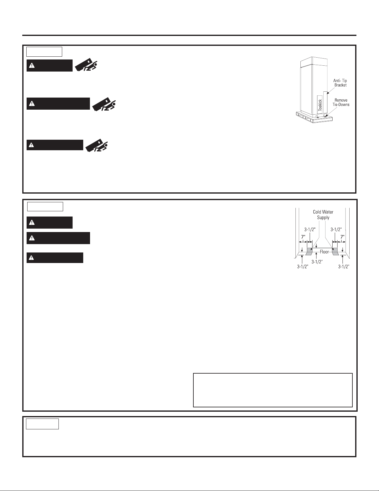
Installation Instructions - Flush Inset Installation for
All-Refrigerator and All-Freezer
STEP 1 REMOVE PACKAGING
WARNING
is much heavier at the top than at the bottom – be careful
when moving. When using a hand truck, handle from side
only.
AVERTISSEMENT
basculement
qu’en bas. Il faut être prudent lors des déplacements. Si un
diable est utilisé, il faut soulever le réfrigérateur sur le côté
seulement.
ADVERTENCIA
El producto es mucho más pesado en su parte superior que en
su parte inferior – tenga cuidado al moverlo. Al usar un carro
manual, sosténgalo de costado únicamente.
Tip Over Hazard. Product
Risque de
Le produit est beaucoup plus lourd en haut
Riesgo de Caída
• Carefully cut banding at the top
and bottom, remove outer carton.
• Slide out back corner posts (2).
• Slide carton off top of cabinet.
NOTE: IT IS NOT NECESSARY TO
LAY CABINET DOWN IN ORDER
TO REMOVE SKID!
NOTE: DO NOT ATTEMPT TO
ROLL UNIT OFF SKID.
• The unit is secured to the skid with 4 slotted tie-down
straps. Remove the four 5/16” bolts from the base
channels in the tie-downs.
• Remove toekick and set aside for final installation.
• Lift the unit off the skid with an appliance dolly. Handle
from the sides.
• Remove the four 7/16” bolts securing the tie-down
brackets to the skid.
STEP 2 INSTALL WATER LINE
WARNING
AVERTISSEMENT
alimentation d’eau potable seulement.
ADVERTENCIA
de agua potable únicamente.
• A cold water supply is required for automaticicemaker
operation. The water pressure must be between 40 and
120 p.s.i.
• Route 1/4” OD copper or SmartConnect™ plastic tubing
between house cold water line and the water connection
location.
• Tubing should be long enough to extend to the front of
the unit. Allow enough tubing to accommodate bend
leading into the water line connection.
NOTE: The only Monogram approved plastic tubing is
supplied in the SmartConnect™ Refrigerator Tubing kits.
Do not use any other plastic water supply line because
the line is under pressure at all times. Other types of
plastic may crack or rupture with age and cause water
damage to your home.
Connect to potable water supply
only.
Raccordez l’appareil à une
Realice la conexión a un suministro
SmartConnect™ Refrigerator Tubing
Kits are available in the following
lengths:
2’ (.6 m) WX08X10002
8’ (2.4 m) WX08X10006
15’ (4.6 m) WX08X10015
25’ (7.6 m) WX08X10025
Shut off the main water supply.
Turn on the nearest faucet long enough to clear the line
of water.
• Install a shut-off valve between the icemaker water
valve and cold water pipe in a basement or cabinet.
The shut-off valve should be located where it will be
easily accessible.
• Turn on the main water supply and flush debris. Run
about a quart of water through the tubing into a bucket.
Shut off water supply at the shut-off valve.
NOTE: Saddle type shut-off valves are included in many
water supply kits. Before purchasing, make sure a saddle
type valve complies with your local plumbing codes.
NOTE: Commonwealth of Massachusetts Plumbing
Codes 248CMR shall be adhered to. Saddle valves
are illegal and use is not permitted in Massachusetts.
Consult with your licensed plumber.
STEP 3 INSTALL SIDE PANELS
Skip this step when not using side panels
If you are using 1/4” (0.63 cm) side panels, they should
be inserted into the case trim.
31-1000454 Rev. 2
Fasten the panels to the unit with stick-on hook and loop
fastener strips before setting unit in place.
51
Page 52

Installation Instructions - Flush Inset Installation for
All-Refrigerator and All-Freezer
STEP 4 INSTALL CASE TRIM
The unit arrives with case trim for standard installation
attached. Flush installation case trim is provided in Kit
ZKFN. Remove the factory installed case trim. Install
new case trim using supplied right hand and left hand
case trim pieces and case trim screws. Attach case
trim to each side of case as shown in illustration using
case trim screws in holes provided down each side of
the case.
STEP 5 INSTALL ANTI-TIP
BRACKET (cont.)
• Cut a 1” x 4” (2.54 x 10.16 cm)
block, 35” (88.9 cm) long.
• Measure and mark under the soffit,
5-1/4” from the front edge of the
cabinet.
• Secure the wood block to under
the soffit. From the bottom of the
block to the finished floor should
measure 84” (213.36 cm). See the
illustration.
• The kit supplied with the unit contains 2 lag bolts and
4 toggles with bolts. The wall bracket will be attached
to the wall in 4 places.
• Measure the opening where the unit is to be installed.
Mark the center with a vertical line.
• Measure up 82” (208.28 cm)from the floor. Mark this
point on the wall.
• Using a level, draw a horizontal line on the wall at this
height.
STEP 5
WARNING
The unit is top-heavy and must be secured to prevent
the possibility of tipping forward.
AVERTISSEMENT
INSTALL ANTI-TIP BRACKET
Tip Over Hazard.
Risque de
basculement
L’appareil ménager est beaucoup plus lourd en haut et il
faut le maintenir en place pour éviter la possibilité de son
basculement vers l’avant.
ADVERTENCIA
La unidad es pesada en su parte superior y se deberá
asegurar a fin de evitar posibles inclinaciones hacia adelante.
Riesgo de Caídas
82”
To Floor
• Locate at least 2 studs on the back wall. Mark these
points on the horizontal line.
• Place the bottom of the wall bracket with tabs on the
horizontal line. Align the center notch on the bracket
with the center line on the wall.
52
31-1000454 Rev. 2
Page 53

Installation Instructions - Flush Inset Installation for
All-Refrigerator and All-Freezer
STEP 5 INSTALL ANTI-TIP BRACKET (cont.)
• The anti-tip wall bracket has a series of holes. Select 2
holes that match with the located studs. Make sure the
holes selected are on the center of the studs. Mark the
wall at these points.
Wall Bracket
Center
Line On Wall
Two Additional
Hole Locations at
Ends of Brackets
Wall Studs
• Mark an additional hole at each end of the bracket.
If one of the studs is closer to the end of the bracket,
mark an additional hole towards the center of the
bracket.
• Drill 1/2” (1.27 cm) holes into the wall board at the
locations marked for the toggles to be mounted (not the
stud markings).
• Drill 3/16” (0.47 cm) holes into wooden studs where
marked. If steel stud construction, drill 1/2” holes into
the studs where marked. You will use 2 toggles with the
metal studs.
• Gently pull back at the ends of the plastic straps to
make the channel rest flush behind the wall.
• Hold the ends of the straps in one hand and slide the
plastic cap along the straps until the flange of the cap is
flush with the wall.
Cap
• Place your thumb between the plastic straps and bend
up and down to snap the straps off at the wall.
Install Screws and Bolts:
• Have someone hold the wall bracket centered in place
with each of the holes aligned with the correct opening
in the bracket and level with the horizontal line.
• Insert the lag screws through the bracket and into the
stud. Tighten with a wrench.
Wood Stud
Lag Screw
Line on Wall
Center
Install Wall Toggles:
The wall toggles and bolts can be ordered as Service Kit
#WR49X10193. Wall toggles are installed in the drywall
and metal studs for stability. Install the wall toggles as
follows:
• Drill 1/2” (1.27 cm) holes at the wall markings made in
the holes at the ends of the wall bracket.
• Hold the metal channel flat against the plastic straps
and slide the channel through the hole.
Plastic Straps
Metal Channel
31-1000454 Rev. 2
Anti-Tip Wall Bracket
• Insert the bolts into the toggle by hand until snug.
Tighten with a wrench.
Drywall or
Steel Stud
Bolt
Wall Toggle
Anti-Tip Wall Bracket
53
Page 54

Installation Instructions - Flush Inset Installation for
All-Refrigerator and All-Freezer
STEP 5 INSTALL ANTI-TIP BRACKET (cont.)
Remove Grilles for Access to Anti-Tip Locking Hooks
Fresh Food Unit
• Open the access door.
• Remove the 4 screws from the grille on the right and 3
screws from the grille on the left.
• Pull the bottom of the grille forward, down and out to
remove.
Screws Screws
Power Cord
Locate the power cord inside the left cavity. If it has not
been adjusted so the plug is easily accessible, do so
now.
Freezer Unit
• Open the access door.
• Remove the 4 screws from the grille on the right and 3
screws from the grille on the left.
• Pull the bottom of the grille forward, down and out to
remove.
Screws Screws
STEP 6 LEVEL UNIT
All models have 4-point leveling. The front is supported
by leveling legs; the rear is supported by adjustable
wheels. Both are accessible from the front of the unit.
• To level the back of the unit, turn the 7/16” hex nut
located above the front wheels. Turn clockwise to raise
or counterclockwise to lower the unit.
• For front leveling, use a 1-1/4” open-end wrench.
Move Unit into Final Position
• Move appliance toward its final installed location. Align
the tabs on the wall bracket with the openings in the
back of the unit.
• The unit has “L” bolts in the upper left and right corners
inside of the access compartment. These bolts will
interlock with the wall bracket and secure the unit
using the washers and hair pin cotters in the hardware
kit once the unit has been leveled and is in the final
position.
• Adjust height of unit to match installation cutout opening
84-1/2” (214.63 cm). The unit should be level and
plumb with cabinetry.
NOTE: Raise appliance until the case top comes in
contact with the 1” (2.54 cm) spacer block mounted to
the underside of the cabinet soffit. Appliance should be
level at fully raised position.
The rear leveling wheels and front leveling legs are
limited to a maximum height adjustment of 1”.(2.54 cm).
If the installation requires more than 84-1/2” (214.63 cm)
height, the installer should elevate the unit on a sheet of
plywood or runners. Cabinetry trim could also be added
across the top of the opening to shorten the opening. If
you attempt to raise the unit more than 1” (2.54 cm), you
will damage the front leveling legs and the rear leveling
wheels.
54
31-1000454 Rev. 2
Page 55

Installation Instructions - Flush Inset Installation for
All-Refrigerator and All-Freezer
STEP 7 SECURE UNIT TO WALL
• The “L” rods can be found in the upper left and right
corners of the unit in the access compartment. Look
through the access compartment to make sure the
rods line up with the anti-tip bracket.
• There are 2 washers and a hair pin cotter per rod.
Remove the washers and hair pin cotter from the end
of the rod.
• Rotate and move
the “L” rod into the
slot in the anti-tip
bracket tab. Once
it is in the slot,
rotate the “L” rod
so the hook portion
is pointing down.
The holes at the
front end of the
rod should be in a
vertical position. Do this to both sides.
• Pull out on the end of the rod to make sure it is
secure in the bracket.
• Locate the hole on the rod that is closest to the unit.
A hair pin cotter will be put through this hole to secure
the rod. If this hole appears to be too far away for a
snug fit against the unit, add the washers one at a
time until the pin will fit tightly into the hole.
• Align the straight section of the pin with the hole
from the underside of the rod. Push the pin up until it
snaps into position. Pliers may be used.
NOTE: The hair pin
cotter must be vertical
when this step is
completed to ensure
the “L” rod is engaged
in the bracket.
• Check the rod for
tightness by pulling
forward. If the rod
moves, remove the
hair pin cotter and
place another washer
on the rod. Reinsert
the pin.
• Replace the grille
panel.
Wall Bracket
“L” Rod
“L” Rod
STEP 8 ADJUST DOOR SWING
NOTE: This appliance has a 3-position door stop.
When space does not allow the door to swing open
fully to 115°, you may change the door swing to a
90° opening. Skip this step if door opening is
satisfactory for your installation situation.
Pin Location
for 90°
Door Swing
Pin Location
as Shipped for
115°
Door Swing
• Open the grille to view the top hinge. Note the door
stop pin locations. The pin is factory-installed in the
115° position.
• Close the door. Use Pliers to unscrew the door stop
and reinstall in the 90 degree position. Close the grill.
WARNING
Improper installation can lead to a finger pinch point
hazard between the side door trim and the cabinets
when operating the door, especially with children.
To minimize this risk you must follow the installation
instructions for cabinet dimensions, trim assembly, and
door stop angle.
AVERTISSEMENT
de doigts
Une installation incorrecte peut poser un risque de
coincement de doigts entre la garniture de porte latérale
et les armoires en actionnant la porte, en particulier pour
les enfants. Pour réduire ce risque, vous devez suivre les
instructions d’installation relatives aux dimensions d’armoire,
au montage des garnitures et à l’angle de l’arrêt de porte.
instructions d’installation relatives aux dimensions d’armoire,
au montage des garnitures et à l’angle de l’arrêt de porte.
Door Trim Pinch Point Hazard
Risque de pincement
31-1000454 Rev. 2
55
Page 56

Installation Instructions - Flush Inset Installation for
All-Refrigerator and All-Freezer
STEP 8 ADJUST DOOR SWING
(Cont.)
ADVERTENCIA
con el Borde de la Puerta
Una instalación inadecuada puede conducir a riesgos de
pellizcos de dedos entre el borde lateral de la puerta y los
gabinetes al utilizar la puerta, especialmente con los niños.
A fin de minimizar este riesgo, usted deberá seguir las
instrucciones de instalación para dimensiones de gabinetes,
ensambles de bordes y esquinas de detención de puertas.
Riesgo de Lastimadura
STEP 9 INSTALL GRILLE PANEL
• Raise the access panel to the stop position.
STEP 10 INSTALL OVERLAY
PANELS
Install door panels:
• Open door to 90°.
• Remove the 12 screws holding the trim, then lift off
the trim. Retain the screws.
• Loosen the screws on the side trim behind the frame.
Remove the bottom trim.
• Slide the panel over the metal backer panel and into
the trim.
• If necessary, tap with a wood block until the panel
slips under the top trim piece.
• Reassemble the bottom trim. Tighten the screws.
Custom Handles
• Custom handles must be used for flush
installation. The handle must be properly secured
to the overlay panel before sliding the panel into
the trim.
• The cabinet
manufacturer
will supply the
custom handle and
hardware.
• Slide assembled door
panel into the trim.
• Reinstall trim by
securing with all 12
screws retained in
previous steps.
56
31-1000454 Rev. 2
Page 57

Installation Instructions - Flush Inset Installation for
All-Refrigerator and All-Freezer
STEP 11
CONNECT WATER SUPPLY
(FREEZER MODELS ONLY)
WARNING
AVERTISSEMENT
alimentation d’eau potable seulement.
ADVERTENCIA
suministro de agua potable únicamente.
• Locate and bring the tubing to the front of the cabinet.
• Turn the water on to flush debris from the line. Run
about a quart of water through the tubing into a
bucket, then shut off the water.
Copper Tubing:
• Slip a 1/4” nut and ferrule (provided) over both ends
of the copper tubing. Insert the tube into the union
fitting on the unit and tighten the nut to the union.
• Turn on the water to check for leaks.
SmartConnect™ Tubing:
NOTE: The only Monogram-approved plastic tubing is
supplied in the SmartConnect™ Refrigerator Tubing kits.
Do not use any other plastic water supply line because
the line is under pressure at all times. Other types of
plastic may crack or rupture with age and cause water
damage to your home.
• Insert the molded end of the tubing into the appliance
or freezer connection. Tighten the compression nut
until it is just hand-tight.
• Tighten one additional turn with a wrench.
Overtightening can cause leaks!
• Turn on the water to check for leaks.
NOTE: Make sure excess tubing length does not
interfere with the toekick installation.
Connect to potable water supply
only.
Raccordez l’appareil à une
Realice la conexión a un
House
Water Supply
Freezer
Water Supply
STEP 12 CONNECT POWER
• Check to be sure the power cord is plugged into the
receptacle.
Electrical Outlet
• Check to make sure power to refrigerator is on by
opening refrigerator door to see if interior lights are
on.
• The temperature controls are preset at 37°F
(-13.89°C) for the fresh food section and 0°F
(-17.78°C) for the freezer.
• Allow 24 hours to stabilize before making
adjustments.
STEP 13
START ICEMAKER
(FREEZER MODELS ONLY)
CAUTION
the ejector mechanism, or with the heating element
(located on the bottom of the icemaker) that releases
the cubes. Do not place fingers or hands on the
automatic ice making mechanism while the freezer is
plugged in.
ATTENTION
mobiles du mécanisme d’éjection, ou l’élément chauffant
(situé dans le bas de la machine à glaçons) qui libère les
glaçons. Ne placez pas les doigts ou les mains sur le
mécanisme de production de glace automatique lorsque le
congélateur est branché dans la prise électrique.
PRECAUCIÓN
movimiento del mecanismo expulsor o con el elemento de
calefacción (ubicado en la parte inferior de la máquina de
hielos) que expulsa los cubos. No coloque los dedos ni las
manos en el mecanismo de la máquina de hielos automática
mientras el freezer se encuentre enchufado.
Avoid contact with the moving parts of
Évitez tout contact avec les pièces
Evite el contacto con las partes en
Icemaker
31-1000454 Rev. 2
Feeler Arm
• The icemaker will begin operation automatically.
• Be sure nothing interferes with the sweep of the feeler
arm.
• Discard the first full bucket of ice cubes.
• To turn the icemaker off, see Standard Installation
57
Page 58

Installation Instructions - Flush Inset Installation for
All-Refrigerator and All-Freezer
STEP 14 INSTALL TOEKICK
• A custom toekick can be installed to match or
complement the surrounding cabinetry.
IMPORTANT: The custom toekick must NOT cover the
horizontal vent slots of the factory toe kick provided with
the original refrigerator and should be 1-5/8" longer on
each side. Final height should be cut once the unit is
leveled.
• Install the toekick assembly with the 2 screws
provided, adjust to the desired height and tighten
screws.
58
31-1000454 Rev. 2
Page 59

Instructions for Side-by-Side
Refrigerator Installation
31-1000454 Rev. 2
59
Page 60

Design Guide - Flush Inset Installation for
Side-by-Side Refrigerator
THE INSTALLATION SPACE
36" Models 12"
42" Models 19"
48" Models 22-1/4"
*Finished Width
6"
85" max
Finished
Opening
*Finished cutout width must be:
39” (99.06 cm) for 36” models
45” (114.3 cm) for 42” models
51” (129.54 cm) for 48” models
Water And Electrical Locations
The opening must be prepared with the electrical and
the cold water supply located as shown.
The Cutout Depth Must Be 26-3/16” (66.99 cm)
Wooden cleats are required for flush installation. See
Side Cleats on page 65. If 3/4” (1.91 cm) Overlay
panels w/ 90 degree door swing are to be used then
cutout depth must be 26-1/4” (66.68 cm)
Additional Specifications
• A 115 volt 60Hz., 15 or 20 amp power supply is
required. An individual properly grounded branch
circuit or circuit breaker is recommended. Install
a properly grounded 3-prong electrical receptacle
recessed into the back wall. Electrical must be located
on the rear wall as shown.
• The water line can enter the opening through the
floor or back wall. The water line should be 1/4” O.D.
copper tubing or SmartConnect™ kit between the cold
water line and water connection location, long enough
to extend to the front of the refrigerator. Installation of
an easily accessible shut-off valve in the water line is
required.
Electrical
Area
26-3/16"
7"
Water Supply
3 1/2"
5"
75" From Floor
to Bottom
of Electrical
Area
7"
3 1/2"
DIMENSIONS AND CLEARANCES
35-1/2", 41-1/2",
or 47-1/2"
Case Width
*84-1/2" Max
*83-1/2" Min
at Rear
36", 42" or 48"
Frame to Frame
Depth Including Handles 26-7/8"
Product Clearances
These refrigerators are equipped with a 3-position door
stop. The factory-set 115° door swing can be adjusted
to 90° if clearance to adjacent cabinets or walls is
restricted. Only standard installation can be adjusted to
130°.
Allow minimum clearances for the freezer door
115° Door Swing
A
Models A B C
36” 13”
(33.02 cm) 15” (38.1 cm) 20-5/8” (52.39 cm)
42” 13” (33.02 cm) 19” (48.26 cm) 26-5/8” (67.63 cm)
48” 15” (38.1 cm) 20” (50.8 cm) 28-5/8” (72.71 cm)
(Dimension A) and fresh food door (Dimension B) for a
full 115° door swing and to allow for pan removal.
25-3/8" Framed Models
*84"
From
Floor
B
* Shipping height.
The refrigerator can
be adjusted to fit
into a cutout that is
85” (215.9 cm) in
height. Use leveling
legs and wheels
for a maximum 1”
(2.54 cm) height
adjustment.
90° Door Swing
23-7/8"
Behind
Frame
C
*Min. Distance
to Wall
*4-5/8” Stainless and
Trimmed Models.
5” Pro Series
For a 90° door swing, allow 4” (10.16 cm) min.
clearance to a wall, for framed and stainless steel
models. Allow 5” (12.7 cm) min. clearance for
professional series models. If the 90° door stop position
is used, pan access is maintained, but pan removal is
restricted.
60
31-1000454 Rev. 2
Page 61

Design Guide - Flush Inset Installation for
Side-by-Side Refrigerator
CUSTOMIZATION BASICS:
These refrigerators are designed to be customized with decorative panels. Field installed custom door and grille
panels are required.
CUSTOM HANDLE DESIGN GUIDE
Custom handles must be used for flush installation. For custom handle installation,
counterbore holes in rear of decorative panels must ensure 1/2” (1.27 cm) material
thickness remains for handle support.
NOTE: The counterbore must not exceed 1” (2.54 cm)in diameter.
Minimum distance from handle side edge to handle center should be 1-1/4” (3.18 cm) as
shown.
1/2”
1/4”
3/4”
REFRIGERATOR LOCATION
• Do not install the refrigerator where the temperature
will go below 55°F (13°C). It will not run often
enough to maintain proper temperatures.
• Do not install the refrigerator where temperatures will
go above 100°F (37°C). It will not perform properly.
• Do not install the refrigerator in a location exposed to
water (rain, etc.) or direct sunlight.
• Install it on a floor strong enough to support it fully
loaded.
7/8"
0.85"
1/2"
SIDE PANELS
Side panels must be used
whenever the sides of
the refrigerator will be
exposed. The 1/4”
(0.63 cm) side panels will
slip into the side case
trim. Secure the panels
to the refrigerator with
stick-on hook and loop
fastener strips. Order
the side panels from the
cabinet manufacturer.
• Cut a notch in the top
front corner as shown
to allow clearance for
corner keys in the front
side trim.
1-1/4”1-1/4”
24"
3/16"
1-7/8"
*84"
*3" to 4"
2-9/16"
* Depending on installation height.
31-1000454 Rev. 2
61
Page 62

Design Guide - Flush Inset Installation for
1/2"
Overlay
Panel
1/4"
Backer
Panel
Door
.10"
Spacer
D
Side-by-Side Refrigerator
1/2” (1.27 cm) OVERLAY PANEL DIMENSIONS
For a more custom appearance, overlay panels may be installed on trimmed models. The
overlay panel must be secured to a 1/4” (0.63 cm) thick backer panel which slides into the
trim. A spacer panel 0.10” (0.25 cm) thick must be placed between the overlay and backer
panel.
Assemble the panels with glue and screws:
• Center the spacer panel on the backer panel, left to right and top to bottom. Secure the
panels with glue.
• Refer to the following chart for locating the backer panel to the overlay panel. Secure the
overlay panel to the backer panel with glue and screws. Screws must be countersunk into
the backer panel.
Hinge Side
C
Freezer
Back
Backer with
Overlay Panel
Assembly
C
Fresh Food
Back
A B
SxS Fresh Food 2-1/16” 1/4” 1/8” 1/8”
D
D
SxS Freezer 2-1/16” 1/4” 1/8” 1/8”
SxS Grille 2-1/16” 2-1/16” 1-15/32”* 7/32”
A
AB
B
IMPORTANT NOTE – DISPENSER MODELS
This kit is supplied with 2 dispenser trims. The flush
installation trim is designed to fit a total panel thickness
of 0.85” (2.16 cm) or 0.75” (1.91 cm).
• If the panel is less than 0.75” (1.91 cm) a noticeable
gap may be created around the dispenser trim.
• If the panel is more than 0.85” (2.16 cm) the dispenser
trim cannot be secured to the door.
.250” + .10” + .50” = .85”
0.63 + 0.25 + 1.27 = 2.16 cm
Total Panel Thickness
Grille Back
C
AB CD
*2” for 36” models
• The overlay panel must be constructed according to
the specifications shown to achieve the correct total
thickness.
• Cut the dispenser opening after the backer, spacer
and overlay panels have been assembled.
Panel Dimensions
36” Side-by-Side Fresh Food Freezer Grille Dispenser Cutout Position
1/4” Backer Panel 68-3/8” x 18-9/16” 68-3/8” x 14-9/16” 33-7/8” x 9”
.10” Spacer Panel 67” x 17-9/16” 67” x 13-9/16” 33” x 8-3/8”
EF
1/2” Overlay Panel 68-5/8” x 20-7/8” 68-5/8” x 16-7/8” 38” x 11-3/16” 34-9/32” 3-15/16”
13-5/16”
42” Side-by-Side Fresh Food Freezer Grille Dispenser Cutout Position
1/4” Backer Panel 68-3/8”x 24-9/16” 68-3/8” x 14-9/16” 39-7/8” x 9-1/2”
.10” Spacer Panel 67” x 23-9/16” 67” x 13-9/16” 39” x 8-5/8”
EF
1/2” Overlay Panel 68-5/8” x 26-7/8” 68-5/8” x 16-7/8” 44” x 11-3/16” 34-9/32” 3-15/16”
F
E
48” Side-by-Side Fresh Food Freezer Grille Dispenser Cutout Position
1/4” Backer Panel 68-3/8” x 26-9/16” 68-3/8” x 18-9/16” 45-7/8” x 9-1/2”
.10” Spacer Panel 67” x 25-9/16” 67” x 17-9/16” 45” x 8-5/8”
EF
1/2” Overlay Panel 68-5/8” x 28-7/8” 68-5/8” x 20-7/8” 50” x 11-3/16” 34-9/32” 5-15/16”
11”
IMPORTANT NOTE: Maximum total weight for the assembled panels:
• Fresh food door panel – 75 lbs.(34 kg) • Freezer door panel – 53 lbs.(24 kg) • Grille Panel – 18 lbs. (8.16 kg)
62
31-1000454 Rev. 2
Page 63

Design Guide - Flush Inset Installation for
Side-by-Side Refrigerator
3/4” (1.91 cm) RAISED PANEL DIMENSIONS
For a more custom appearance raised panels may be installed on trimmed models.
The panels must be 3/4” (1.91 cm) thick at and routed per the instructions below in
order to guarantee proper operation
IMPORTANT NOTE – DISPENSER MODELS
This kit is supplied with 2 dispenser trims. The overlay dispenser trim is designed to
fit a total panel thickness of 0.85” (2.16 cm) or 0.75” (1.91 cm).
• If the panel is less than 0.75” (1.91 cm) a noticeable gap may be created around
the dispenser trim.
• If the panel is more than 0.85” (2.16 cm) the dispenser trim cannot be secured to
the door.
• The overlay panel must be constructed according to the specifications shown to
achieve the correct total thickness.
Panel Dimensions
Door
3/4"
Raised
Panel
13-5/16”
F
11”
WARNING
36” Side-by-Side Fresh Food Freezer Grille Dispenser Cutout Position
3/4” Raised Panel 68-5/8” x 20-7/8” 68-5/8” x 16-7/8” 38” x 11-3/16” 34-9/32” 3-15/16”
42” Side-by-Side Fresh Food Freezer Grille Dispenser Cutout Position
3/4” Raised Panel 68-5/8” x 26-7/8” 68-5/8” x 16-7/8” 44” x 11-3/16” 34-9/32” 3-15/16”
48” Side-by-Side Fresh Food Freezer Grille Dispenser Cutout Position
E
3/4” Raised Panel 68-5/8” x 28-7/8” 68-5/8” x 20-7/8” 50” x 11-3/16” 34-9/32” 5-15/16”
IMPORTANT NOTE: Maximum total weight for the assembled panels:
• Fresh food door panel – 75 lbs. (34 kg)
• Freezer door panel – 53 lbs. (24 kg)
• Grille Panel – 18 lbs. (3.16 kg)
Door Trim Pinch Point Hazard
E F
E F
E F
Improper installation can lead to a finger pinch point hazard between the side door trim and the cabinets when
operating the door, especially with children. To minimize this risk you must follow the installation instructions for
cabinet dimensions, trim assembly, and door stop angle.
AVERTISSEMENT
Une installation incorrecte représente un risque de pincement pour les doigts entre le côté de la garniture de porte et les armoires
lors de l’ouverture ou de la fermeture de la porte, spécialement pour les enfants. Pour réduire ce risque, vous devez suivre les
instructions d’installation selon les dimensions des armoires, l’assemblage de garniture et l’angle de butée de la porte.
ADVERTENCIA
Una instalación inadecuada podrá conducir a riesgos de pellizcos de dedos entre el marco lateral de la puerta y los gabinetes al
utilizar la puerta, especialmente con los niños. A fin de minimizar este riesgo, usted deberá seguir las instrucciones de instalación
para dimensiones de gabinetes, ensambles de marcos y ángulos de detención de puertas.
31-1000454 Rev. 2
Risque de pincement de la garniture de porte
Riesgo de Pellizcos con el Marco de la Puerta
63
Page 64

Design Guide - Flush Inset Installation for
Side-by-Side Refrigerator
3/4” (1.91 cm) RAISED DOOR PANEL ROUTING
For 3/4” (1.91 cm) raised door panel, routing is required. The router depth is 1/4” (0.63 cm) all the way around the
panel back. Additional panel width reductions are required per the diagrams below. This will create a “picture frame”
routing that will slide onto the attached door trim.
Back
TOP DETAIL TOP
3/4”
11/32”
1/4”
Front
3/32”
DETAIL BOTTOM
1/4”
11/32”
NOTE: Routed areas should be
finished as they may be visible
when assembled.
Front
Back
CORNER VIEW SHOWING
“PICTURE FRAME” ROUTING
DETAIL HINGE
BOTTOM
3/4” PANEL SIDE VIEW
(AFTER ROUTING)
SIDE
ROUTER DEPTH 1/4”
2-1/16”
Front
HINGE
SIDE
Back
3/4” PANEL BOTTOM VIEW
(AFTER ROUTING)
DETAIL HANDL
3/16”
E
SIDE
HANDLE
SIDE
NOTE: For panels constructed with rails and stiles (5-panel), the minimum width is 3” (7.62 cm) for rails and 4” (10.16 cm)
for stiles.
64
31-1000454 Rev. 2
Page 65

Design Guide - Flush Inset Installation for
Side-by-Side Refrigerator
3/4” (1.91 cm) RAISED GRILLE PANEL ROUTING
For 3/4” (1.91 cm) raised grille panel, routing is required. The router depth is 1/4” (0.63 cm) all the way around the
panel back. Additional panel width reductions are required per the diagrams below. This will create a “picture frame”
routing that will slide onto the attached grille trim.
DETAIL TOP
TOP
NOTE: Routed areas should be
finished as they may be visible
when assembled.
Front
Back
Back
Front
1-1/2”
2” for 36”
models
ROUTER DEPTH 1/4”
BOTTOM
3/4” PANEL SIDE VIEW
(AFTER ROUTING)
LEFT
SIDE
DETAIL
LEFT SIDE
CORNER VIEW SHOWING
“PICTURE FRAME” ROUTING
3/16”
DETAIL BOTTOM
DETAIL RIGHT
SIDE
ROUTER DEPTH 1/4” ROUTER DEPTH 1/4”
2-1/16” 2-1/16”
Front
RIGHT
SIDE
Back
3/4” PANEL BOTTOM VIEW
(AFTER ROUTING)
NOTE: For panels constructed with rails and stiles (5-panel), the minimum width is 3” (7.62 cm) for rails and 4” (10.16 cm)
for stiles.
31-1000454 Rev. 2
65
Page 66

Design Guide - Flush Inset Installation for
Side-by-Side Refrigerator
DISPENSER TRIM FIT EXAMPLES:
(NOT TO SCALE)
CUSTOM PANEL
• The dispenser trim fits over the custom
panel and snaps into the freezer door.
Custom Panel
SIDE CLEATS
Wood cleats are required to be installed vertically down
both sides of the cabinet opening to provide depth stop
for the refrigerator when installed into the opening.
The cleat should be installed per the diagrams below
based on the type of panel being used.
TOP VIEW
Finished
Cleat
FREEZER DOOR
Ice / Water Dispenser
3/4”Overlay Dispenser Trim
5-1/4”
Finished
Cleat
5-3/8”
DOOR
3/4” Panel
Case Trim
TOP VIEW
DOOR
1/2” Panel
Case Trim
1/2”
1/2”
66
31-1000454 Rev. 2
Page 67

Installation Instructions - Flush Inset Installation for
Side-by-Side Refrigerator
TOOLS AND MATERIALS REQUIRED
• Tinsnips to cut banding
• Stepladder
• 1” Bit extension
• Tape measure
• Gloves
• 1/4” Drywall screws
• 5-Gal. Bucket with cover
• 6” Spirit level
• Appliance hand truck
• Tubing cutter
• 7/16” open-end wrench
• #2 Phillips screwdriver
• Drill and appropriate bits
• 5/16”, 7/16” socket
• Safety glasses
• 1-1/8” open end wrench
• Pliers
• 1/4”, 5/16” Combo Rachet
• 35” long 2x4 for Anti-Tip support
• 1/4” copper water line tubing or SmartConnect™
Refrigerator Tubing kits
• Water shut-off valve
• Custom panels for doors and grille panel
• Screws to secure refrigerator to cabinetry
• Stick-on hook and loop fastener strips for 1/4” side
panels
HARDWARE SUPPLIED WITH UNIT
• Water filter bypass plug
• 1/4” nut and ferrule
FLOORING
For proper installation, this refrigerator must be placed
on a level surface of hard material that is at the same
height as the rest of the flooring. This surface should
be strong enough to support a fully loaded refrigerator,
or approximately 1,500 lbs.(680.39 kg).
NOTE: Protect the finish of the flooring. Cut a large
section of the cardboard carton and place under the
refrigerator where you are working.
GROUNDING THE REFRIGERATOR
WARNING
Failure to follow these instructions can result in death,
fire, or electrical shock.
The power cord of this appliance is equipped with a
3-prong (grounding) plug which mates with a standard
3-prong (grounding) wall receptacle to minimize the
possibility of electric shock hazard from this appliance.
Have the wall outlet and circuit checked by a qualified
electrician to make sure the outlet is properly grounded.
Where a standard 2-prong wall outlet is encountered, it
is your personal responsibility and obligation to have it
replaced with a properly grounded 3-prong wall outlet.
DO NOT, UNDER ANY CIRCUMSTANCES, CUT OR
REMOVE THE THIRD (GROUND) PRONG FROM
THE POWER CORD.
DO NOT USE AN ADAPTER PLUG TO CONNECT
THE REFRIGERATOR TO A
2-PRONG OUTLET.
DO NOT USE AN EXTENSION
CORD WITH THIS APPLIANCE.
Electrical Shock Hazard.
MISE À LA TERRE DU RÉFRIGÉRATEUR
AVERTISSEMENT
électrique.
Le non-respect de ces instructions peut entraîner des
risques d’incendies, des chocs électriques ou la mort.
Le cordon d’alimentation de cet appareil est équipé
d’une fiche à trois broches (pour une mise à la terre)
qui s’adapte à la prise de courant standard à 3 broches
(pour une mise à la terre) pour minimiser les risques de
chocs électriques par cet appareil.
Faites vérifier la prise murale et le circuit électrique par
un électricien qualifié pour s’assurer que le système est
correctement mis à la terre.
Dans le cas d’une prise biphasée, l’installateur a la
responsabilité et l’obligation de la remplacer par une
prise triphasée correctement mise à la terre.
NE COUPEZ PAS OU N’ENLEVEZ PAS, SOUS
AUCUN PRÉTEXTE, LA TROISIÈME BROCHE DE
MISE À LA TERRE DU CORDON
D’ALIMENTATION.
N’UTILISEZ PAS D’ADAPTATEUR
POUR BRANCHER LE
RÉFRIGÉRATEUR À UNE PRISE
BIPHASÉE.
N’UTILISEZ PAS DE RALLONGE AVEC CET
APPAREIL.
Risque de choc
31-1000454 Rev. 2
67
Page 68

Installation Instructions - Flush Inset Installation for
Side-by-Side Refrigerator
CONEXIÓN A TIERRA DEL
REFRIGERADOR
ADVERTENCIA
Eléctrica
Si no se siguen estas instrucciones, se podrá producir la
muerte, incendios o descargas eléctricas.
El cable de corriente de este electrodoméstico cuenta con
un enchufe de 3 cables (conexión a tierra) que se conecta a
un tomacorriente de pared estándar de 3 cables (conexión
a tierra) para minimizar el riesgo de posibles descargas
eléctricas por parte del mismo.
Contrate a un electricista calificado para que controle el
tomacorriente y el circuito eléctrico, a fin de asegurar que el
enchufe esté correctamente conectado a tierra.
En caso de contar con un tomacorriente de pared de 2
cables, es su responsabilidad y obligación reemplazarlo
por un tomacorriente de pared de 3 cables correctamente
conectado a tierra.
NUNCA, BAJO NINGUNA CIRCUNSTANCIA,
CORTE NI ELIMINE EL TERCER CABLE
(TIERRA) DEL CABLE DE CORRIENTE.
NO USE UN ENCHUFE ADAPTADOR PARA
CONECTAR EL REFRIGERADOR A UN
TOMACORRIENTE DE 2 PATAS.
NO USE UN PROLONGADOR CON ESTE
ELECTRODOMÉSTICO.
Riesgo de Descarga
STEP 1 REMOVE PACKAGING
WARNING
The refrigerator is much heavier at the top than at the
bottom—be careful when moving. When using a hand
truck, handle from the side only.
AVERTISSEMENT
basculement Le réfrigérateur est beaucoup plus lourd en
haut qu’en bas. Il faut être prudent lors des déplacements. Si
un diable est utilisé, il faut soulever le réfrigérateur sur le côté
seulement.
ADVERTENCIA
El refrigerador es mucho más pesado en su parte superior
que en su parte inferior – tenga cuidado al moverlo. Al usar
un carro manual, sosténgalo de costado únicamente.
• Carefully cut banding at the top and bottom,
remove the outer carton.
• Slide out the back corner posts (2).
• Slide the carton off the top of the cabinet.
NOTE: IT IS NOT NECESSARY TO LAY THE
CABINET DOWN IN ORDER TO REMOVE THE SKID!
Tip Over Hazard.
Risque de
Riesgo de Caídas
STEP 1 REMOVE PACKAGING (Cont.)
• The unit is secured to the
skid with 4 slotted tie-down
straps. Remove the six 7/16”
bolts from the base channels
in the tie-downs.
• Remove the six 7/16” bolts
securing the straps to the
skid.
NOTE: DO NOT ATTEMPT
TO ROLL UNIT OFF SKID.
• The support blocks on the
bottom of the refrigeration
case must be removed before the refrigerator is taken
off the skid or damage will occur. Carefully tilt the
refrigerator and slide the blocks out from beneath.
• Remove the toekick and set aside for final installation.
• Lift the refrigerator off the skid with an appliance dolly.
Handle from the sides.
Toekick
Tie Downs
Remove
STEP 2 MOVE THE REFRIGERATOR
INTO THE HOUSE
• Re-use the corner posts from the packaging to protect
stainless steel models. Run the appliance dolly straps
over the posts and under the handles.
• Leave the protective film on the refrigerator until
installation is complete. IMPORTANT: Never lift the
refrigerator by the handle or push against the grille
panel; this could cause damage or misalignment.
• Avoid laying the unit on its back or side to prevent
sealed system restrictions.
STEP 3 INSTALL WATER LINE
WARNING
AVERTISSEMENT
alimentation d’eau potable seulement.
ADVERTENCIA
suministro de agua potable únicamente.
• A cold water supply is required for automatic icemaker
operation. The water pressure must be between 40
and 120 p.s.i. (275-827 kPa).
• Route 1/4” OD copper or SmartConnect™ plastic
tubing between house cold water line and the water
connection location.
Connect to potable water supply
only.
Raccordez l’appareil à une
Realice la conexión a un
68
31-1000454 Rev. 2
Page 69

Installation Instructions - Flush Inset Installation for
Side-by-Side Refrigerator
STEP 3 INSTALL WATER LINE (Cont.)
• The tubing should be long enough to extend to the
front of the refrigerator. Allow enough tubing to
accommodate the bend leading into the water line
connection.
Floor
Cold Water Line
NOTE: The only Monogram approved plastic tubing is
supplied in the SmartConnect™ Refrigerator Tubing kits.
Do not use any other plastic water supply line because
the line is under pressure at all times. Other types of
plastic may crack or rupture with age and cause water
damage to your home.
SmartConnect™ Refrigerator Tubing Kits are available
in the following lengths:
2’ (.6 m) WX08X10002
8’ (2.4 m) WX08X10006
15’ (4.6 m) WX08X10015
25’ (7.6 m) WX08X10025
Shut off the main water supply.
Turn on the nearest faucet long enough to clear the
line of water.
• Install a shut-off valve between the icemaker water
valve and cold water pipe in a basement or cabinet.
The shut-off valve should be located where it will be
easily accessible.
• Turn on the main water supply and flush debris.
Run about a quart of water through the tubing into a
bucket. Shut off the water supply at the shut-off valve.
NOTE: Saddle type shut-off valves are included in
many water supply kits. Before purchasing, make sure
a saddle type valve complies with your local plumbing
codes.
NOTE: Commonwealth of Massachusetts Plumbing
Codes 248CMR shall be adhered to. Saddle valves
are illegal and use is not permitted in Massachusetts.
Consult with your licensed plumber.
STEP 4 INSTALLATION WITH
HOUSEHOLD WATER
FILTRATION SYSTEM
Skip this step if you do not have a household water
filtration system
If the water supply to the refrigerator is from any
household water filtration system, the filter cartridge
should be removed. For better ice and water
performance, remove the filter and install the filter
bypass plug.
Rotate Counterclockwise
to Remove
Filter Bypass
Plug
STEP 5 INSTALL SIDE PANELS
Skip this step when not using side panels.
If you are using 1/4” (0.63 cm) side panels, they should
be inserted into the case trim. Fasten the panels to the
refrigerator with stick-on hook and loop fastener strips
before setting the refrigerator in place.
STEP 6 INSTALL CASE TRIM
The unit arrives with case trim for standard installation
attached. Flush installation case trim is provided in Kit
ZKFN. Remove the three pieces of factory installed
case trim (both sides and top). Install new case trim
using supplied right hand and left hand case trim
pieces and case trim screws. A top piece of case trim
is not required for flush
installation. Attach case
trim to each side of case
as shown in illustration
using case trim screws
in holes provided down
each side of the case.
31-1000454 Rev. 2
69
Page 70

Installation Instructions - Flush Inset Installation for
Side-by-Side Refrigerator
STEP 7 ANTI-TIP PROCEDURE
WARNING
These refrigerators are top heavy, especially with any
doors open, and must be secured to prevent tipping
forward which could result in death or serious injury.
Read and follow the entire installation instructions for
securing the refrigerator with the anti-tip system.
AVERTISSEMENT
basculement
Ces réfrigérateurs présentent une partie supérieure lourde,
en particulier avec une porte ouverte; ils doivent donc être
fixés pour prévenir le basculement vers l’avant et le risque
concomitant de blessure grave ou fatale. Lisez et suivez
les instructions d’installation complètes pour l’installation du
système anti-basculement.
ADVERTENCIA
Estos refrigeradores son inestables, especialmente
cuando una puerta se encuentre abierta, y deberán estar
asegurados a fin de evitar caídas hacia adelante que
podrían resultar en la muerte o en lesiones graves. Lea y
siga las instrucciones de instalación en su totalidad para
asegurar el refrigerador con el sistema anti volcaduras.
Tip Over Hazard.
Risque de
Riesgo de Caídas
STEP 7 ANTI-TIP PROCEDURE (Cont.)
• Once the refrigerator is pushed into the opening,
use leveling legs to raise the refrigerator until it rests
against the block installed at the top of the opening.
We recommend units for flush installation be
installed under a soffit. If this is not possible,
follow these instructions using the mounting
brackets.
• Cut a 2” x 4” block, 35” (88.9 cm) long and secure the
block to the mounting brackets provided using #12 or
#14 wood screws.
• Secure the bracket with wood block to the back
wall so that it is 84-1/2” (214.63 cm) from the
finished floor. Use #12 or #14 wood screws. See the
illustration.
• The screws must
penetrate at least one
inch into the vertical
wall studs.
• If metal wall studs then
use self-tapping sheet
metal screws in place
of the wood screws to
secure the block and
brackets to the wall.
• Cut a 1” x 4” block, 35” (88.9 cm)
long.
Block
Soffit
• Measure and mark under the soffit,
5-1/4” (13.34 cm) from the front
edge of the cabinet.
• Secure the wood block under the
soffit. From the bottom of the block
to the finished floor should measure
84-1/2”
From
Floor to
Bottom
of Wood
Block
84-1/2” (214.63 cm). See the
illustration.
Side View
Connect Power Cord:
• Before pushing the refrigerator into the opening, plug
the power cord into the receptacle. The water filter
guard will need to be removed for access (some
models). Remove the 3 screws holding it in place. If
access is still too tight, remove the 2 screws holding
the water filter bracket and move aside. Open the
grille panel and reach into the opening at the back
to grasp the power cord. Pull the power cord into the
opening as you push the refrigerator back. Secure the
bracket and guard with the original screws.
• Gently push refrigerator into the opening with hands
against front corners.
STEP 8 LEVEL REFRIGERATOR
All models have 4-point leveling. The front is supported
by leveling legs, the rear is supported by adjustable
wheels. Both are accessible from the front of the
refrigerator.
• To level the back of the
refrigerator, turn the 7/16”
hex nut located above
the front wheels. Turn
clockwise to raise or
counterclockwise to lower
the refrigerator.
• For front leveling, use a
1-1/4” open-end wrench.
• Adjust height of refrigerator to match installation
cutout opening 84-1/2” (214.63 cm). The refrigerator
should be level and plumb with cabinetry.
NOTICE: The rear leveling wheels and front leveling
legs are limited to a maximum height adjustment of 1”
(2.54 cm). If the installation requires more than 84-1/2”
(214.63 cm) height, the installer should elevate the
refrigerator on a sheet of plywood or runners. Cabinetry
trim could also be added across the top of the opening
to shorten the opening. If you attempt to raise
the refrigerator more than 1” (2.54 cm), you will
damage the front leveling legs and the rear leveling
wheels. Make adjustments in small increments.
70
31-1000454 Rev. 2
Page 71

Installation Instructions - Flush Inset Installation for
Side-by-Side Refrigerator
STEP 9 ADJUST DOOR SWING
NOTE: This refrigerator has a 3-position door stop.
When space does not allow the door to swing open
fully to 115°, you may change the door swing to a
90° opening. A 130° door swing option is available
for standard installation only. Skip this step if door
opening is satisfactory for your installation
situation.
• Open the door to view the bottom hinge. Note the
door stop pin locations. The pin is factory installed in
the 115° position.
• Close the door. From below, use pliers to unscrew the
door stop and reinstall into the 90° position.
WARNING
Hazard
Improper installation can lead to a finger pinch point
hazard between the side door trim and the cabinets
when operating the door, especially with children.
To minimize this risk you must follow the installation
instructions for cabinet dimensions, trim assembly, and
door stop angle.
AVERTISSEMENT
de la garniture de porte
Une installation incorrecte représente un risque de pincement
pour les doigts entre le côté de la garniture de porte et les
armoires lors de l’ouverture ou de la fermeture de la porte,
spécialement pour les enfants. Pour réduire ce risque,
vous devez suivre les instructions d’installation selon les
dimensions des armoires, l’assemblage de garniture et l’angle
de butée de la porte.
ADVERTENCIA
Pellizcos con el Marco de la Puerta
Una instalación inadecuada podrá conducir a riesgos de
pellizcos de dedos entre el marco lateral de la puerta y los
gabinetes al utilizar la puerta, especialmente con los niños.
A fin de minimizar este riesgo, usted deberá seguir las
instrucciones de instalación para dimensiones de gabinetes,
ensambles de marcos y ángulos de detención de puertas.
Door Trim Pinch Point
Risque de pincement
Riesgo de
STEP 10 INSTALL GRILLE PANEL
To insert the framed or overlay panel into the grille:
• Raise the grille panel to the stop position.
Loosen
Side
Trim
Screw
Adjust Nut Below
Spring to Accommodate
Panel Weight
• Loosen the screws on the side trim behind the frame.
Remove the bottom trim.
CAUTION
The metal panel may be slippery. Grip the metal
panel firmly so the panel does not slip out of the
frame and cause personal injury or damage to the
frame.
ATTENTION
AUX ARÊTES VIVES
Le panneau en métal peut bêtre glissant. Tenir
fermement le panneau en métal, de manière à ce
que le panneau ne glisse pas en dehors du cadre en
provoquant des blessures corporelles ou des dommages
au cadre.
PRECAUCIÓN
Es posible que el panel metálico esté resbaladizo. Tome
el panel metálico de manera firme, de modo que no se
deslice fuera del marco y ocasione lesiones personales o
daños sobre el marco.
• Slide the panel over the metal backer panel and into
the trim.
• If necessary, tap with a wood block until the panel
slips under the top trim piece.
• Reassemble the bottom trim. Tighten the screws.
• Adjust the hinge spring to accommodate the panel
weight, if necessary.
SHARP EDGE HAZARD
RISQUE DE COUPURE : ATTENTION
RIESGO DE EXTREMO FILOSO
Loosen
Side
Trim
Screw
31-1000454 Rev. 2
71
Page 72

Installation Instructions - Flush Inset Installation for
Side-by-Side Refrigerator
STEP 11 INSTALL OVERLAY PANELS
Install door panels:
• Open door to 90°.
• Remove the 12 screws holding the door trim on the
handle side, then lift off the trim. Retain the screws.
• Slide the overlay panel into the door trim.
• Custom handles must be used with flush inset.
Make sure handles are attached before installing
panels.
Dispenser Models Only:
• IMPORTANT: The dispenser controls protrude
beyond the face of the freezer door. To avoid damage
to the dispenser, the trim at the top of the door should
be removed.
• Remove the screws holding the top trim in place.
• Place the assembled freezer panel into the bottom
channel and slide into the hinge side trim.
• Reinstall the top trim piece with all of the original
screws.
All Models:
• There are two sets of holes in the door trim. Replace
door trim by installing all of the screws in the two sets
of screw holes.
• Follow the same procedures to install the opposite
panel.
Door
Trim
Refrigerator
Door
Top Trim
Use front and rear
holes to install all of
the original screws
and secure trim
72
31-1000454 Rev. 2
Page 73

Installation Instructions - Flush Inset Installation for
Side-by-Side Refrigerator
STEP 11 INSTALL OVERLAY PANELS
(Cont.)
Custom Handles
• Custom handles must be used for flush installation.
The handle must be properly secured to the overlay
panel before sliding the panel into the trim.
• The cabinet manufacturer
will supply the custom
handle and hardware.
• Discard the supplied visor
handle.
• Reinstall the handle side
door trim, using all 6
supplied flat-head screws,
plus the 6 flat-head screws
originally installed in the
handle door trim.
• A trim cover kit has
been supplied with your
refrigerator. It can be used
to cover the exposed screws.
• Install a supplied bracket onto the top of the door,
using a Phillips head screwdriver and the 2 screws
provided. Hand-tighten the screws into the
brackets. Do not overtighten; damage will occur.
• Clean the aluminum trim with rubbing alcohol - do
not use alcohols with oil or lanolin that will prevent
adhesion of double-sided tape.
• Slip the aluminum cover trim onto the top bracket to
check the fit. The aluminum cover trim has a slot on
each end which fits the bracket.
Top Bracket
Reinstall all original screws.
Top Bracket
STEP 11 INSTALL OVERLAY PANELS
(Cont.)
• Carefully place the aluminum cover trim onto the top
bracket so that the bracket is inside the cover trim.
Use the top to bottom grooves along the handle side
to align the cover trim accurately. Align the bracket
with the screw holes in the top of the door.
• Pull the tape a few inches at a time while pressing the
trim against the door. Press and hold approximately
10 seconds before continuing along the length of the
door.
• Install another bracket at the bottom of the door to
secure the cover trim. Use a stubby Phillips head
screwdriver and the 2 screws provided.
• NOTE: Make sure there are no gaps in the
installation.
• Follow the same procedure on the opposite door.
STEP 12 CONNECT WATER SUPPLY
WARNING
AVERTISSEMENT
alimentation d’eau potable seulement.
ADVERTENCIA
suministro de agua potable únicamente.
Connect to potable water supply
only.
Raccordez l’appareil à une
Realice la conexión a un
Secure top
Slide aliminum
trim over top
bracket.
• Remove the trim. Peel away a few inches of the
adhesive backing.
IMPORTANT: The tape is very sticky and strong.
Once it adheres to a surface, it cannot be removed
without damaging both surfaces. Do not install the
trim before the final wood panels are in place. Be
sure to align the trim carefully before removing the
paper backing.
31-1000454 Rev. 2
bracket with
2 screws.
Refrigerator
Water Supply
• Locate and bring the tubing to the front of the cabinet.
• Turn the water on to flush debris from the line. Run
about a quart of water through the tubing into a
bucket, then shut off the water.
Copper Tubing:
• Slip a 1/4” nut and ferrule (provided) over both ends
of the copper tubing. Insert the tube into the union
fitting on the unit and tighten the nut to the union.
• Turn on the water to check for leaks.
House
Water Supply
73
Page 74

Installation Instructions - Flush Inset Installation for
Side-by-Side Refrigerator
STEP 12 CONNECT WATER SUPPLY
(Cont.)
SmartConnect™ Tubing:
NOTE: The only Monogram-approved plastic tubing is
supplied in the SmartConnect™ Refrigerator Tubing kits.
Do not use any other plastic water supply line because
the line is under pressure at all times. Other types of
plastic may crack or rupture with age and cause water
damage to your home.
SmartConnect™ Refrigerator Tubing Kits are available
in the following lengths:
2’ (.6 m) WX08X10002
8’ (2.4 m) WX08X10006
15’ (4.6 m) WX08X10015
25’ (7.6 m) WX08X10025
• Insert the molded end of the tubing into the
refrigerator connection. Tighten the compression nut
until it is just hand tight.
• Tighten one additional turn with a wrench.
Overtightening can cause leaks!
• Turn on the water to check for leaks.
• Run dispenser, if applicable, for 2 minutes.
NOTE: Make sure excess tubing length does not
interfere with the toekick installation.
STEP 13 CONNECT POWER, CLOSE
GRILLE PANEL
• Open the grille panel.
• Plug in the power cord (if necessary) by reaching
into the opening next to the water filter. The water
filter guard will need to be removed for access (some
models). Remove the 3 screws holding it in place. If
access is still too tight, remove the 2 screws holding
the water filter bracket and move aside. Plug in the
power cord. Secure the bracket and guard with the
original screws.
Screws
STEP 14 START ICEMAKER
CAUTION
of the ejector mechanism, or with the heating element
(located on the bottom of the icemaker) that releases
the cubes. Do not place fingers or hands on the
automatic ice making mechanism while the refrigerator
is plugged in.
ATTENTION
mobiles du mécanisme d’éjection ou l’élément chauffant (situé
dans le bas de la machine à glaçons) qui libère les cubes.
Ne placez pas les doigts ou les mains sur le mécanisme de
production de glace automatique lorsque le réfrigérateur est
branché dans la prise électrique.
PRECAUCIÓN
movimiento del mecanismo expulsor o con el elemento de
calefacción (ubicado en la parte inferior de la máquina de
hielo) que expulsa los cubos. No coloque los dedos ni las
manos en el mecanismo de la máquina de hielo automática
mientras el freezer se encuentre enchufado.
• The icemaker will begin operation automatically.
• Be sure nothing interferes with the sweep of the feeler
arm.
• Discard the first full bucket of ice cubes.
• To turn the ice maker OFF, see Standard Installation.
Avoid contact with the moving parts
Évitez tout contact avec les pièces
Evite el contacto con las partes en
Icemaker
Feeler Arm
Bracket
Screws
Water Filter
Guard in Front of
Electric Outlet
Access
• Check to make sure power to refrigerator is on by
opening refrigerator door to see if interior lights are on.
• The temperature controls are preset at 37°F (3°C) for
the fresh food section and 0°F (-18°C) for the freezer.
• Allow 24 hours to stabilize before making adjustments.
74
31-1000454 Rev. 2
Page 75

Installation Instructions - Flush Inset Installation for
Side-by-Side Refrigerator
STEP 15 INSTALL TOEKICKS
• A custom toekick can be installed to match or
complement the surrounding cabinetry. Use the
toekick provided with the original refrigerator as a
pattern making the custom toekick 1-5/8" longer on
each side. Final height should be cut once the unit is
leveled.
36" Dispense
42" Dispense or 42" Non-Dispense
48" Dispense or 48" Non-Dispense
INSPECT FINAL INSTALLATION
Check door alignment. Stand back away from the
refrigerator to inspect the final installation.
• Check to be sure the handles are evenly aligned with
each other at the top. To adjust, loosen the handle
screws and slide up or down. Tighten the screws.
• Shipping or the addition of heavy door panels may
have caused the doors to move slightly out of
alignment.
Door Out of
Alignment
Bushing
Door Hinge
Case Hinge
5/16" Wrench
Raise
• If necessary, the fresh food door may be adjusted up
or down to align with the freezer door.
• Use a 5/16” wrench to adjust the hinge pin as shown.
31-1000454 Rev. 2
75
Page 76

31-1000454 Rev. 2
04-20 GEA
Printed in the United States
NOTE: While performing installations described in this
book, safety glasses or goggles should be worn.
NOTE: Product improvement is a continuing endeavor
at Monogram. Therefore, materials, appearance and
specifications are subject to change without notice.
Page 77

INSTRUCTIONS
D’INSTALLATION
Avec guide de construction
Installation affleurante pour réfrigérateurs encastrés
Français
MONOGRAM.COM
Page 78
Consignes de sécurité
AVANT DE COMMENCER
Veuillez lire toutes ces instructions attentivement.
• IMPORTANT – Conservez ces instructions à
l’usage de l’inspecteur local. Observez tous les codes et
décrets en vigueur.
Note à l’installateur – Assurez-vous de laisser ces
•
instructions au consommateur.
Note au consommateur - Conservez ces instructions
•
avec votre manuel d’utilisation pour
Si vous avez reçu un appareil endommagé, veuillez
communiquer immédiatement avec votre revendeur ou votre
entrepreneur.
consultation ultérieure.
Niveau de compétence – L’installation de cet appareil
exige des compétences de base en mécanique, menuiserie
et plomberie. La responsabilité d’une installation adéquate
relève de l’installateur. La garantie Monogram ne couvre
pas les défectuosités du produit causées par une installation
inadéquate. Consultez le manuel d’utilisation pour des
renseignements sur la garantie.
AVERTISSEMENT
Branchez l’appareil dans une prise à 3 broches mise à la terre.
N’enlevez pas la broche de mise à la terre.
N’utilisez pas un adaptateur.
Cessez immédiatement l’utilisation d’un cordon électrique
endommagé. Si le cordon électrique est endommagé, son
remplacement doit être exécuté par un technicien en réparation
qualifié au moyen d’un cordon de rechange autorisé par le
fabricant.
AVERTISSEMENT
Ces électroménagers sont lourds du haut, notamment lorsqu’une porte est ouverte, de sorte qu’ils doivent être fixés pour
prévenir un basculement vers l’avant susceptible d’occasionner des blessures graves ou la mort. Lisez et observez la totalité des
instructions d’installation pour connaître la façon de fixer l’électroménager sur le dispositif antibasculement.
AVERTISSEMENT
Gardez les matériaux et les vapeurs inflammables à l’écart de l’appareil. L’omission de prendre cette précaution peut entraîner un
incendie, une explosion ou la mort.
AVERTISSEMENT
à la portée des enfants âgés de moins de 3 ans.
Risque d’électrocution.
N’utilisez pas un cordon de rallonge avec cet électroménager.
Le non-respect de ces instructions peut occasionner un décès,
un incendie ou un choc électrique
Suivez les instructions de la section Mise à la terre de l’appareil.
Le circuit électrique auquel cet électroménager sera raccordé
doit comporter un disjoncteur ou un autre dispositif permettant
de couper l’alimentation électrique à l’appareil après l’installation.
Risque de basculement.
Risque d'incendie ou d'explosion.
Pour réduire le risque d’étouffement pendant l’installation de ce produit, ne pas laisser les petites pièces
AVERTISSEMENT
Cet appareil est très lourd. Afin de réduire le risque de blessure pendant la manipulation et l’installation de cet électroménager, la
participation de 3 personnes est nécessaire à l’exécution d’une installation correcte.
AVERTISSEMENT
portes et l’armoire sont particulièrement restreints. Soyez prudent lorsque vous fermez les portes en présence d’enfants.
Pour joindre le service Monogram de votre région, visitez monogram.com
Pour le service Monogram au Canada, visitez monogram.ca
Pour le service des Pièces et accessoires Monogram, visitez monogram.com/use-and-care/parts.
Risque lié à la manipulation d’un objet lourd
Gardez vos doigts éloignés des points de pincement. Les espaces entre les portes et ceux entre les
2
31-1000454 Rev. 2
Page 79

Table des matières
Sécurité 2
Instructions pour réfrigérateur à deux portes avec
congélateur en bas 4
Guide de planification
L’espace d’installation 5
Dimensions et dégagements 5
Guide technique relatif à la poignée personnalisée 5
Dimensions du panneau de recouvrement 1/2 po (1,27 cm) 6
Dimensions du panneau décoratif 3/4 po (1,9 cm) 7
Renseignements sur la personnalisation 7
Emplacement du réfrigérateur 7
Toupillage du panneau de porte réfrigérateur surélevé
3/4 po (1,9 cm) 8
Toupillage du panneau de tiroir congélateur surélevé
3/4 po (1,9 cm) 9
Toupillage du panneau de grille surélevé 3/4 po (1,9 cm) 10
Panneaux latéraux 11
Taquets latéraux 11
Instructions d’installatio
Outils, quincaillerie, matériaux, matériau de revêtement de sol 12
Mise à la terre du réfrigérateur 12
Étape 1. Retrait de l’emballage 12
Étape 2. Installer la conduite d’eau 13
Étape 2a. Installation d’une conduite d’eau avec système
d’osmose inverse 13
Étape 3. Installer les panneaux latéraux 13
Étape 4. Installer la garniture de caisson 13
Étape 5. Dispositif antibasculement 14
Étape 6. Mettre le réfrigérateur de niveau 15
Étape 7. Fixer l’appareil au mur 16
Étape 8. Autres dispositifs antibasculement 16
Étape 9. Ajuster l’ouverture de porte 17
Étape 10. Installer le panneau de grille 17
Étape 11. Installer les panneaux assemblés 18
Étape 12. Raccordement de l’alimentation d’eau 19
Étape 13. Brancher l’alimentation électriquer 19
Étape 14. Démarrer la machine à glaçons 19
Étape 15. Installer le coup-de-pied 20
Inspecter i’installation finale 20
Réfrigérateur à congélateur en bas 21
Guide de planification
L’espace d’installation 22
Dimensions et dégagements 22
Guide technique relatif à la poignée personnalisée 22
Dimensions du panneau de recouvrement 1/2 po (1,27 cm) 23
Dimensions du panneau décoratif 3/4 po (1,9 cm) 24
Renseignements sur la personnalisation 24
Emplacement du réfrigérateur 24
Trousse d’accessoires en option 24
Toupillage du panneau de porte réfrigérateur surélevé
3/4 po (1,9 cm) 25
Toupillage du panneau de tiroir congélateur surélevé
3/4 po (1,9 cm) 26
Toupillage du panneau de grille surélevé 3/4 po (1,9 cm) 27
Installation – Trousse d’union ZKBFN720NII 28
Dimensions pour la trousse d’union ZKBFN720NII 28
Panneaux latéraux 28
Taquets latéraux 28
Dimensions du panneau de porte de jonction 28
Instructions d’installatio
Outils, quincaillerie, matériaux, matériau de revêtement de sol 29
Mise à la terre du réfrigérateur 29
Étape 1. Retrait de l’emballage 29
Étape 2. Installer la conduite d’eau 30
Step 2a. Installation d’une conduite d’eau avec système
d’osmose inverse 30
Étape 3. Installer les panneaux latéraux 30
Étape 4. Installer la garniture de caisson 30
Étape 5. Dispositif antibasculement 31
Étape 6. Mettre le réfrigérateur de niveau 33
Étape 7. Autres dispositifs antibasculement 33
Étape 8. Ajuster l’ouverture de porte 34
Étape 9. Installer le panneau de grille 34
Étape 10. Installer les panneaux de porte
et les poignées personnalisées 35
Étape 11. Raccordement de l’alimentation d’eau 35
Étape 12. Brancher l’alimentation électriquer 36
Étape 13. Démarrer la machine à glaçons 36
Étape 14. Installer le coup-de-pied 36
Réfrigérateur et congélateur intégraux 37
Guide de planification
L’espace d’installation 38
Dimensions et dégagements 38
Dégagements 39
Installation – Trousse d’union ZKBFN720NII 39
Guide technique de la poignée personnalisée 39
Dimensions du panneau encadré de 1/2 po (1,27 cm) 40
Dimensions du panneau décoratif 3/4 po (1,9 cm) 41
Toupillage de panneau de porte surélevé 3/4 po (1,9 cm) 42
Toupillage de panneau de grille surélevé 3/4 po (1,9 cm) 43
Toupillage de panneau de porte surélevé 3/4 po (1,9 cm)
pour installation en jonction 44
Panneaux latéraux 45
Taquets latéraux 45
Dimensions du panneau de porte en jonction 45
Trousse d’union ZKBFN720NII 46
Emplacement du réfrigérateur 46
Instructions d’installatio
Outils, quincaillerie, matériaux, matériau de revêtement de sol 47
La terre de l’unité 47
Étape 1. Retrait de L’emballage 48
Étape 2. Installer la Conduite D’eau 48
Étape 3. Installer les Panneaux Latéraux 48
Étape 4. Installer la Garniture de Caisson 49
Étape 5. Dispositif Antibasculement 49
Étape 6. Mettre l’appareil de niveau 51
Étape 7 Fixer L’Appareil au Mur 52
Étape 8. Ajuster l’ouverture de porte 52
Étape 9. Installer le panneau de grille 53
Étape 10. Installer les panneaux encadrés 53
Étape 11. Raccorder l’alimentation d’eau (congélateurs seulement) 54
Étape 12. Brancher l’alimentation électriquer 54
Étape 13. Démarrer la machine à glaçons
(congélateurs seulement) 54
Étape 14. Installer le coup-de-pied 55
Réfrigérateur à compartiments côte-à-côte 56
Guide de conception
L’espace d’installation 57
Dimensions et dégagements 57
Renseignements sur la personnalisation 58
Guide de conception pour poignées personnalisées 58
Emplacement du réfrigérateur 58
Panneaux latéraux 58
Dimensions du panneau de recouvrement 1/2 po (1,27 cm) 59
Dimensions du panneau surélevé 3/4 po (1,91 cm) 60
Toupillage du panneau de porte surélevé 3/4 po (1,91 cm) 61
Toupillage du panneau de grille surélevé 3/4 po (1,9 cm) 62
Exemples de pose de garniture pour distributeu 63
Taquets latéraux 63
Instructions d’installation
Outils, quincaillerie, matériaux, matériau de revêtement de sol 64
Mise à la terre du réfrigérateur 64
Étape 1. Retrait de L’emballage 64
Étape 2. Déplacer le réfrigérateur dans le domicile 65
Étape 3. Installer la conduite d’eau 65
Étape 4. Installation avec système de filtration
d’eau domestique 65
Étape 5. Installer les panneaux latéraux 65
Étape 6. Installer la garniture de caisson 66
Étape 7. Dispositif antibasculement 66
Étape 8. Mettre le réfrigérateur de niveau 66
Étape 9. Ajuster l’ouverture de porte 67
Étape 10. Installer le panneau de grille 67
Étape 11. Installer les panneaux de recouvrement 68
Étape 12. Raccordement de l’alimentation d’eau 69
Étape 13. Brancher l’alimentation électrique, fermer
le panneau de grille 70
Étape 14. Démarrer la machine à glaçons 70
Étape 15. Installer le coup-de-pied 71
Inspecter i’installation finale 71
31-1000454 Rev. 2
3
Page 80

Instructions pour réfrigérateur à deux portes
avec congélateur en bas
4
31-1000454 Rev. 2
Page 81

Guide de conception - Installation affleurante pour
réfrigérateur à deux portes avec congélateur en bas
L’ESPACE D’INSTALLATION
39"
Largeur finie
4-1/16"
6"
Zone
électrique
Alimentation d’eau
3-1/2"
3-1/2"
Ouverture
finie 85"
10"
Profondeur de
l’ouverture 26-3/16"
3-1/2" 3-1/2"
7"
3-1/2"
Emplacements des alimentations d’eau et électrique.
Les alimentations d’eau et électrique doivent se situer comme
illustré.
La profondeur de l’ouverture doit mesurer 26 3/16 po
(66,52 cm).
Le réfrigérateur se projettera vers l’avant, légèrement au-delà
des armoires adjacentes, selon le type de votre installation.
Allouez un espace d’air minimal de 1/8 po (0,32 cm) entre
l’arrière du caisson et le mur.
Profondeur de l’ouverture en dessous d’un soffite :
Si l’installation s’effectue sous un soffite, celui-ci ne peut
dépasser la profondeur de l’installation de 24” (60.96 cm)
illustrée. La garniture de caisson supérieure chevauche le
bas du soffite.
Spécifications supplémentaires
• Une alimentation électrique de 115 volts, 60Hz, 15 ou
20 ampères est requise. Un circuit de dérivation ou
un disjoncteur distinct correctement mis à la terre sont
recommandés. Installez une prise électrique à trois alvéoles
correctement mise à la terre encastrée dans le mur arrière.
Le câblage électrique doit se situer sur le mur arrière
comme illustré.
• La conduite d’eau peut pénétrer dans l’ouverture à travers
le plancher ou le mur arrière. Acheminez la trousse
SmartConnect™ ou un tuyau de cuivre de 1/4 po (D.E.)
entre la conduite d’eau froide et le lieu du raccord d’eau. Le
tuyau doit être suffisamment long pour atteindre le devant
de l’appareil. L’installation d’un robinet de sectionnement
aisément accessible est requise.
Vue du
mur
75-1/2" du plancher
jusqu’au bas de la
zone électrique
7"
DIMENSIONS ET DÉGAGEMENTS
35"
Largeur
du caisson
*84" du
*83 1/2"
à l’arrière
Profondeur plus
poignées: 27-1/2"
plancher
au cadre
supérieur
36" Largeur
cadre à cadre
à la livraison
Dégagements du produit
Ces réfrigérateurs sont dotés d’une butée à 3 positions.
L’ouverture de porte de 115° réglée à l’usine peut s’ajuster à
90° si le dégagement aux armoires ou aux murs adjacents est
restreint.
8 po
min. au
mur
115 °
min. au
115 °
N’utilisez pas l’option d’ouverture de porte à 130° dans le cas
d’une installation affleurante.
Pour une ouverture de porte à 90°, allouez un dégagement
minimal de 4 po (10,16 cm) à un mur. Si l’on utilise la position
à 90°, l’accès au plateau est maintenu mais son retrait est
restreint.
* Hauteur à la livraison.
On peut adapter le
réfrigérateur pour qu’il
rentre dans une ouverture
d’une hauteur de 85 po
(215,9 cm) max. Utilisez
les pieds de nivellement
et les roulettes pour un
ajustement maximal en
hauteur de 1 po (2,54 cm).
8 po
mur
4 po min. du mur
adjacent jusqu’à
l’ouverture
23-7/8 po
derrière
le cadre
90°90°
19-1/2 po
GUIDE DE CONCEPTION POUR POIGNÉES PERSONNALISÉES
Une installation exige d’utiliser des poignées personnalisées.
L’installation de ces poignées nécessite que les trous contrepercés sur la face arrière des panneaux décoratifs laissent une
épaisseur de 1/2 po (1,27 cm) de matériau pour le support de
poignée.
REMARQUE : Le diamètre du trou contre-percé ne doit pas
dépasser 1 po (2,54 cm).
1/2”
1/4”
3/4”
31-1000454 Rev. 2
7/8"
Sur les portes réfrigérateur, la distance
minimale entre le bord côté poignée et le
centre de la poignée doit mesurer 1 1/4
po (3,18 cm) sur chaque porte comme
illustré.
La distance minimale sur la porte
congélateur entre le bord supérieur et le
centre de la poignée doit
mesurer 1 1/2 po (3,81 cm)
comme illustré.
0.85"
1/2"
5
1-1/2”
1-1/4”
1-1/4”
Page 82

Guide de conception - Installation affleurante pour
réfrigérateur à deux portes avec congélateur en bas
DIMENSIONS DU PANNEAU DE
RECOUVREMENT 1/2 po (1,27 cm)
Pour une apparence davantage personnalisée, on peut
installer des panneaux de recouvrement sur les modèles
avec garnitures. Il faut poser le panneau de recouvrement
sur un panneau de fond de 1/4 po (64 cm) qui glissera
dans la garniture. Un panneau d’espacement de 0,10 po
(0,25 cm) d’épaisseur doit être placé entre les panneaux de
recouvrement et de fond.
Assemblez les panneaux avec de la colle et des vis.
• Centrez le panneau d’espacement sur le panneau de fond,
horizontalement et verticalement. Fixez les panneaux avec
de la colle.
• Reportez-vous à l’illustration suivante pour identifier le
panneau de fond par rapport au panneau de recouvrement.
Fixez le panneau de recouvrement sur le panneau de fond
avec de la colle et des vis. Il faut noyer les vis dans le
panneau de fond.
Arrière de la grille
C
Côté
charnière
A B
Côté
poignée
C
Assemblage
panneaux
de fond et de
recouvrement
réfrigérateur
D
Arrière du compartiment
D
Côté
charnière
C
réfrigérateur
D
Arrière du compartiment
Porte
Panneau
de fond
1/4 po
Panneau de
recouvrement
1/2 pol
Panneau
d’espacement
0,10 po
.250” + .10” + .50” = .850” Épaisseur totale des panneaux
(0.635 cm + 0.254 cm + 1.27 cm = 2.159)
REMARQUE IMPORTANTE : Poids total maximal des
panneaux assemblés :
• Panneau de porte réfrigérateur – 75 lbs. (34.02 cm)
• Panneau de tiroir congélateur – 28 lb (13 kg)
• Panneau de grille – 18 lbs. (8.16 cm)
Emplacements des panneaux
ABCD
Panneau
de porte
Panneau
de tiroir
Panneau
de grille
2-1/16”
(5.24 cm)
2-1/16”
(5.24 cm)
2-1/16”
(5.24 cm)
3/16” (0.47
cm)
2-1/16”
(5.24 cm)
2-1/16”
(5.24 cm)
3/16” (0.47
cm)
1/4”
(0.64 cm)
1-11/16”
(4.28 cm)
3/16” (0.47
(0.63 cm)
(0.63 cm)
cm)
1/4”
1/4”
A
B
B
A
Dimensions du panneau
Arrière du compartiment
congélateur
C
A B
D
Panneau de fond
1/4 po (0,63 cm)
Panneau
d’espacement
0,10 po (0,25 cm)
Panneau de
recouvrement
1/2 po (1,27 cm)
Réfrigérateur Congélateur Grille
46-1/16” x 33-7/8”
(116.99 cm x 86.04 cm)
44-11/16” x 32-1/2”
(113.51 cm x 82.55 cm)
49-9/16” x 38”
(125.89 cm x 96.52 cm)
21-7/8” x 33-7/8”
(55.56 cm x 86.04 cm)
20-1/2” x 32-1/2”
(52.07 cm x 82.55 cm)
22-7/16” x 38
(56.99 cm x 96.52 cm)
6
8-7/8” x 33-7/8”
(22.54 cm x 86.04 cm)
7-5/8” x 32-1/2”
(16.37 cm x 82.55 cm)
10-11/16” x 38”
(27.15 cm x 96.52 cm)
31-1000454 Rev. 2
Page 83

Guide de conception - Installation affleurante pour
réfrigérateur à deux portes avec congélateur en bas
DIMENSIONS DU PANNEAU
DÉCORATIF 3/4 po (1,9 cm)
Pour une apparence plus
personnalisée, on peut installer
les panneaux décoratifs de
façon à ce qu’ils affleurent
les armoires environnantes.
L’épaisseur du panneau de
recouvrement doit être de 3/4
po (1,9 cm). Le panneau se
fixe avec les supports inclus
pour montage sur la porte de
l’électroménager.
REMARQUE : Nous
recommandons que les
panneaux décoratifs soient
arrondis ou biseautés aux
coins et bords intérieurs par
un menuisier afin d’adoucir les
bords coupants des panneaux. Les bords à traiter doivent
inclure les bords supérieur, inférieur et côté charnière.
REMARQUE IMPORTANTE : Poids total maximal des
panneaux assemblés :
• Panneau de porte – 67 lbs. (30.39 kg)
• Panneau de tiroir congélateur– 28 lbs.(13 kg)
• Panneau de grille – 18 lbs. (8.16 kg)
réfrigérateur
38"
Panneau de grille
Panneau
18-3/4" 18-3/4"
Panneau de tiroir
Panneau
réfrigérateur
congélateur
10-13/16"
46-7/16"
22-3/8"
RENSEIGNEMENTS SUR LA
PERSONNALISATION :
Panneaux encadrés ou de recouvrement,
poignées personnalisées et trousses
d’accessoires
Ces réfrigérateurs sont conçus pour être personnalisés à
l’aide de panneaux décoratifs. Il faut donc se procurer des
panneaux de porte et de grille personnalisés dans le marché.
Panneaux latéraux
On doit utiliser des panneaux latéraux si les côtés du
réfrigérateur sont exposés.
EMPLACEMENT DU RÉFRIGÉRATEUR
• N’installez pas le réfrigérateur à un endroit où la
température peut descendre en dessous de 55 °F (13
°C). L’appareil ne fonctionnera pas suffisamment souvent
pour maintenir les températures appropriées.
• N’installez pas le réfrigérateur/congélateur à un endroit
où la température monter au-delà de 100 °F (37 °C).
L’appareil ne fonctionnera pas correctement.
• N’installez pas le réfrigérateur dans un endroit exposé à
l’eau (pluie, etc.) ou aux rayons directs du soleil.
• À cet endroit, le plancher doit pouvoir supporter le poids
du réfrigérateur pleinement chargé.
AVERTISSEMENT
de doigts
Une installation incorrecte peut poser un risque de
coincement de doigts entre la garniture de porte latérale
et les armoires en actionnant la porte, en particulier pour
les enfants. Pour réduire ce risque, vous devez suivre les
instructions d’installation relatives aux dimensions d’armoire,
au montage des garnitures et à l’angle de l’arrêt de porte.
Risque de pincement
31-1000454 Rev. 2
7
Page 84

Guide de conception - Installation affleurante pour
réfrigérateur à deux portes avec congélateur en bas
TOUPILLAGE DU PANNEAU DE PORTE RÉFRIGÉRATEUR SURÉLEVÉ 3/4 po
(1,9 cm)
Le toupillage est nécessaire pour le panneau de porte surélevé de 3/4 po (1,9 cm). La profondeur de la toupie est de 1/4 po
(0,63 cm) tout autour de la face arrière du panneau. Des réductions de largeur de panneau supplémentaires sont requises selon
les illustrations ci-dessous. Cela va créer un toupillage en forme de « cadre de tableau » qui permettra de glisser le panneau dans
la garniture de porte.
HAUT
11/32”
1/4”
DÉTAIL DU HAUT
3/4”
1/4”
7/16”
REMARQUE : La finition des
zones toupillées est importante
car elles seront visibles une fois
assemblées.
Avant
Arrière
Arrière
BAS
VUE LATÉRALE
DU PANNEAU 3/4 po
Avant
DÉTAIL
DU CÔTÉ GAUCHE
PROFONDEUR DE TOUPIE 1/4 po
CÔTÉ
GAUCHE
3/16”
VUE EN COIN ILLUSTRANT LE TOUPILLAGE
EN « CADRE DE TABLEAU »
DÉTAIL DU BAS
DÉTAIL
DU CÔTÉ DROIT
2-1/16” 3/16”
Avant
Arrière
VUE DE DESSOUS DU PANNEAU ¾”
(après toupillage)
PROFONDEUR
DE TOUPIE 1/4 po
CÔTÉ
DROIT
REMARQUE : Dans le cas de panneaux construits avec des traverses et des montants (5-panel), la largeur minimale est de 3 po
(7,62 cm) pour les traverses et de 4 po (10,16 cm) pour les montants.
8
31-1000454 Rev. 2
Page 85

Guide de conception - Installation affleurante pour
A
réfrigérateur à deux portes avec congélateur en bas
TOUPILLAGE DU PANNEAU DE TIROIR CONGÉLATEUR SURÉLEVÉ 3/4 po (1,9 cm)
Le toupillage est nécessaire pour le panneau de porte surélevé de 3/4 po (1,9 cm). La profondeur de la toupie est de 1/4 po
(0,63 cm) tout autour de la face arrière du panneau. Des réductions de largeur de panneau supplémentaires sont requises selon
les illustrations ci-dessous. Cela va créer un toupillage en forme de « cadre de tableau » qui permettra de glisser le panneau dans
la garniture de porte.
HAUT
11/32”
1/4”
DÉTAIL DU HAUT
3/4”
1/4”
1/2”
REMARQUE : La finition des
zones toupillées est importante
car elles seront visibles une fois
assemblées.
Avant
Arrière
rrière
BAS
Avant
DÉTAIL
DU CÔTÉ GAUCHE
CÔTÉ
GAUCHE
1/4”
VUE EN COIN ILLUSTRANT LE TOUPILLAGE
EN « CADRE DE TABLEAU »
DÉTAIL DU BAS
DÉTAIL
DU CÔTÉ DROIT
PROFONDEUR DE TOUPIE 1/4 po PROFONDEUR DE TOUPIE 1/4 po
2-1/16” 2-1/16”
Avant
CÔTÉ
DROIT
Arrière
VUE DE DESSOUS DU PANNEAU ¾”
VUE LATÉRALE
(après toupillage)
DU PANNEAU 3/4 po
(après toupillage)
REMARQUE : Dans le cas de panneaux construits avec des traverses et des montants (5-panel), la largeur minimale est de 3 po
(7,62 cm) pour les traverses et de 4 po (10,16 cm) pour les montants.
31-1000454 Rev. 2
9
Page 86

Guide de conception - Installation affleurante pour
É
A
réfrigérateur à deux portes avec congélateur en bas
TOUPILLAGE DU PANNEAU DE GRILLE SURÉLEVÉ 3/4 po (1,9 cm)
Le toupillage est nécessaire pour le panneau de grille surélevé de 3/4 po (1,9 cm). Des réductions de largeur de panneau
supplémentaires sont requises selon les illustrations ci-dessous. Cela va créer un toupillage en forme de « cadre de tableau » qui
permettra de glisser le panneau dans la garniture de grille.
D
TAIL DU HAUT
HAUT
rrière
Avant
BAS
VUE LATÉRALE
DU PANNEAU 3/4 po
(après toupillage)
DÉTAIL DU CÔTÉ
GAUCHE
REMARQUE : La finition des
zones toupillées est importante
1-11/16”
3/16”
DÉTAIL DU BAS
PROFONDEUR
DE TOUPIE 1/4 po
2-1/16” 2-1/16”
ROUTER DEPTH 1/4”
VUE EN COIN ILLUSTRANT LE TOUPILLAGE
car elles seront visibles une fois
assemblées.
Arrière
EN « CADRE DE TABLEAU »
PROFONDEUR
DE TOUPIE 1/4 po
Avant
DÉTAIL DU CÔTÉ
DROIT
CÔTÉ
GAUCHE
Avant
Arrière
CÔTÉ
DROIT
VUE DE DESSOUS DU PANNEAU ¾”
(après toupillage)
REMARQUE : Dans le cas de panneaux construits avec des traverses et des montants (5-panel), la largeur minimale est de 3 po
(7,62 cm) pour les traverses et de 4 po (10,16 cm) pour les montants.
10
31-1000454 Rev. 2
Page 87

Guide de conception - Installation affleurante pour
réfrigérateur à deux portes avec congélateur en bas
PANNEAUX LATÉRAUX
On doit utiliser des panneaux
latéraux si les côtés du
réfrigérateur sont exposés. Les
panneaux latéraux de 1/4 po
(0,63 cm) vont glisser dans la
garniture latérale de caisson.
Attachez les panneaux sur
le réfrigérateur à l’aide de
ruban autoagrippant (velcro).
Commandez les panneaux
latéraux auprès du fabricant
d’armoires.
• Découpez une encoche
dans le coin supérieur
avant comme illustré pour le
dégagement des clavettes
d’angle dans la garniture
latérale avant.
* Selon la hauteur de l’installation.
*84"
24"
*3" to 4"
2-9/16"
3/16"
1-7/8"
TAQUETS LATÉRAUX
Il faut installer des taquets de bois verticalement des deux
côtés de l’ouverture afin de procurer une butée en profondeur
pour le réfrigérateur lorsqu’il est installé dans l’ouverture.
Les taquets doivent être installés selon les illustrations
ci-dessous en fonction du type de panneau utilisé.
Taquet
fini
Taquet
fini
5-3/8”
5-1/4”
VUE DE DESSUS
PORTE
Panneau 3/4 po
Garniture de caisson
VUE DE DESSUS
PORTE
Panneau 1/2 po
Garniture de caisson
1/2”
1/2”
31-1000454 Rev. 2
11
Page 88

Instructions d’installation - Installation affleurante pour
réfrigérateur à deux portes avec congélateur en bas
OUTILS REQUIS
• Cisaille pour couper le cerclage
• Escabeau
• Seau
• Niveau
• Diable pour électroménagers
• Coupe-tuyau
• Clé ouverte 7/16 po
• Tournevis à tête cruciforme no 2
• Perceuse et forets appropriés
• Douille 5/16, 7/16 po
• Lunettes de protection
• Clé ouverte 1 1/4 po
• Pince
• Cliquet 1/4 po
QUINCAILLERIE FOURNIE AVEC
L’APPAREIL
• Bouchon de dérivation de filtre
• Ferrures antibasculement
• Écrou et bague 1/4 po
MISE À LA TERRE DU
RÉFRIGÉRATEUR
AVERTISSEMENT
Le non-respect de ces instructions peut entraîner des risques
d’incendies, des chocs électriques ou la mort.
Le cordon d’alimentation de cet appareil est équipé d’une
fiche à trois broches (pour une mise à la terre) qui s’adapte à
la prise de courant standard à 3 broches (pour une mise à la
terre) pour minimiser les risques de chocs électriques par cet
appareil.
Faites vérifier la prise murale et le circuit électrique par
un électricien qualifié pour s’assurer que le système est
correctement mis à la terre.
Dans le cas d’une prise biphasée, l’installateur a la
responsabilité et l’obligation de la remplacer par une prise
triphasée correctement mise à la terre.
NE COUPEZ PAS OU N’ENLEVEZ PAS, SOUS AUCUN
PRÉTEXTE, LA TROISIÈME BROCHE DE MISE À LA
TERRE DU CORDON D’ALIMENTATION.
N’UTILISEZ PAS D’ADAPTATEUR
POUR BRANCHER LE
RÉFRIGÉRATEUR À UNE PRISE
BIPHASÉE.
N’UTILISEZ PAS DE RALLONGE
AVEC CET APPAREIL.
Risque de choc électrique.
MATÉRIEL REQUIS
• Support antibasculement 2x4, 35 po long
• Tuyau de cuivre 1/4 po pour conduite d’eau ou trousse
SmartConnect™ pour réfrigérateur
• Robinet de sectionnement
• Panneaux personnalisés, panneaux de tiroir congélateur et de
grille
• Vis pour fixer le réfrigérateur aux armoires
• Ruban autoagrippant adhésif pour panneaux latéraux 1/4 po
(0,63 cm)
•
Trousse ZKFN nécessaire pour toutes les installations
affleurantes
PLANCHER
Une installation correcte exige que le réfrigérateur soit
placé sur la surface d’un matériau dur de niveau et de la
même hauteur que le reste du plancher. Cette surface doit
être suffisamment robuste pour supporter un réfrigérateur
pleinement chargé, ou environ 1200 lb. (544,31 kg)
REMARQUE : Protégez le fini du plancher. Découpez une
grande section de carton et placez-la sous le réfrigérateur à
l’endroit où vous travaillez.
ÉTAPE 1 RETRAIT DE L’EMBALLAGE
AVERTISSEMENT
Le réfrigérateur est beaucoup plus lourd en haut qu’en bas. Il
faut être prudent lors des déplacements. Si un diable est utilisé, il
faut soulever le réfrigérateur sur le côté seulement.
• Coupez avec précaution le cerclage dans le haut et le bas,
retirez le carton extérieur.
• Retirez les montants d’angle arrière (2) en les glissant.
• En le glissant, retirez le carton du haut de l’appareil.
REMARQUE : IL N’EST PAS NÉCESSAIRE DE DÉPOSER
L’APPAREIL POUR RETIRER LE PATIN!
• L’appareil est fixé sur le patin à l’aide de 2 brides d’arrimage
pleine longueur. Retirez les dix
boulons 5/16 po des profilés de
base dans les brides.
• Retirez les quatre boulons 7/16 po
qui fixent les brides sur le patin.
REMARQUE : REMARQUE :
NE TENTEZ PAS DE ROULER
L’APPAREIL HORS DU PATIN.
• Les blocs de support dans
le bas du compartiment de
réfrigération doivent être retirés
avant que le réfrigérateur puisse
être dégagé du patin, sinon il
y a risque d’endommagement.
Penchez avec précaution le
réfrigérateur et glissez les blocs
vers l’extérieur depuis le dessous.
• Retirez le coup-de-pied et mettez-le de côté pour
l’installation finale.
• Retirez la boîte de garniture de caisson et la trousse
de poignée personnalisée et les mettre de côté pour
l’installation finale.
• Soulevez le réfrigérateur pour le dégager.
Risque de basculement
Retirez les
5 boulons
des profilés
de base
de chaque
CUSTOM HADNLE TRIM KIT
CASE TRIM
Retirez les 2 boulons de
bride de chaque côté.
côté.
12
31-1000454 Rev. 2
Page 89

Instructions d’installation - Installation affleurante pour
d
réfrigérateur à deux portes avec congélateur en bas
ÉTAPE 2 INSTALLER LA CONDUITE
D’EAU
AVERTISSEMENT
alimentation d’eau potable seulement.
• Une alimentation d’eau froide est requise pour faire
fonctionner la machine à glaçons automatique. La pression
d’eau doit se situer entre 40 et 120 psi (275 à 827 kPa).
• Acheminez le tuyau de cuivre 1/4 po (D.E.) ou le tuyau
plastique SmartConnect™ entre la conduite d’eau froide du
domicile et le raccord
d’eau.
• Le tuyau doit être
suffisamment long pour
atteindre le devant de
l’appareil. Prévoyez une
longueur de tuyau suffisante pour la courbe menant au
raccord de la conduite d’eau.
REMARQUE : Les seuls tuyaux en plastique approuvés par
Monogram sont ceux inclus dans les trousses de tuyaux pour
réfrigérateur SmartConnect™. N’utilisez pas d’autres tuyaux
d’alimentation d’eau en plastique car ils seront sous pression
constamment. D’autres types de plastique peuvent se fissurer
ou se rompre avec le temps et occasionner des dégâts d’eau
dans votre domicile.
Les trousses de tuyau pour réfrigérateur SmartConnect™
sont offertes dans les longueurs suivantes :
2’ (.6 m) - WX08X10002
8’ (2.4 m) - WX08X10006
15’ (4.6 m) - WX08X1 0015
25’ (7.6 m) - WX08X10025
Fermez l’alimentation d’eau principale.
Ouvrez le robinet le plus près suffisamment longtemps pour
nettoyer la conduite d’eau.
• Installez un robinet de sectionnement entre le robinet d’eau
de la machine à glaçons et le tuyau d’eau froide dans le
sous-sol ou une armoire. Le robinet de sectionnement doit
être situé à un endroit aisément accessible.
• Ouvrez l’alimentation d’eau principale et rincez les débris.
Faites couler environ un litre d’eau à travers le tuyau
aboutissant dans un seau. Coupez l’alimentation d’eau au
robinet de sectionnement.
REMARQUE : Des robinet de sectionnement à étrier sont
inclus dans plusieurs trousses d’alimentation d’eau, mais ils
ne sont pas recommandés pour cette application.
Raccordez l’appareil à une
Plancher
Tu
yau de conduite
ÉTAPE 2A INSTALLATION D’UNE
CONDUITE D’EAU AVEC SYSTÈME
D’OSMOSE INVERSE
Sautez cette étape si vous n’utilisez pas de système OI.
Si la conduite d’eau au réfrigérateur provient d’un système
d’osmose inverse, utilisez le bouchon de dérivation de filtre
du réfrigérateur. L’utilisation de la cartouche filtrante du
réfrigérateur avec le filtre du système OI peut générer des
glaçons creux.
Bouchon de dérivation
Filter Bypass Plug
de filtre
ÉTAPE 3 INSTALLER LES PANNEAUX
LATÉRAUX
Sautez cette étape si vous n’utilisez pas de panneaux
latéraux. Si vous utilisez des panneaux latéraux 1/4 po (0,63
cm), il faut les insérer dans la garniture de caisson. Fixez les
panneaux sur le réfrigérateur à l’aide de ruban autoagrippant
adhésif avant de mettre le réfrigérateur en place.
ÉTAPE 4 INSTALLER LA GARNITURE
DE CAISSON
L’appareil est livré avec une garniture de caisson déjà
attachée pour une installation standard. La garniture de
caisson pour installation affleurante est fournie dans la
trousse ZKFN. Retirez la garniture de caisson installée à
l’usine. Installez la nouvelle garniture à l’aide des pièces de
garniture droite et gauche et leurs vis. Fixez la garniture sur
chaque côté du caisson comme illustré à l’aide des vis de
garniture de caisson, dans les trous présents de chaque côté
du caisson. Les découpes sur la garniture de caisson doivent
s’aligner sur les charnières de porte réfrigérateur inférieures.
31-1000454 Rev. 2
13
Page 90

Instructions d’installation - Installation affleurante pour
réfrigérateur à deux portes avec congélateur en bas
ÉTAPE 5 DISPOSITIF ANTIBASCULEMENT
• Le support mural antibasculement est doté d’une série de
AVERTISSEMENT
Risque de
basculement Ces réfrigérateurs présentent une partie
supérieure lourde, en particulier avec une porte ouverte; ils
doivent donc être fixés pour prévenirle basculement vers
l’avant et le risque concomitant de blessure grave ou fatale.
Lisez et suivez les instructions d’installation complètes pour
l’installation du système anti-basculement.
• Coupez un bloc de 1 x 4 po, sur 35 po
Soffite
(88,9 cm) de long.
Bloc
• Mesurez et marquez en dessous du soffite
à 5 ¼ po (13,34 cm) du bord avant de
l’armoire.
• Fixez le bloc de bois en dessous du soffite.
La distance entre le bas du bloc et le
plancher fini doit mesurer 84 po (213,36
cm). Voyez l’illustration.
• La trousse fournie avec l’appareil contient 2
84”
du plancher
jusqu’au
bas
du bloc
de bois
tirefonds et 4 orifices filetés à ailettes avec
boulons. Le support mural sera fixé au mur
à 4 endroits.
Vue latérale
• Mesurez
l’ouverture où
l’appareil sera
installé. Marquez
une ligne verticale
au centre.
• Mesurez 81-1/2”
(207.01 cm)
depuis le
plancher. Marquez
ce point sur le
mur.
81-1/2”
• À l’aide d’un
niveau, tracez une
ligne horizontale
sur le mur à cette
hauteur.
• Repérez au moins
2 montants sur
le mur arrière.
Au plancher
Marquez ces points sur la ligne horizontale.
• Placez le bas du support mural avec ses languettes sur la
ligne horizontale. Alignez l’encoche centrale du support sur la
ligne de centre sur le mur.
Ligne sur le mur
Centre
trous. Identifiez 2 trous vis-à-vis les montants repérés.
Assurez-vous que les trous identifiés se situent au centre des
montants. Marquez ces points sur le mur.
• Marquez un trou supplémentaire à chaque extrémité du
support. Si l’un des montants se trouve plus près de
l’extrémité du support, marquez un trou supplémentaire vers
le centre.
Support mural
Centre
Ligne sur le mur
Deux orifices
supplémentaires
aux extrémités
du support
Montants muraux
• Percez des trous de 1/2 po (1,27 cm) dans le panneau mural
aux marques des points de montage des orifices à ailettes (et
non aux marques des montants muraux).
• Percez des trous 3/16 po (0,47 cm) dans les montants en bois
aux marques. Si les montants sont en métal, percez des trous
de 1/2 po dans les montants aux marques. Vous utiliserez 2
orifices à ailettes pour boulons avec les montants métalliques.
Posez les orifices à ailettes :
Pour se procurer les orifices à ailettes avec leurs boulons, on
peut commander la trousse de réparation no WR49X10193.
Les orifices à ailettes sont posés dans la cloison sèche et les
montants métalliques à des fins de stabilité. Posez les orifices
à ailettes comme suit :
• Percez des trous de 1/2 po
(1,27 cm) aux marques faites
Bandes en plastique
dans les trous aux extrémités
du support mural.
• Tenez le profilé métallique
Profilé métallique
à plat contre les bandes en
plastique et glissez le profilé dans
le trou.
Capuchon
• Tirez délicatement les extrémités
des bandes en plastique pour
appuyer le profilé à plat derrière le
mur.
• Tenez les extrémités des bandes
avec une main et glissez le
capuchon en plastique le long des
bandes jusqu’à ce que le rebord
du capuchon soit à égalité avec le
mur.
• Placez votre pouce entre les
bandes en plastique et pliez vers le
haut et le bas pour sectionner les
bandes hors du mur.
14
31-1000454 Rev. 2
Page 91

Instructions d’installation - Installation affleurante pour
réfrigérateur à deux portes avec congélateur en bas
ÉTAPE 5 DISPOSITIF
ANTIBASCULEMENT
Poser les vis et les boulons :
• Demandez à une personne de tenir le support mural centré
et bien en place, chaque trou aligné sur la fente appropriée
du support, de niveau avec la ligne horizontale.
• Insérez les tirefonds à travers le support et le montant.
Serrez avec une clé.
Tirefond
Support mural antibasculement
• Vissez fermement à la main les boulons dans les ancrages
à ailettes. Serrez avec une clé.
Boulon
Support mural antibasculement
(suite)
Montant en bois
Cloison sèche ou
montant métallique
Ancrage
à ailettes
ÉTAPE 6 METTRE LE
RÉFRIGÉRATEUR DE NIVEAU
Tous les modèles sont dotés de 4 points de nivellement. Le
devant est supporté par des pieds de nivellement; l’arrière
par des roulettes réglables. Les deux types sont accessibles
depuis le devant du réfrigérateur.
• Pour niveler l’arrière du réfrigérateur, tournez l’écrou
hexagonal 7/16 po situé au dessus des roulettes avant.
Tournez dans le sens des aiguilles pour lever l’appareil, dans
le sens inverse pour le baisser.
• Pour niveler le devant, utilisez une clé ouverte 1 1/4 po
(3,175 cm).
• Ajustez la hauteur du
réfrigérateur pour l’adapter
à l’ouverture de 83 1/2
po (212,09 cm) à 84
1/2 po (214,63 cm). Le
réfrigérateur doit être de
niveau et aplombé aux
armoires.
Les roulettes de nivellement
arrière et les pieds de
nivellement avant sont limités à une hauteur de réglage
maximale de 1 po (2.54 cm). Si l’installation exige une
hauteur supérieure à 84 ½ po (214.63 cm), l’installateur doit
surélever l’appareil sur une feuille de contreplaqué ou des
rails. On peut aussi ajouter une garniture d’armoire dans le
haut de l’ouverture pour raccourcir celle-ci. Une tentative de
lever le réfrigérateur de plus de 1 po (2,54 cm) endommagera
les pieds de nivellement avant et les roulettes de nivellement
arrière.
Écrou hexagonal
qui règle les
roulettes arrière
Pied
de nivellement
BRANCHER LE CORDON
D’ALIMENTATION :
• Avant de pousser le réfrigérateur dans l’ouverture, branchez
le cordon électrique dans la prise. Ouvrez le panneau
de grille et prenez le cordon électrique à l’arrière de
l’ouverture. Tirez le cordon dans l’ouverture à mesure que
vous repoussez le réfrigérateur.
• Poussez avec soin le réfrigérateur dans l’ouverture avec les
mains sur les coins frontaux.
IMPORTANT : Lorsque le réfrigérateur est installé
en-dessous d’un soffite, ou si la hauteur n’est pas suffisante
pour cette méthode de sécurité, on ne peut pas utiliser de
supports. Allez à l’étape 6 pour mettre le réfrigérateur de
niveau puis à l’étape 8 pour le fixer aux armoires.
31-1000454 Rev. 2
15
Page 92

Instructions d’installation - Installation affleurante pour
réfrigérateur à deux portes avec congélateur en bas
ÉTAPE 7 FIXER L’APPAREIL AU MUR
• La tige en « L » se trouve dans le coin supérieur gauche de
l’appareil dans le compartiment d’accès. Regardez dans le
compartiment d’accès pour vous assurer que la tige s’aligne
sur le support antibasculement.
• Deux rondelles et une goupille bêta accompagnent la tige.
Retirez les rondelles et la goupille de l’extrémité de la tige.
• Tournez et déplacez la tige en « L
» dans la fente de la languette du
support antibasculement. Une fois
dans la fente, tournez la tige en « L
» de façon que son crochet pointe
vers le bas. Les trous à l’extrémité
avant de la tige doivent être en
position verticale.
• Tirez sur l’extrémité de la tige pour
vous assurer qu’elle est bien fixée
dans le support.
• Repérez le trou dans la tige qui se trouve au plus près de
l’appareil. Une goupille bêta sera insérée dans ce trou pour
verrouiller la tige. Si ce trou semble trop loin pour assurer
un bon ajustement contre l’appareil, ajoutez une rondelle à
la fois jusqu’à ce que la goupille soit bien ajustée dans le
trou.
• Alignez la section droite de la goupille sur le trou du dessous
de la tige. Poussez la goupille vers le haut jusqu’à ce
qu’elle s’enclenche en position. Une pince peut être utilisée.
REMARQUE : La goupille bêta doit être verticale une fois
cette étape achevée pour s’assurer que la tige en « L » est
bien enclenchée dans le support.
•Vérifiez le bon ajustement de la tige en la tirant vers l’avant.
Si elle bouge, retirez la goupille bêta et placez une autre
rondelle sur la tige. Réinsérez la goupille.
Tige en « L »
Tige en « L » orientée vers le b
et enclenchée dans le support
ÉTAPE 8 AUTRES DISPOSITIFS
ANTIBASCULEMENT
Le réfrigérateur doit être fixé afin de prévenir le
basculement. S’il est impossible d’utiliser le support
antibasculement, on peut recourir à cette autre méthode
pour empêcher le réfrigérateur de basculer.
3/4 po
Min.
Garniture
de caisson
supérieure
Posez quatre vis pour cloison sèche
de 1 ½ po à travers la garniture, dans
le soffite ou un renfort en bois d’un
minimum de 3/4 po.
• Soulevez le panneau de grille pour accéder à la garniture
de caisson.
• Utilisez un foret 3/16 po pour percer quatre trous de
dégagement uniformément espacés à travers la garniture
de caisson supérieure.
• Utilisez un foret 1/16 po pour percer des trous de guidage à
travers les trous de dégagement métalliques, dans le soffite
en bois. Les trous doivent être centrés dans le soffite ou
un renfort en bois d’un minimum de 3/4 po. Le renfort sur
la largeur de l’ouverture doit être fixé solidement dans les
armoires des deux côtés.
• Posez quatre vis pour cloison sèche de 1 1/2 po (3,81 cm)
dans les trous de guidage.
• En l’absence de soffite au dessus de l’appareil, vissez des
vis dans les armoires adjacentes, à travers la garniture de
caisson latérale.
Vue latérale
de la garniture
de caisson supérieure
Goupille
bêta à la
verticale
Rondelle
16
Soulever le panneau
grillagé à la position
d’arrêt
Poser les vis
à travers la garniture
du boîtier, dans
31-1000454 Rev. 2
Page 93

Instructions d’installation - Installation affleurante pour
réfrigérateur à deux portes avec congélateur en bas
ÉTAPE 9 AJUSTER L’OUVERTURE DE
PORTE
REMARQUE : Ce réfrigérateur est doté d’une butée de
porte à 3 positions. Lorsque l’espace est insuffisant pour
une ouverture de porte complète à 115°, on peut ramener
l’ouverture à 90°. Une ouverture à 130° est offerte pour
l’installation standard seulement. Si elle est utilisée pour
une installation affleurante, les panneaux en bois seront
endommagés. Sautez cette étape si l’ouverture de porte
est satisfaisante pour votre installation.
• Soulevez le panneau de grille pour accéder à la garniture
du couvercle grillagé.
• Retirez les vis des deux côtés de la garniture du couvercle
grillagé et faites pivoter pour dégager.
• Utilisez une pince pour dévisser la butée de porte puis
réinstallez à la position 90° ou 130°.
de la garniture du couvercle grillagé
Position de la tige pour
l’ouverture de porte
Retirer les vis
à 90°
Position de la tige
pour l’ouverture de
porte à 130°
ÉTAPE 10 INSTALLER LE PANNEAU
DE GRILLE
• Levez le panneau d’accès jusqu’à la position d’arrêt.
• Desserrez les vis sur la garniture latérale derrière le cadre.
Retirez la garniture inférieure.
• Glissez le panneau par-dessus le panneau de fond
métallique et dans la garniture.
• Si nécessaire, tapotez avec un bloc de bois jusqu’à ce que
le panneau glisse sous la garniture supérieure.
• Réassemblez la garniture inférieure. Serrez les vis.
• Réglez le ressort de charnière selon le poids du panneau, si
nécessaire.
Position de la
tige à la livraison
pour l’ouverture
de porte à 115°
• Réinstallez la garniture de couvercle grillagé.
AVERTISSEMENT
doigts : Une installation incorrecte peut poser un risque de
coincement de doigts entre la garniture de porte latérale
et les armoires en actionnant la porte, en particulier pour
les enfants. Pour réduire ce risque, vous devez suivre les
instructions d’installation relatives aux dimensions d’armoire,
au montage des garnitures et à l’angle de l’arrêt de porte.
Risque de pincement de
31-1000454 Rev. 2
17
Page 94

Instructions d’installation - Installation affleurante pour
réfrigérateur à deux portes avec congélateur en bas
ÉTAPE 11 INSTALLER LES PANNEAUX ASSEMBLÉS
• Installez les poignées personnalisées selon les instructions du
fabricant.
PORTES DU COMPARTIMENT RÉFRIGÉRATEUR
• En débutant par la porte réfrigérateur droite, glissez le
panneau de porte assemblé dans la garniture sur la porte.
• Placez la garniture de poignée personnalisée contre le côté
de la porte réfrigérateur, alignée verticalement. Les trous de la
garniture doivent s’aligner sur les trous dans la porte.
• Fixez la garniture de poignée personnalisée à l’aide des 8 vis
précédemment retirées.
• Répétez ces étapes pour la porte réfrigérateur gauche.
Cales
Couvercle de garniture
de bord et 4 vis
Ruban mylar
double face situé
sur l’arrière du
couvercle de
garniture de bord
Garniture de poignée
personnalisée et 4 vis
TIROIR DU CONGÉLATEUR
• Glissez le panneau assemblé dans la garniture de tiroir.
• Fixez la garniture de tiroir d’origine à l’aide des vis de
garniture à tête ronde d’origine.
Garniture de
porte et 8 vis
Couvercle
de
garniture
de bord
Ruban
mylar
double
face
Garniture
de poignée
de porte
Cales
18
31-1000454 Rev. 2
Page 95

Instructions d’installation - Installation affleurante pour
réfrigérateur à deux portes avec congélateur en bas
ÉTAPE 12 RACCORDEMENT DE
L’ALIMENTATION D’EAU
AVERTISSEMENT
alimentation d’eau potable seulement.
House
Water Supply
• Repérez et acheminez le tuyau à l’avant de l’armoire.
• Ouvrez l’alimentation d’eau pour rincer les débris de la
conduite. Faites couler environ un litre d’eau à travers le
tuyau aboutissant dans un seau, puis fermez l’alimentation
d’eau.
Tuyau de cuivre :
• Enfilez un écrou 1/4 po et une bague d’extrémité (fournis)
aux deux bouts du tuyau de cuivre. Insérez le tuyau dans le
raccord union sur l’appareil et serrez l’écrou sur le raccord
union.
• Ouvrez l’alimentation d’eau pour vérifier l’absence de fuites.
Tuyau SmartConnect™ :
REMARQUE : Les seuls tuyaux en plastique approuvés par
Monogram sont ceux inclus dans les trousses de tuyaux pour
réfrigérateur SmartConnect™. N’utilisez pas d’autres tuyaux
d’alimentation d’eau en plastique car ils seront sous pression
constamment. D’autres types de plastique peuvent se fissurer
ou se rompre avec le temps et occasionner des dégâts d’eau
dans votre domicile.
• Insérez l’extrémité moulée du tube dans le raccord du
réfrigérateur. Serrez l’écrou à compression à la main.
• Serrez ensuite d’un tour supplémentaire avec une clé. Un
serrage excessif peut causer des fuites!
• Ouvrez l’alimentation d’eau pour vérifier l’absence de fuites.
REMARQUE : Assurez-vous que la longueur de tuyau
excédentaire ne gêne pas la fermeture du tiroir ou l’installation
du coup-de-pied.
Raccordez l’appareil à une
Refrigerator
Water Supply
ÉTAPE 13 BRANCHER
L’ALIMENTATION ÉLECTRIQUER
• Assurez-vous que le cordon électrique est branché dans la
prise.
Soulever le
Prise électrique
• Assurez-vous que l’électricité alimente le réfrigérateur en
ouvrant la porte pour voir si les lampes sont allumées.
• Les commandes de température sont préréglées à 37 °F
(2,78 °C) pour le compartiment réfrigérateur et 0 °F (-17,78
°C) pour le congélateur.
• Allouez 24 heures pour stabiliser la température avant de
faire des réglages.
panneau de
grille
ÉTAPE 14 DÉMARRER LA MACHINE À
GLAÇONS
ATTENTION
mobiles du mécanisme d’éjection, ou l’élément chauffant
(situé dans le bas de la machine à glaçons) qui libère les
glaçons. Ne placez pas les doigts ou les mains sur le
mécanisme de production de glace automatique lorsque le
congélateur est branché dans la prise électrique.
• La machine à glaçons commencera à fonctionner
automatiquement.
• Assurez-vous que rien ne gêne le
mouvement du bras palpeur.
• Jetez le premier seau plein de
glaçons.
•
Pour éteindre la machine à
glaçons, voir la section Installation
standard.
REMARQUE : La machine à glaçons fonctionne mieux à
une pression d’eau domestique entre 40 et 120 PSI (275 à
827 kPa).
Évitez tout contact avec les pièces
OFF
ON
31-1000454 Rev. 2
19
Page 96

Instructions d’installation - Installation affleurante pour
réfrigérateur à deux portes avec congélateur en bas
ÉTAPE 15 INSTALLER LE COUP-DE-PIED
• On peut installer un coup-de-pied personnalisé pour
s’agencer aux armoires environnantes.
IMPORTANT : Cette plinthe personnalisée NE DOIT PAS
recouvrir les fentes d’aération horizontales de la plinthe
fabriquée pour le réfrigérateur d’origine et doit dépasser une
longueur de 4,1 cm (1 5/8 po) de chaque côté. La hauteur
finale doit être découpée lorsque l’appareil est à niveau.
• Fixez l’assemblage de coups-de-pied sur le réfrigérateur à
l’aide des vis fournies (2).
INSPECTER L’INSTALLATION
FINALE
Vérifiez l’alignement de la porte.
Tenez-vous à distance du réfrigérateur pour inspecter
l’installation finale.
• L’installation ou l’ajout de panneaux de portes lourds peut
désaligner les portes légèrement. Assurez-vous que les
dessus de porte sont bien alignés. • Si nécessaire, on peut
ajuster les portes du réfrigérateur vers le haut ou le bas
pour qu’elles s’alignent bien.
• Ajoutez ou retirez des cales comme illustré pour ajuster
la porte droite seulement. Des cales supplémentaires se
trouvent sous le capot du côté gauche dans le sac qui
contient le bouchon de dérivation de filtre et le mini-manuel.
Pour soulever la porte droite
• Soulevez la porte droite jusqu’à obtenir un espace
en-dessous de la bague de charnière inférieure.
• Insérez une cale sur l’axe de charnière en-dessous de la
bague.
• Baissez la porte et revérifiez l’alignement.
• Répétez si nécessaire.
Pour baisser la porte droite
• Soulevez la porte droite jusqu’à obtenir un espace
en-dessous de la bague de charnière inférieure.
• Retirez une cale en poussant la cale hors de l’axe de
charnière.
• Baissez la porte et revérifiez l’alignement.
• Répétez si nécessaire
Emplacement du sac
Cale
20
31-1000454 Rev. 2
Page 97

Instructions pour réfrigérateur
à congélateur en bas
31-1000454 Rev. 2
21
Page 98

Guide de conception - Installation affleurante pour
réfrigérateur à congélateur en bas
L’ESPACE D’INSTALLATION
39"
Largeur finie
4-5/16"
6"
Zone
électrique
Alimentation d’eau
3-1/2"
3-1/2"
Ouverture
finie 85"
10"
Profondeur de
l’ouverture 26-3/16"
3-1/2" 3-1/2"
7"
3-1/2"
Emplacements des alimentations d’eau et électrique.
Les alimentations d’eau et électrique doivent se situer comme
illustré.
La profondeur de l’ouverture doit mesurer 26 3/16 po
(66,52 cm).
Des taquets en bois sont nécessaires pour une installation
affleurante. Voyez la section Taquets latéraux à la page 28.
Profondeur de l’ouverture en dessous d’un soffite :
Si l’installation s’effectue sous un soffite, celui-ci ne peut
dépasser la profondeur de l’installation de 26-3/16” (66.52
cm) illustrée. La garniture de caisson supérieure chevauche
le bas du soffite.
Spécifications supplémentaires
• Une alimentation électrique de 115 volts, 60Hz, 15 ou
20 ampères est requise. Un circuit de dérivation ou
un disjoncteur distinct correctement mis à la terre sont
recommandés. Installez une prise électrique à trois alvéoles
correctement mise à la terre encastrée dans le mur arrière.
Le câblage électrique doit se situer sur le mur arrière
comme illustré.
• La conduite d’eau peut pénétrer dans l’ouverture à travers
le plancher ou le mur arrière. Acheminez la trousse
SmartConnect™ ou un tuyau de cuivre de 1/4 po (D.E.)
entre la conduite d’eau froide et le lieu du raccord d’eau. Le
tuyau doit être suffisamment long pour atteindre le devant
de l’appareil. L’installation d’un robinet de sectionnement
aisément accessible est requise.
Vue du
mur
75-1/2" du plancher
jusqu’au bas de la
zone électrique
7"
DIMENSIONS ET DÉGAGEMENTS
35” Largeur
du caisson
* Hauteur à la livraison. On
peut ajuster le réfrigérateur
pour le placer dans une
*84” du
*83 1/2”
à l’arrière
plancher
au cadre
supérieur
36” Largeur
cadre à cadre
25 15/16" – Profondeur
à la livraison
incluant les panneaux 3/4"
Dégagements du produit
Ces réfrigérateurs sont dotés d’une butée à 3 positions.
L’ouverture de porte de 115° réglée à l’usine peut s’ajuster
à 90° si le dégagement aux armoires ou aux murs adjacents
est restreint.
Ouverture
de porte à 90°
90°
4” Distance min. au mur
20-5/8"
derrière
le cadre
38-3/4"
Pour une ouverture de porte à 90°, allouez un dégagement
minimal de 4 po (10,16 cm) à un mur. Si l’on utilise la
position à 90°, l’accès au plateau est maintenu mais son
retrait est restreint.
ouverture de 85” (215.9 cm)
de hauteur. Utilisez les
pieds de nivellement et les
roulettes pour un ajustement
en hauteur maximal de 1 po
(2,54 cm).
Ouverture de porte à 115°
15 po
min. au
mur
115°
GUIDE DE CONCEPTION POUR POIGNÉES PERSONNALISÉES
Une installation exige d’utiliser des poignées personnalisées.
L’installation de ces poignées nécessite que les trous contrepercés sur la face arrière des panneaux décoratifs laissent une
épaisseur de 1/2 po (1,27 cm) de matériau pour le support de
poignée.
REMARQUE : Le diamètre du trou contre-percé ne doit pas
dépasser 1 po (2,54 cm).
1/2”
1/4”
3/4”
7/8"
La distance minimale sur la porte
réfrigérateur entre le bord côté poignée
et le centre de la poignée doit mesurer
3 1/2 po (8,89 cm) comme illustré.
La distance minimale sur la porte
congélateur entre le bord supérieur et
le centre de la poignée doit mesurer
1 1/2 po (3,81 cm) comme illustré.
0.85"
1/2"
22
3-1/2”
1-1/2”
31-1000454 Rev. 2
Page 99

Guide de conception - Installation affleurante pour
A
réfrigérateur à congélateur en bas
DIMENSIONS DU PANNEAU DE
RECOUVREMENT 1/2 po (1,27 cm)
Pour une apparence davantage personnalisée, on peut
installer des panneaux de recouvrement sur les modèles
avec garnitures. Il faut poser le panneau de recouvrement
sur un panneau de fond de 1/4 po (63 cm) qui glissera
dans la garniture. Un panneau d’espacement de 0,10 po
(0,25 cm) d’épaisseur doit être placé entre les panneaux de
recouvrement et de fond.
Assemblez les panneaux avec de la colle et des vis.
• Centrez le panneau d’espacement sur le panneau de fond,
horizontalement et verticalement. Fixez les panneaux avec
de la colle.
• Reportez-vous à l’illustration suivante pour identifier le
panneau de fond par rapport au panneau de recouvrement.
Fixez le panneau de recouvrement sur le panneau de fond
avec de la colle et des vis. Il faut noyer les vis dans le
panneau de fond.
Porte
Panneau
de fond
1/4 po
Panneau de
recouvrement
1/2 pol
Panneau
d’espacement
0,10 po
.250” + .10” + .50” = .850” Épaisseur totale des panneaux
(0.635 cm + 0.254 cm + 1.27 cm = 2.159)
Côté charnière
C
ssemblage
panneau
de fond et
de recouvrement
A
Arrière du
compartiment
réfrigérateur/
congélateur
D
B
REMARQUE IMPORTANTE : Poids total
maximal des panneaux assemblés :
• Panneau de porte réfrigérateur – 75 lbs.
(34.02 cm)
• Panneau de grille – 18 lbs. (8.16 cm)
Panneau
de porte
Panneau
de tiroir
Panneau
de grille
Panneau de fond
1/4 po (0,63 cm)
Panneau
d’espacement
0,10 po (0,25 cm)
Panneau de
recouvrement
1/2 po (1,27 cm)
Arrière de la grille
C
A B
D
ABCD
2-1/16”
(5.24 cm)
2-1/16”
(5.24 cm)
2-1/16”
(5.24 cm)
2-1/16”
(5.24 cm)
2-1/16”
(5.24 cm)
2-1/16”
(5.24 cm)
5/16”
(0.79 cm)
5/16”
(0.79 cm)
1-11/16”
(4.28 cm)
3/16” (0.47
3/16” (0.47
3/16” (0.47
Dimensions du panneau
Réfrigérateur Congélateur Grille
46-1/16” x 33-7/8”
(116.99 cm x 86.04 cm)
44-11/16” x 32-1/2”
(113.51 cm x 82.55 cm)
49-9/16” x 38”
(125.89 cm x 96.52 cm)
21-7/8” x 33-7/8”
(55.56 cm x 86.04 cm)
20-1/2” x 32-1/2”
(52.07 cm x 82.55 cm)
22-7/16” x 38
(56.99 cm x 96.52 cm)
(22.54 cm x 86.04 cm)
(16.37 cm x 82.55 cm)
(27.15 cm x 96.52 cm)
cm)
cm)
cm)
8-7/8” x 33-7/8”
7-5/8” x 32-1/2”
10-11/16” x 38”
31-1000454 Rev. 2
23
Page 100

Guide de conception - Installation affleurante pour
réfrigérateur à congélateur en bas
DIMENSIONS DU PANNEAU
DÉCORATIF 3/4 po (1,9 cm)
Pour une apparence plus personnalisée, on peut installer
les panneaux décoratifs de façon à ce qu’ils affleurent
les armoires environnantes. L’épaisseur du panneau de
recouvrement doit être de 3/4 po
(1,9 cm). Le panneau se fixe avec
les supports inclus pour montage
sur la porte de l’électroménager.
REMARQUE : Nous
recommandons que les panneaux
décoratifs soient arrondis ou
biseautés aux coins et bords
intérieurs par un menuisier afin
d’adoucir les bords coupants des
panneaux. Les bords à traiter
doivent inclure les bords supérieur,
inférieur et côté charnière.
REMARQUE IMPORTANTE :
Poids total maximal des panneaux
assemblés :
• Panneau de porte – 67 lbs. (30.39 kg)
• Panneau de grille – 18 lbs. (8.16 kg)
AVERTISSEMENT
Risque de pincement
de doigts
Une installation incorrecte peut poser un risque de
coincement de doigts entre la garniture de porte latérale
et les armoires en actionnant la porte, en particulier
pour les enfants. Pour réduire ce risque, vous devez
suivre les instructions d’installation relatives aux
dimensions d’armoire, au montage des garnitures et à
l’angle de l’arrêt de porte.
38"
Panneau de grille
Panneau
réfrigérateur
Panneau de tiroir
congélateur
10-11/16"
46-9/16"
22-7/16"
RENSEIGNEMENTS SUR LA
PERSONNALISATION :
Panneaux encadrés ou de recouvrement,
poignées personnalisées et trousses
d’accessoires
Ces réfrigérateurs sont conçus pour être personnalisés à
l’aide de panneaux décoratifs. Il faut donc se procurer des
panneaux de porte et de grille personnalisés dans le marché.
Panneaux latéraux
On doit utiliser des panneaux latéraux si les côtés du
réfrigérateur sont exposés.
EMPLACEMENT DU RÉFRIGÉRATEUR
• N’installez pas le réfrigérateur à un endroit où la
température peut descendre en dessous de 55 °F (13
°C). L’appareil ne fonctionnera pas suffisamment souvent
pour maintenir les températures appropriées.
• N’installez pas le réfrigérateur/congélateur à un endroit
où la température monter au-delà de 100 °F (37 °C).
L’appareil ne fonctionnera pas correctement.
• N’installez pas le réfrigérateur dans un endroit exposé à
l’eau (pluie, etc.) ou aux rayons directs du soleil.
• À cet endroit, le plancher doit pouvoir supporter le poids
du réfrigérateur pleinement chargé.
24
31-1000454 Rev. 2
 Loading...