

Monogram ZISW36DY, ZISB36DY, ZIS42NY, ZISB42DY, ZISW48DY Installation Instructions Manual
...
Monogramm
Installation
Instructions
Built-InR@iigerakm
36” Models:
ZISW36DY
i?lSB36DY
ZIS36NY
42” Models:
ZlSW42DY
ZISB42DY
ZIS42NY
48” Models:
ZISW48DY
ZISB48DY
ZIS48NY
Introduction
MonogramTM refrigerators are designed to blend into the kitchen cabinetry.
Through a series of product and trim kit choices, the MonogramTM refrigerator
can be beautifully integrated into the kitchen.
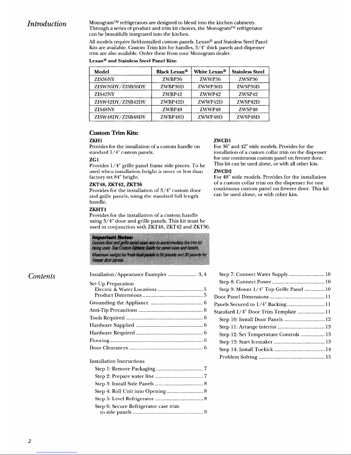
All models require field-installed custom panels. Lexan@ and Stainless Steel Panel
Kits are available. Custom Trim kits for handles, 3/4” thick panels and dispenser
trim are also available. Order these from your Monogram dealer.
Lexan@
and Stainless Steel Panel Kits:
Model
Black Lexan@
White Lexan@ Stainless Steel
ZIS36NY ZWBP36
ZWWP36 ZWSP36
ZISW36DY/ZISB36DY
ZWBP36D
ZWWP36D ZWSP36D
ZIS42NY
ZWBP42 ZWWP42 ZWSP42
ZISW42DY/ZISB42DY
ZWBP42D ZWWP42D ZWSP42D
ZIS48NY
ZWBP48 ZWWP48 ZWSP48
ZISW48DY/ZISB48DY ZWBP48D
ZWWP48D ZWSP48D
Contents
Custom Trim Kits:
ZKH1
Provides for the installation of a custom handle on
standard 1/4” custom panels.
ZG1
Provides 1/4” grille panel frame side pieces. To be
used when installation height is more or less than
factory set 84” height.
ZKT48, ZKT42, ZKT36
Provides for the installation of 3/4” custom door
and grille panels, using the standard full length
handle.
ZKHT1
Provides for the installation of a custom handle
using 3/4” door and grille panels. This kit must be
used in conjunction with ZKT48, ZKT42 and ZKT36.
Installation/Appearance Examples ..................... 3,4
Set Up Preparation
Electric & Water Locations ..................................5
Product Dimensions .............................................5
Grounding the Appliance .......................................6
Anti-Tip Precautions ................................................6
Tools Required .........................................................6
Hardware Supplied ..................................................6
Hardware Required ..................................................6
Flooring ..................................................................... 6
Door Clearances .......................................................6
Installation Instructions
Step 1: Remove Packaging ...................................7
Step 2: Prepare water line ....................................’7
Step 3: Install Side Panels ....................................8
Step 4: Roll Unit into Opening ...........................8
Step 5: Level Refrigerator
....................................
8
Step 6: Secure Refrigerator case trim
to side panels ....................................................9
ZWCD1
For 36” and 42” wide models. Provides for the
installation of a custom collar trim on the dispenser
for one continuous custom panel on freezer door.
This kit can be used alone, or with all other kits.
ZWCD2
For 48” wide models. Provides for the installation
of a custom collar trim on the dispenser for one
continuous custom panel on freezer door. This kit
can be used alone, or with other kits.
Step 7: Connect Water Supply ........................... 10
Step 8: Connect Power ....................................... 10
Step 9: Mount 1/4” Top Grille Panel ...............10
Door Panel Dimensions ......................................... 11
Panels Secured to 1/4” Backing ............................ 11
Standard 1/4” Door Trim Template ....................11
Step 10: Install Door Panels .............................. 12
Step 11: Arrange interior ...................................13
Step 12: Set Temperature Controls ..................13
Step 13: Start Icemaker ......................................l3
Step 14: Install Toekick ......................................l4
Problem Solving ................................................. 15
2
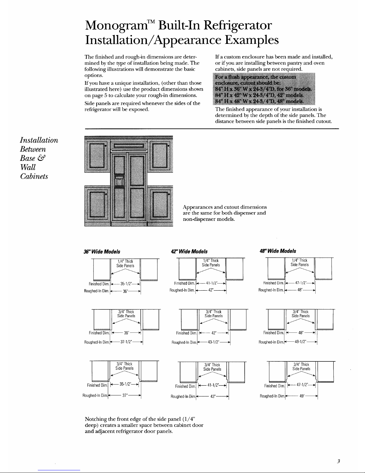
Monogram’” Built-In Refrigerator
Installation/Appearance Examples
The finished and rough-in dimensions are deter-
If a custom enclosure has been made and installed,
mined by the type of installation being made. The
or if you are installing between pantry and oven
following illustrations will demonstrate the basic cabinets, side panels are not required.
refrigerator will be’ exposed. The finished appearance of your installation is
determined by the depth of the side panels. The
distance between side-panels is the finished cutout.
Installation
Between
Base @
Wall
Cabinets
36”Wide Models
Roughed-In Dim. l+----- 36”+
Appearances and cutout dimensions
are the same for both dispenser and
nondispenser models.
42”Wide Models
H ‘g
Finished DirnlL35-1/2’~1
41-1/2”
42”
Roughed-In Dim~— 37”+
Roughed-In ilim.~— 43”+
48” Wide Models
m
Finished Dim lk47-1/2’ql
Roughed-In Dim.~ 48”+
E
Finished Dim,
Roughed-In Dim.
K
+ 48”+
~49-1/2°
4
Roughed-In Diml+—————49”+
Notching the front edge of the side panel (1/4’
deep) creates a smaller space between cabinet door
and adjacent refrigerator door panels.
3
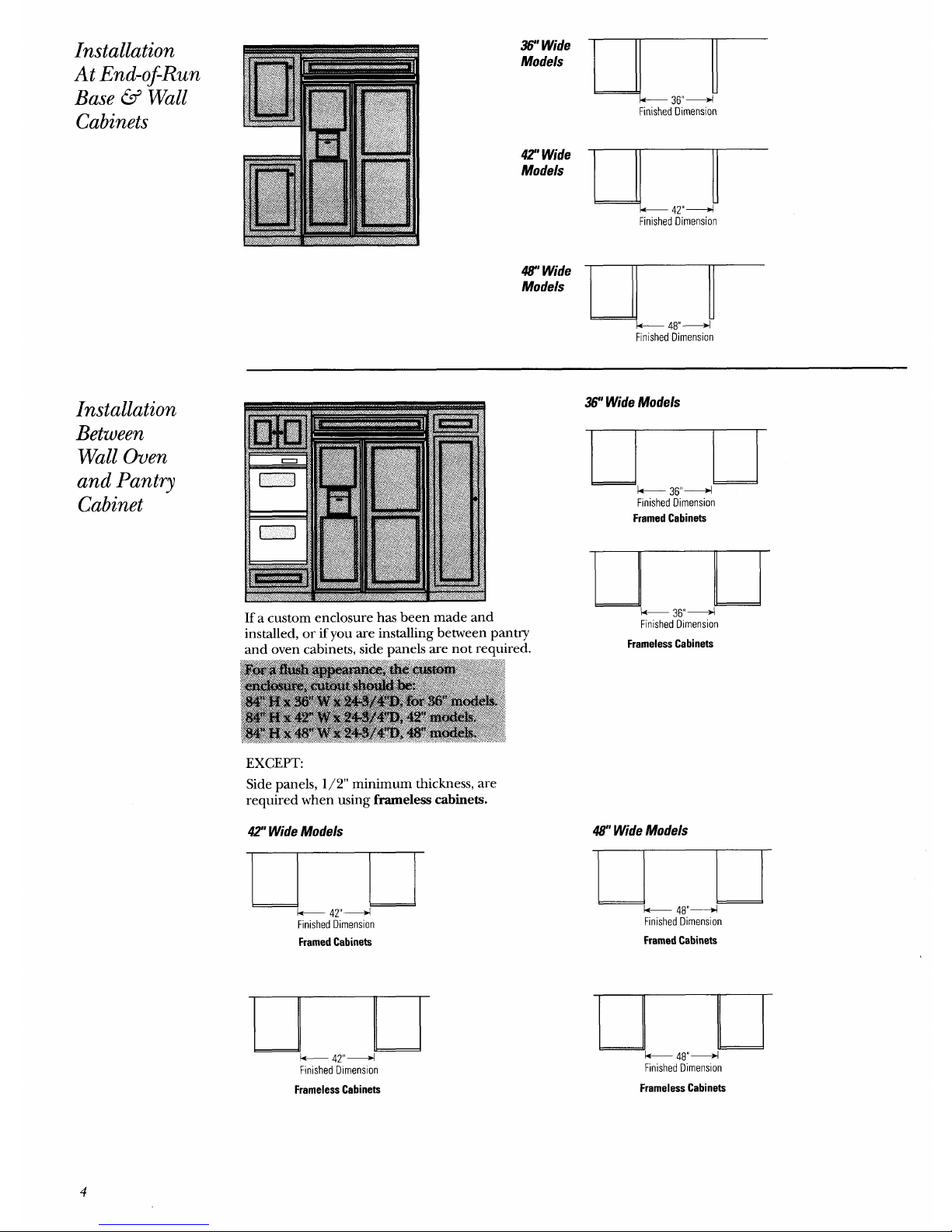
Installation
At End-ofRun
Base @ Wall
Cabinets
Installation
Between
Wall Oven
and Pantry
Cabinet
36” Wide
Models
k--
36”4
Finished Dimension
42?Wide
Models
k
47”+
Finished ~imension
47’ Wide
Models
k 48”+
Finished Dimension
If a custom enclosure has been made and
installed, or if you are installing between pantry
and oven cabinets, side panels are not required.
EXCEPT:
Side panels, 1/2” minimum thickness, are
required when using frarneless cabinets.
42” Wide Models
I
+ 47”+
Finished ~imenslon
FramedCabinets
F!nished Dimension
36” Wide Models
$
& 36”+
Finished Dimension
FramedCabinets
Finished Dimension
43” Wide Models
)
k 48”+
Finished Dimension
FramedCabinets
-.
J-
* 48”+
Finished Dimension
FramelessCabinets
FramelessCabinets
4
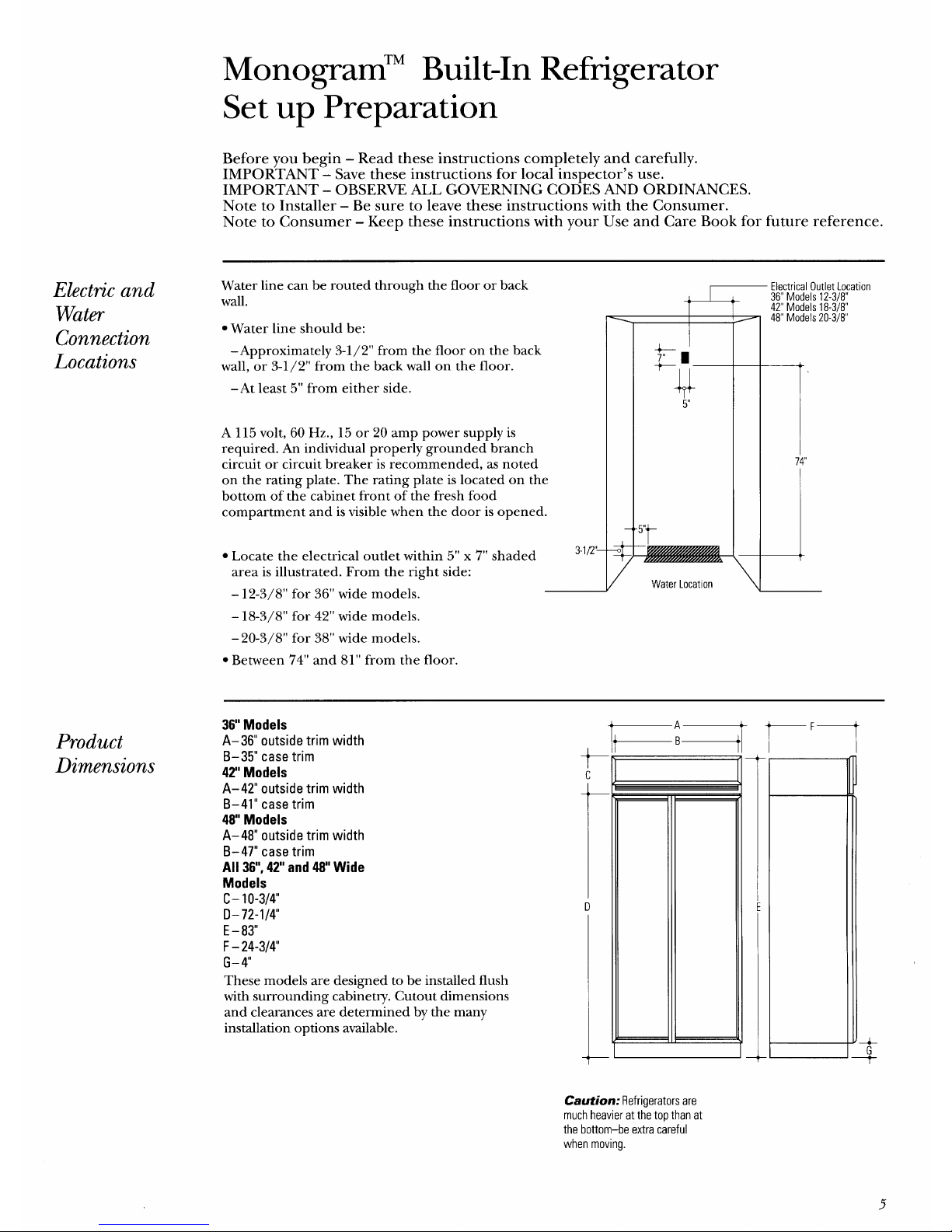
Monogram’” Built-In Refrigerator
Set up Preparation
Before you begin – Read these instructions completely and carefully.
IMPORTANT – Save these instructions for local inspector’s use.
IMPORTANT – OBSERVE ALL GOVERNING CODES AND ORDINANCES.
Note to Installer – Be sure to leave these instructions with the Consumer.
Note to Consumer –
Keep these instructions with your Use and Care Book for future reference.
Electric and
Water
Connection
Locations
Water line can be routed through the floor or back
wall.
● Water line should be:
–Approximately 3-1/2” from the floor on the back
wall, or 3-1/2” from the back wall on the floor.
–At least 5“ from either side.
A 115 volt, 60 Hz., 15 or 20 amp power supply is
required. An individual properly grounded branch
circuit or circuit breaker is recommended, as noted
on the rating plate. The rating plate is located on the
bottom of the cabinet front of the fresh food
compartment and is visible when the door is opened.
● Locate the electrical outlet within 5“ x 7“ shaded
3-l/2’–
area is illustrated. From the right side:
– 12-3/8” for 36” wide models.
– 18-3/8” for 42” wide models.
– 20-3/8” for 38” wide models.
● Between 7’4” and 81” from the floor.
Product
Dimensions
Electrical Outlet Location
36” Models 12-3/8”
42” Models 18-3/8”
48” Models 20-3/8”
/
Water Locat Ion
7
\
—
36” Models
A-36” outside trim width
B–35” case trim
42” Models
t
c
A-42” outside trim width
B–41” case trim
48 Models
A–48” outside trim width
B–47” case trim
All 36”,42” and 48 Wide
Models
c- 10-3/4”
t
.
D-72-l/4
u
E -83”
F- 24-3/4
G- 4“
These models are designed to be installed flush
with surrounding cabinetry. Cutout dimensions
and clearances a;e determined by the many
installation options available.
A
B
I
1
—
—
r
F—
Caution: Refrigerators are
much heavier at the top than at
the bottom–be extra careful
when moving.
5
 Loading...