

Monogram ZIRS36N LH, ZIF36N LH, ZIR36N RH, ZIRS36N RH, ZIF36N RH Technical Service Manual
...
C
GE Consumer Home Services T raining
TECHNICAL SER VICE GUIDE
GE Monogram 36-inch Refrigerator
GE Monogram 36-inch Freezer
MODEL SERIES:
ZIR36N LH - All Fresh Food
ZIR36N RH - All Fresh Food
ZIRS36N LH - All Fresh Food
ZIRS36N RH - All Fresh Food
ZIF36N LH - All Freezer
ZIF36N RH - All Freezer
ZIFS36N LH - All Freezer
ZIFS36N RH - All Freezer
PUB # 31-9047 12/00

!
IMPORTANT SAFETY NOTICE
The information in this service guide is intended for use by
individuals possessing adequate backgrounds of electrical,
electronic, and mechanical experience. Any attempt to repair a
major appliance may result in personal injury and property
damage. The manufacturer or seller cannot be responsible for the
interpretation of this information, nor can it assume any liability in
connection with its use.
WARNING
To avoid personal injury, disconnect power before servicing this
product. If electrical power is required for diagnosis or test
purposes, disconnect the power immediately after performing the
necessary checks.
RECONNECT ALL GROUNDING DEVICES
If grounding wires, screws, straps, clips, nuts, or washers used
to complete a path to ground are removed for service, they must
be returned to their original position and properly fastened.
GE Consumer Home Services Training
Technical Service Guide
Copyright © 2000
All rights reserved. This service guide may not be reproduced in whole or in part
in any form without written permission from the General Electric Company.

Table of Contents
Introduction ............................................................................................................2
Installation Highlights............................................................................................3
Specifications.........................................................................................................5
Nomenclature .........................................................................................................7
Warranty Information..............................................................................................8
Operating Characteristics .....................................................................................10
Mechanical Disassembly .......................................................................................13
Troubleshooting.....................................................................................................29
Component and Connector Locator Views .........................................................32
Schematics .............................................................................................................35
Illustrated Parts Catalog .......................................................................................40
– 1 –

Introduction
The Monogram refrigerator/freezer makes an
eloquent statement of style, convenience, and
kitchen planning flexibility . Whether chosen for it s
purity of design, practical storage arrangements,
or assiduous attention to detail - or for all of these
reasons - the Monogram refrigerator/freezer’s
superior blend of form and function will delight the
customer for years to come.
The Monogram refrigerator/freezer was designed
to provide the flexibility to harmonize with any
kitchen cabinetry. Decorative door insert panels
allow it to match kitchen cabinets or blend with
any kitchen decor. Custom handles are also
available to further personalize the refrigerator/
freezer. Through a series of product and trim kit
choices, the Monogram refrigerator/freezer can be
beautifully integrated into the kitchen.
Since this is designed to be a built-in product,
custom panels are required on the front of the
Monogram refrigerator/freezer . Customers can
consult their kitchen designer or cabinetmaker for
a customized look.
– 2 –
Installation Highlights
Installation Height Panel Height
83-1/2" 7-1/2"
84-1/2" 8-1/2"
9
8
For detailed installation instructions, refer to GE Publication # 49-60055, GE Monogram 36”
Refrigerators and 36” Freezers Custom Options Guide and Installation Instructions.
0"
3/4"
GEA0066
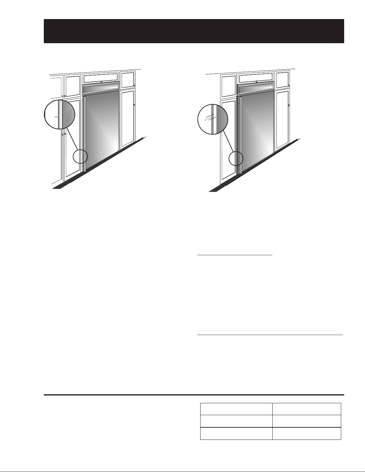
True Flush Installation
In a flush installation, the refrigerator doors
will align evenly with the front face of
adjacent cabinet doors. The refrigerator
blends into the surrounding cabinetry.
Monogram built-in refrigerators and freezers can
be installed flush with typical 24-3/4-in. deep
cabinetry.
When installed semi-flush, the case trim will
conceal slight gaps around the enclosure. The
refrigerator or freezer will project forward
approximately 3/4-in. beyond the front face of
surrounding cabinetry.
In any installation situation, a wide range of
appearance options can be accomplished through
the use of one or more trim kits. See trim kit
descriptions and appearance options in GE
Publication # 49-60055, Installation Instructions,
page 6.
GEA0066
Semi-Flush Installation
These refrigerators can also be installed
semi-flush into an enclosure using the
minimum cutout width. The case trim
creates a frame around the opening.
Side Panel Requirements:
• Side panels are not required whenever the
refrigerator is installed into an enclosure or
between pantry and oven cabinets.
• Side panels are required whenever the sides of
the refrigerator are exposed.
• Side panel sizes vary depending on the type of
installation being made.
To Accomplish an Attractive Installation, You Must:
1. Determine the need for side panels.
2. Determine side panel thickness.
3. Order matching side panels from the cabinet
manufacturer. Be sure to provide the exact
dimensions.
Caution: Maximum panel weight is 50 pounds.
When using custom panels, cut the grille panel
according to the following chart.
– 3 –
Leveling (Refrigerator and Freezer)
IMPORTANT: PLEASE READ CAREFULLY
FOR PERSONAL SAFETY, THISAPPLIANCE MUST BE PROPERLY GROUNDED.
The power cord of this appliance is equipped with a three-prong (grounding) plug that mates with a standard three-prong (grounding) wall receptacle to minimize the
risk of electric shock hazard from this appliance. The customer should have the wall receptacle and circuit checked by a qualified electrician to make sure the receptacle
is properly grounded.
Where a standard two-prong wall receptacle is encountered, it is the personal responsibility and obligation of the customer to have it replaced with a properly grounded
three-prong wall receptacle.
DO NOT, UNDER ANY CIRCUMSTANCES, CUTOR REMOVE THE THIRD (GROUND) PRONG FROM THE POWER CORD.
USAGE
SITUATIONS WHERE THE APPLIANCE’S POWER CORD WILL BE DISCONNECTED INFREQUENTLY
Because of potential safety hazards under certain conditions, we strongly recommend against the use of an adapter plug. However, if you still elect to use an adapter,
where local codes permit, a TEMPORARY CONNECTION may be made to a properly grounded two-prong wall receptacle by the use of a UL listed adapter which is
available at most hardware stores. The larger slot of the adapter must be aligned to provide proper polarity in the connection of the power cord.
CAUTION: Attaching the adapter ground terminal to the wall receptacle cover screw does not ground the appliance unless the cover screw is metal, and not insulated,
and the wall receptacle is grounded through the house wiring. The customer should have the circuit checked by a qualified electrician to make sure the receptacle is
properly grounded. When disconnecting the power cord from the adapter, always hold the adapter with one hand. If this is not done, the adapter ground terminal is very
likely to break with repeated use. Should this happen, DO NOT USE the appliance until a proper ground has again been established.
USAGE
SITUATIONS WHERE THE APPLIANCE’S POWER CORD WILL BE DISCONNECTED FREQUENTLY
Do not use an adapter plug in these situations because frequent disconnecting of the power cord places undue strain on the adapter and leads to eventual failure of the
adapter ground terminal. The customer should have the two-prong wall receptacle replaced with a three-prong (grounding) receptacle by a qualified electrician before
using the appliance.
MAKE SURE PROPER
GROUND EXISTS
BEFORE USE
PREFERRED
METHOD
ENSURE PROPER
GROUND AND
FIRM CONNECTION
BEFORE USE
TEMPORARY METHOD
(Adapter plugs not
permitted in Canada)
197D3266P001 31-5087 9-00 JR
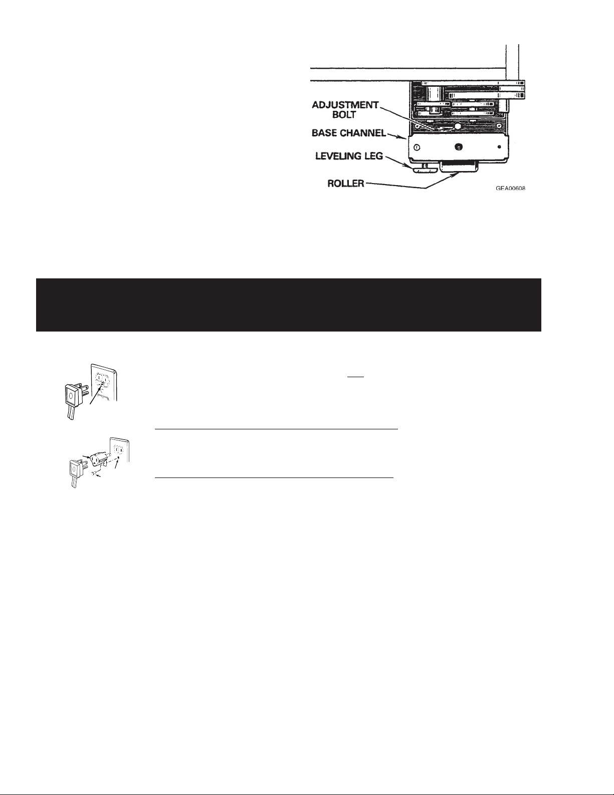
The unit must be level (zero tilt) from front to back
and from side to side. Rollers at the base of the
cabinet, near all four corners, aid the installer in
positioning the unit in its final location. The rear
rollers are adjustable, but the front rollers are nonadjustable.
1. To raise the rear of the cabinet, turn the 7/16in. hex head bolt, located in the base channel
near each front corner of the cabinet.
Note: Four full turns clockwise will raise the rear
roller approximately 3/16-in.
2. To level the front of the cabinet, adjust the
leveling legs at each front corner of the base
channel.
The plug in the wall receptacle is not accessible through the freezer machine compartment
because of the V -shaped condenser. To remove power from the freezer, disconnect the power
cord connector from the machine compartment electrical housing.
– 4 –
Specifications
– 5 –
– 6 –
Nomenclature
r
Z I F S 3 6 N R H
GE Monogram
I = Built-in
Configuration
F = Freezer
R = Refrigerator
(Fresh Food)
Energy
S = Stainless Steel Model
Door Swing
RH = Right Hand
LH = Left Hand
Icemaker
N = GE Non-Icemake
Width (Inches)
– 7 –

Warranty Information
YOUR MONOGRAM WARRANTY
Staple sales slip or cancelled check here. Proof of original purchase
date is needed to obtain service under warranty.
WHAT IS
COVERED
From the Date
of the Original
Purchase
FULL TWO-YEAR WARRANTY
For two years from date of original purchase, we will provide, free of charge, parts and service labor in
your home to repair or replace any part of the refrigerator/freezer that fails because of a manufacturing
defect.
FULL FIVE-YEAR WARRANTY
For five years from date of original purchase, we will provide, free of charge, parts and service labor
in your home to repair or replace any part of the sealed refrigerating system (the compressor, condenser,
evaporator and all connecting tubing) that fails because of a manufacturing defect.
LIMITED ADDITIONAL SEVEN-YEAR WARRANTY ON THE SEALED SYSTEM
For the sixth through twelfth year from the date of the original purchase, we will provide, free of
charge, replacement parts for any part of the sealed refrigerating system (the compressor, condenser,
evaporator and all connecting tubing) that fails because of a manufacturing defect. You pay for
the service trip to your home and for service labor charges.
LIMITED LIFETIME WARRANTY ON ACCURIDE® SLIDES
From the date of the original purchase we will provide, free of charge, replacement parts for
any part of the Accuride Slides that fails because of a manufacturing defect. You pay for the service
trip to your home and for service labor charges.
This warranty is extended to the original purchaser and any succeeding owner for products
purchased for ordinary home use in the 48 mainland states, Hawaii and Washington, D.C.
In Alaska the warranty is the same except that it is LIMITED because you must pay to ship
the product to the service shop or for the service technician’s travel costs to your home.
All warranty service will be provided by our Factory Service Centers or by our authorized Customer
Care® servicers during normal working hours.
Should your appliance need service, during warranty period or beyond, in the U.S.A. call
800.444.1845.
Some states do not allow the exclusion or limitation of incidental or consequential damages, so the
above limitation or exclusion may not apply to you. This warranty gives you specific legal rights, and
you may also have other rights which vary from state to state. To know what your legal rights are in
your state, consult your local or state consumer affairs office or your state’s Attorney General.
Warrantor: General Electric Company. If further help is needed concerning this warranty, write:
Manager—Customer Relations, GE Appliances, Louisville, KY 40225
WHAT IS NOT
COVERED
• Service trips to your home to teach you how to
use the product.
Read your Use and Care material.
If you then have any questions about operating
the product, please contact your dealer or our
Customer Relations office at the address below,
or call, toll free:
GE Answer Center®
800.626.2000
consumer information service
• Replacement of house fuses or resetting of
circuit breakers.
• Damage to the product caused by accident, fire,
floods or acts of God.
• Failure of the product if it is used for
other than its intended purpose or used
commercially.
• Improper installation.
If you have an installation problem, contact
your dealer or installer. You are responsible for
providing adequate electrical, plumbing and
other connecting facilities.
• Loss of food due to spoilage.
WARRANTOR IS NOT RESPONSIBLE FOR
CONSEQUENTIAL DAMAGES.
– 8 –
Notes
– 9 –

Operating Characteristics
Note: Refer to Component and Connector
Locator Views.
• Refer to Schematics and Strip Circuits.
Component Description
The compressor, dryer, and condenser are
located in the machine compartment on the top of
the cabinet. The evaporator is located on the
inside of the cabinet at the bottom of the back wall.
The capillary is soldered to the compressor
suction line. This arrangement serves as a heat
exchanger . The temperature control is located in
the top of the inside of the cabinet. The evaporator
fan is also located in the top of the inside of the
cabinet, behind the temperature control.
Electrical Operation (Freezer)
115V is provided from the power source to the
temperature control. The temperature control is a
thermostatic switch that closes when cabinet
temperature is higher than the control setting.
When closed, the temperature control provides
115V to the defrost control. The defrost control
contains a motor/cam mechanism that switches
the defrost control between defrost mode and
cooling mode. When in cooling mode, the defrost
control provides 115V to the compressor and to
the condenser fan. The condenser fan and
compressor always operate at the same time. In
addition to the compressor and condenser fan, the
defrost control provides 115V (in cooling mode)
through the cabinet door switch (evaporator fan
circuit) to the evaporator fan delay switch. The
door switch opens the evaporator fan switch
circuit when the cabinet door is open. The
evaporator fan delay switch opens when the
evaporator temperature has raised to 45°F and
closes when the evaporator temperature has
lowered to 25°F. When closed, the cabinet door
switch and evaporator fan delay switch provide
115V to the evaporator fan.
Electrical Operation (Refrigerator)
115V is provided from the power source to the
temperature control. The temperature control is a
thermostatic switch that closes when cabinet
temperature is higher than the control setting.
When closed, the temperature control provides
115V to the drain pan fan and defrost thermostat
switch. When closed, the defrost thermostat
switch provides 115V to the compressor and to
the condenser fan. The condenser fan and
compressor always operate at the same time.
115V is also provided from the power source to
the evaporator fan. The door switch opens the
evaporator fan switch circuit when the cabinet
door is open.
Air Movement
The cabinet is designed so that when the
evaporator fan is operating, air is drawn through
the evaporator and then up the back of the cabinet
through two ducts. At the top of the cabinet, the air
is drawn out of the ducts and through the
evaporator fan into the upper rear duct. Air moves
out of the upper rear duct and into the main part of
the cabinet. In the main part of the cabinet, the
cold air falls into the lower part of the cabinet and
is drawn into the evaporator again.
– 10 –
Refrigerator Air Flow
GEA00637
Freezer Air Flow
GEA00860
– 11 –
Notes
– 12 –

Mechanical Disassembly
Table of Contents
Door Handle (Refrigerator and Freezer) .............................................................. 15
Door Gasket (Refrigerator and Freezer)
Door Hinges (Refrigerator
Upper Door Hinge ............................................................................................. 15
Door Closure Mechanism.................................................................................15
Lower Door Hinge ............................................................................................. 16
Door Adjustment............................................................................................... 16
Door Assembly (Refrigerator
Icemaker (Freezer) .................................................................................................17
Icemaker Water V alve and W ater Line (Freezer)...................................................17
T o Replace the W ater V alve............................................................................... 17
T o Replace the Water Line from the
Water V alve to the Fill Tube Grommet......................................................... 18
and
Freezer) .............................................................. 15
and
................................................................15
Freezer) ......................................................... 16
Upper Light Shield (Refrigerator
Control Panel (Refrigerator
Upper Light Assembly (Refrigerator and Freezer)
Rear Duct (Refrigerator and Freezer)
T emperature Control (Refrigerator
Evaporator Fan (Refrigerator
and
Freezer) ...................................................19
and
Freezer) ............................................................ 19
................................................20
.....................................................................20
and
Freezer)
and
Freezer) ......................................................... 21
...................................................20
– 13 –

Storage Bin (Refrigerator
To Remove Only the Storage Bin......................................................................22
To Remove Both the Storage Bin and
the Bin Support ............................................................................................. 22
To Remove the Showcase Lid ........................................................................... 22
and
Freezer) ................................................................ 22
Storage Bin Slide Support and Center Divider (Refrigerator and Freezer) ...........
To Remove the Left or Right Slide Support .....................................................22
To Remove the Center Divider .......................................................................... 23
Evaporator Cover (Refrigerator
Defrost Heater (Freezer Only)................................................................................23
Evaporator (Refrigerator
Drain Pan Fan (Refrigerator
Grille Panel (Refrigerator
Rocker Switches (Refrigerator
and
and
Freezer)
and
Freezer) .................................................................24
Only
)......................................................................... 24
Freezer)
and
...................................................................25
Freezer) ........................................................ 25
.........................................................23
22
Defrost Control (Freezer) ....................................................................................... 26
PTCR Relay/Overload Cover (Refrigerator and Freezer)
PTCR Relay (Refrigerator
Overload (Refrigerator
Run Capacitor (Refrigerator
Slide-Out Chassis (Refrigerator
and
Freezer)................................................................ 26
and
Freezer).....................................................................27
and
Freezer)............................................................ 27
and
Freezer) ...................................................... 27
........................................26
– 14 –
8
The plug in the wall receptacle is not accessible through the freezer machine compartment
because of the V-shaped condenser. To remove power from the freezer, disconnect the power
cord connector from the machine compartment electrical housing.
Door Handle (Refrigerator and Freezer)
1. Open door to 90 degrees.
2. Remove 6 Phillips screws from the full-length
aluminum handle.
GEA0061
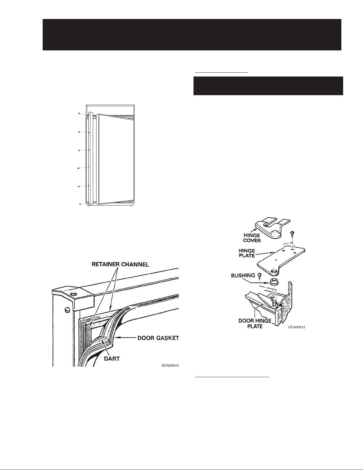
Door Gasket (Refrigerator and Freezer)
Door Hinges (Refrigerator and Freezer)
Upper Door Hinge
Note: There is no adjustment for the upper hinge
assembly.
1. Remove the grille panel (see page 25).
2. Remove 3 Phillips screws and the vent guard.
3. Carefully pry the wire guard above the hinge
upward by inserting a flat head screwdriver
between the bottom edge of the wire guard and
the hinge.
Note: The plastic hinge cover is held by doublesided adhesive tape.
4. Remove the hinge cover.
5. Remove T-20 Torx screws (3) securing the
upper hinge to the top of the cabinet.
Note: The door gasket is held in a retainer
channel.
1. Pull the old gasket out of the channel.
2. Soak the new gasket in warm water to make it
more pliable.
3. Using the back of a teaspoon, push the barbed
edge of the gasket into the retaining channel.
Note: The inner door panel is foamed in place and
is available only as a complete assembly with the
exterior door panel.
6. Remove the hinge and bushing.
7. Remove T -20 Torx screws (4) and the hinge
from the door .
Door Closure Mechanism
The door closure mechanism uses a spring to
provide positive door closure from 30 degrees. The
door closure mechanism actuator arm has a
spring attached to the rear and is supported by
guide rollers on either side of the base channel.
The roller circumferences and the actuator arm
detents are matched for smooth operation. The
arm is attached to the door with an Allen head
shoulder bolt.
– 15 –
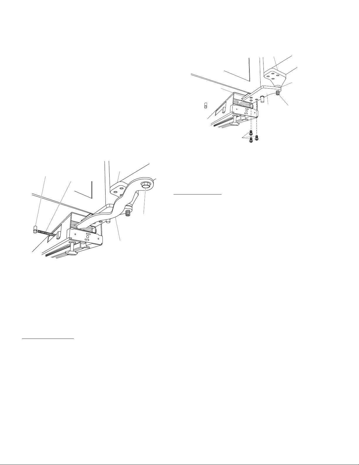
The closure mechanism allows easy opening to
4
3
g
B
approximately 90 degrees, where the arm has a
detent to permit the door to remain open at 90
degrees with minimal tension. Once the door is
opened beyond 90 degrees, the closure
mechanism pulls the door open until the closure
arm engages the door stop at approximately 140
degrees. The reverse action occurs when the door
is closed.
Note: Note the placement of spacers and washers
on the actuator arm for reassembly.
• The actuator arm is spring loaded with moderate
spring tension.
2. Remove T-20 Torx screws (3), base channel
spacer , and hinge from the underside of the
cabinet.
Hinge
ase Channel Spacer
Hinge
Bushin
Hinge
Pin
1. Remove the 5/16-in. bolt, washers, and spacer
from the door and actuator arm.
Door
Hinge
Pin
Spring
5/16"
Bolt
Actuator
Arm
GEA0066
2. Remove the icemaker water line from the door
closure mechanism (see page 17).
3. Remove 5 screws. The mechanism is now
loose from the cabinet.
4. Disconnect the spring from the pin on the
bottom of the cabinet.
Lower Door Hinge
1. Remove the door (see the following
procedure).
Note: Note the placement of spacers and washers
for reassembly.
Hinge
Screws
GEA0066
3. Remove T-20 Torx screws (4) fastening the
hinge to the bottom of the door .
4. Remove the hinge.
Door Adjustment
Be sure the top hinge does not hit the cabinet trim.
Adjust the door up or down by turning the threaded
hinge pin on the bottom hinge.
Door Assembly (Refrigerator and Freezer)
WARNING: The door assembly must be removed
by two people.
WARNING: Use the appropriate safety equipment
and lifting techniques.
Caution: Use wood or a heavy plastic sheet to
protect the floor where the door will be placed.
1. Remove all food and bins from the inner door
liner.
Note: Note the placement of spacers and
washers on the actuator arm for reassembly.
• The actuator arm is spring loaded with moderate
spring tension.
2. Remove the 5/16-in. bolt, washers, and spacer
from the door and actuator arm (see the
previous procedure for detailed art).
3. Remove the grille panel (see page 25).
4. Remove 3 Phillips screws from the vent guard.
5. Carefully pry the wire guard above the upper
hinge upward by inserting a flat head
screwdriver between the bottom edge of the
trim and the hinge.
– 16 –
Note: The plastic hinge cover is held by double-
6
6
sided adhesive tape.
4. Unplug the icemaker from the freezer wall and
remove.
6. Remove the hinge cover (see page 15 for
detailed art).
7. Remove T-20 Torx screws (3) securing the
upper hinge to the top of the cabinet.
8. Remove the upper hinge and bushing.
Note: Do not lose lower hinge bushing during
door removal.
9. Pull the top of the door outward until it clears
the top cabinet frame and carefully lift the door
off the lower hinge. Place door on the
protected floor area.
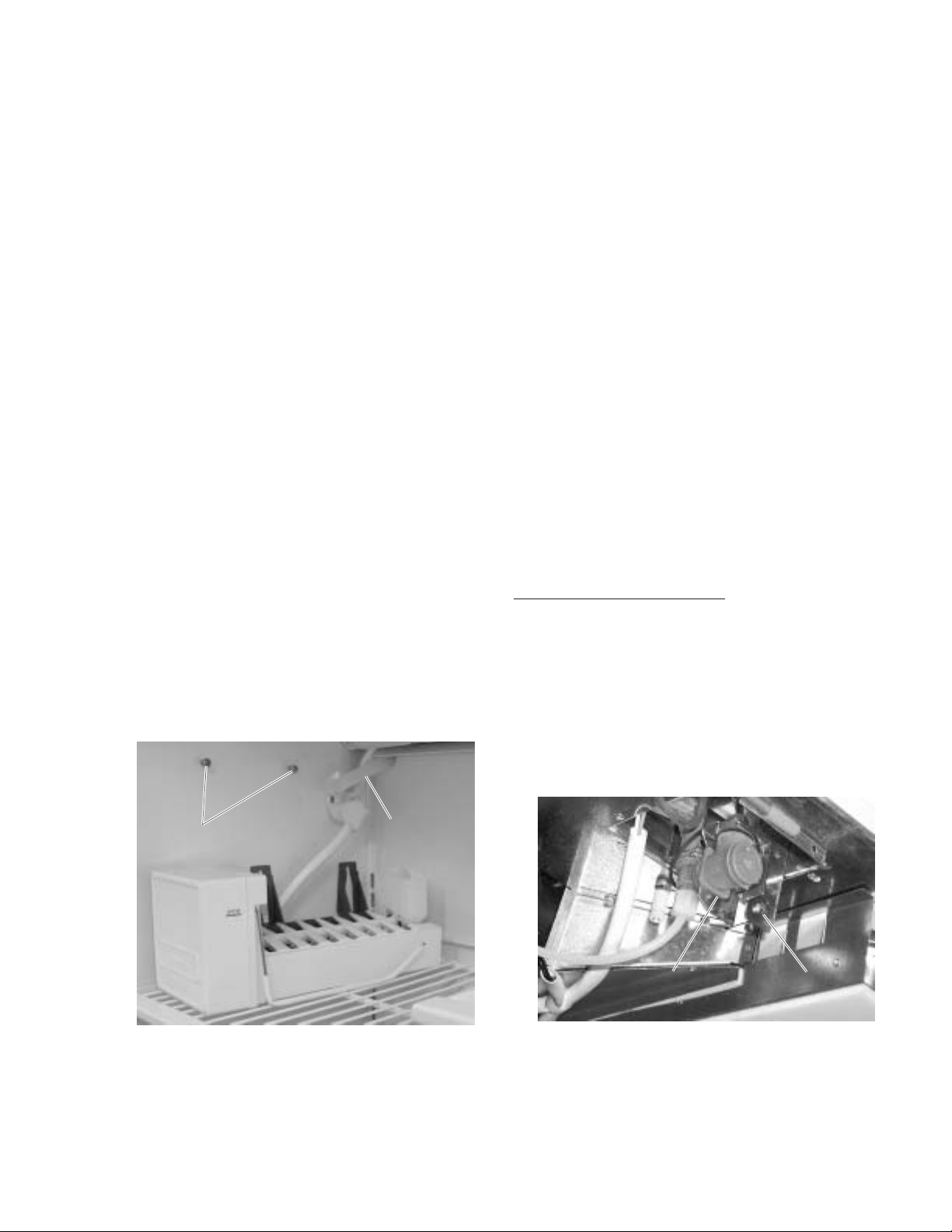
Icemaker (Freezer)
The icemaker is mounted to the upper left wall of
the freezer cabinet. Under normal operating
conditions, temperatures, door openings, and food
load, the icemaker is capable of producing
approximately 100 cubes in a 24 hour period.
1. Loosen 2 Phillips screws above the icemaker.
To service the icemaker, refer to GE Publication
31-4591, 1985 Icemakers.
Icemaker Water V alve and W ater Line
(Freezer)
The water valve is mounted under the cabinet,
beside the door closure mechanism. The valve has
a 1/4-in. stub of copper tubing to provide a
connection to the house water supply. Refer to GE
Publication # 49-60055, GE Monogram 36”
Refrigerators and 36” Freezers Custom
Options Guide and Installation Instructions for
connecting the freezer to the water supply.
A low-pressure plastic water line supplies water to
the icemaker from the water valve. The plastic
water line is routed from the water valve, under the
cabinet, through the back of the door closure
mechanism, and up the outside (back) of the
cabinet. At the top of the outside (back) of the
cabinet, the water line is connected to the fill tube
grommet. The icemaker fill tube is also plastic.
Caution: Use care to avoid damaging the water
tubing.
2. Slide the icemaker upward and pull off from the
screws.
3. Set the icemaker on the top freezer shelf.
ScrewsScrews
Water LineWater Line
GEA0062
To Replace the Water Valve:
Note: Some water may leak from the water supply
line and valve when they are disconnected.
1. Shut off the water supply to the freezer.
2. Remove the metal protective cover.
3. Remove 1 screw and lower the water valve
from the freezer .
ScrewScrewWater ValveWater Valve
GEA0066
– 17 –

4. Disconnect the wiring harness connector and
7
8
water line from the water valve.
Copper
ConnectorConnector
Water
Water
Line
Line
Copper
Tubing
Tubing
Water
Water
Valve
Valve
GEA0066
5. Disconnect the copper tubing from the water
valve.
3. Loosen 3 clamp screws.
Fill Tube GrommetFill Tube Grommet
To Replace the Water Line from the Water V alve to
the Fill Tube Grommet:
Note: Some water may leak from the water supply
line and valve when they are disconnected.
1. Shut off the water supply to the freezer.
2. Remove the unit from its installation (see GE
Publication 49-60055, GE Monogram 36”
Refrigerators and 36” Freezers Custom
Options Guide and Installation
Instructions, pages 12-17).
Clamp ScrewsClamp Screws
Water LineWater Line
GEA0063
4. Loosen the clamp at the fill tube grommet.
Caution: Do not lose the tubing sleeve when
removing the water line from the fill tube grommet.
The sleeve must be used during reassembly to
avoid leaking.
5. Remove the water line from the fill tube
grommet.
6. Remove the sleeve from the water line.
7. Slide the water line down and out of 3 clamps.
– 18 –

8. Disconnect the water line from the water valve.
1
3
9
st
GEA00643
ScrewsScrewsUpper
Light
Assembly
Upper
Light
Assembly
Water
Water
Valve
Valve
3. Pull the panel forward.
Note: On the rear of the control panel is a small
molded post which aligns the temperature control
knob. When reinstalling the control panel, make
certain to align the control knob with the post.
ClampClamp
Water
Water
Line
Line
Door Closure
Door Closure
Mechanism
Mechanism
GEA0068
9. Slide the water line out of the door closure
mechanism and clamp (on the underside of the
cabinet).
Upper Light Shield (Refrigerator and
Freezer)
1. Grasp the shield on each side.
2. Gently squeeze the front left and right sides
toward the center, then push toward the back.
Molded Po
GEA0061
Upper Light Assembly (Refrigerator and
Freezer)
1. Remove the upper light shield (see the
previous procedures).
2. Remove 4 Phillips screws and the upper light
assembly.
3. Lower the shield while disengaging it from the
control panel and then from the rear duct.
Control Panel (Refrigerator and Freezer)
1. Remove the upper light shield (see the
previous procedure).
2. Loosen (do not remove) 4 Phillips screws
behind the panel.
Control
Control
Knob
Knob
ScrewsScrews
Control
Control
Panel
Panel
GEA0065
3. Disconnect 2 wires from the temperature
control.
– 19 –

Note: The wires may be reconnected on either
5
2
6
7
side of the control.
Screws for Control PanelScrews for Control Panel
Temperature
Temperature
Control
Control
Knob Stem
Knob Stem
2. Remove 4 screws from the rear duct.
Refrigerator
ScrewsScrews
ScrewsScrews
WiresWires
Temperature
Temperature
Control
Control
Control Panel and
Control Panel and
Control Knob shown
Control Knob shown
removed for clarity
removed for clarity
GEA0064
4. Disconnect the connector.
ConnectorConnector
Rear Duct (Refrigerator and Freezer)
GEA0064
Rear DuctRear Duct
GEA0064
Freezer
ScrewsScrewsScrewsScrews
Rear DuctRear Duct
GEA0062
Caution: When removing and installing the rear
duct, insert a piece of plastic or card stock
between the cover and the unit’s side walls to
avoid scratching the walls.
3. Ease the rear duct away from the back wall.
Caution: When reinstalling the rear duct, be sure
that the wires for the upper lights and temperature
control capillary fit in the cover’s notches.
Note: When reinstalling the rear duct, put the white
screws in the holes facing the freezer door.
1. Remove the icemaker (see page 17) and
upper light shield (see page 19).
Temperature Control (Refrigerator and
Freezer)
1. Remove the upper light shield (see page 19).
2. Remove the control panel (see page 19).
3. Remove the upper light assembly (see page
17).
4. Remove the rear duct (see the previous
procedure).
– 20 –

Note: The screw does not need to be loosened
2
4
3
4
rFan Motor
r
from the clamp to complete the following step.
5. Remove the capillary from the clamp at the
evaporator fan.
Note: During reassembly, you must place the end
of the capillary through the clamp and on the foam
pad.
CapillaryCapillary
ClampClamp
Foam
Foam
Pad
Pad
GEA0068
Evaporator Fan (Refrigerator and Freezer)
1. Remove the icemaker (freezer only), upper
light shield, and rear duct (see pages 17-20).
2. Remove 2 screws from the fan motor bracket
and carefully lower the evaporator fan
assembly.
ScrewsScrews
GEA0068
3. Disconnect the wire connector from the fan
motor.
ScrewsScrews
Fan Moto
Fan Moto
Bracket
Bracket
6. Remove 2 Phillips screws and the temperature
control from the bracket.
ScrewsScrews
BracketBracket
WiresWires
Temperature
Temperature
Control
Control
GEA0065
7. Disconnect 2 wires from the temperature
control if not already done.
FanFan
Wire
Wire
Connector
Connector
Fan MotorFan Motor
GEA0068
4. Remove the fan from the motor.
5. Remove 2 screws and the fan motor bracket
from the fan motor .
– 21 –

Storage Bin (Refrigerator and Freezer)
5
1
2
3
4
4
tSupport
t
To Remove Only the Storage Bin:
1. Pull the bin out until it stops.
2. Lift the front edge of the bin upward until it
snaps out of the bin support.
BinBin
3. At the same time, use a finger to push down
on the right release lever .
GEA0062
4. While holding the levers, slide the bin out.
To Remove the Showcase Lid:
1. Remove 1 Phillips screw and plastic washer
from the hinge pin in the center support.
Bin SupportBin Support
GEA0061
3. Pull the bin forward while lifting it up and out
from the wire frame.
To Remove Both the Storage Bin and the Bin
Support:
Note: For large hands, it is much easier to remove
the storage bin first, then release the levers to
remove the bin support.
1. Pull the bin out until it stops.
Release LeverRelease Lever
GEA0062
Hinge Pin
Hinge Pin
Screw
Screw
GEA0062
2. Grasp the showcase lid with both hands and
pull off the hinge pins.
Storage Bin Slide Support and Center
Divider (Refrigerator and Freezer)
To Remove the Left or Right Slide Support:
1. Remove the appropriate storage bins (see the
previous procedure).
2. Remove 6 Phillips screws and the slide
support from inside of cabinet.
2. Grasp the bin from the sides. Use a finger to
pull up on the left release lever .
GEA0062
– 22 –
ScrewsScrews
SlideSlide
Slide
Slide
Suppor
Suppor
GEA0063

3. Remove 2 Phillips screws and the small ball
2
3
5
rEvaporator
r
1
Defrost Heater
bearing slide from slide support.
4. Remove the evaporator cover from cabinet.
4. Remove 3 Phillips screws and the large ball
bearing slide from slide support.
To Remove the Center Divider:
1. Remove all storage bins and bin supports (see
page 22).
ScrewsScrews
Evaporator CoverEvaporator Cover
Lower Light SocketsLower Light Sockets
ScrewsScrews
GEA0063
Evaporato
Evaporato
Cover
Cover
Center
Center
Divider
Divider
GEA0063
2. Remove 10 Phillips screws (5 on each side)
and center divider from inside of cabinet.
Evaporator Cover (Refrigerator and
Freezer)
The evaporator cover is attached to the lower
backside of the cabinet interior .
1. Remove the showcase lids and bins (see
page 22) and the center divider (see the
previous procedure).
2. Remove 4 Phillips screws from the evaporator
cover.
GEA0063
Defrost Heater (Freezer Only)
Note: The refrigerator does not have a defrost
system. It defrosts naturally during the OFF cycle.
1. Remove the showcase lids (see page 22), fulllength shelf, bins (see page 22), and the center
divider (see page 23).
2. Remove the evaporator cover (see the
previous procedure).
3. Disconnect 2 defrost heater connectors.
Evaporator
Clip
Defrost Heater
ConnectorConnectorConnectorConnector
3. Pull the evaporator cover forward. Disconnect
wiring from lower light sockets.
– 23 –
ClipsClips Defrost Heater
Defrost Heater
GEA0064

Caution: Use care when handling these
7
rDefrost Heater
)(Freezer Only)
r
)
sScrews
s
components to avoid damaging the evaporator and
refrigerant lines. Do not move the evaporator any
more than necessary when accessing the defrost
heater clips.
4. Remove 4 screws to access the bottom of the
evaporator . Do not disconnect the refrigerant
lines.
5. Remove 2 clips and the heater from the
evaporator.
Caution: The foam air guides on the left- and righthand sides of the evaporator must be in place
during reassembly.
Evaporator (Refrigerator and Freezer)
1. Disconnect the electrical power.
2. Recover the refrigerant.
3. Remove the evaporator cover (see the
previous procedure).
8. Remove 4 screws that hold the evaporator to
the cabinet and tilt the evaporator forward.
9. Remove the defrost heater (freezer only - see
the previous procedure).
10. Desolder the capillary tube from the
evaporator .
Caution: To prevent damage to the capillary tube,
the capillary tube must be desoldered first.
Caution: Protect cabinet wiring harness from heat
during desoldering and resoldering.
Note: It may be necessary to remove foam rubber
insulation from suction line to access solder union.
11. Desolder the suction line. Use a pair of pliers
to hold the evaporator .
12. Remove evaporator.
13. Using a file, score the capillary tube just above
the old solder and break the solder-covered
section off. This will help prevent the capillary
tube from becoming plugged when resoldering.
4. Disconnect 2 defrost heater connectors
(freezer only - see the previous procedure).
5. Remove 2 thermostat switches (1 switch only
on refrigerator) from evaporator .
6. Remove foam air guides located on each side
of the evaporator.
7. Disconnect the lower interior harness
connector from the cabinet harness connector.
Remove the lower interior harness from the
cabinet.
Caution: When removing the evaporator, use care
to avoid damaging the finish on the unit walls.
Defrost Thermostat Switch
Defrost Thermostat Switch
(Pink and Orange Wires)
(Pink and Orange Wires)
EvaporatorEvaporator
Screw
Screw
14. Position the new evaporator in the cabinet.
Insert the suction line and capillary tube into
the evaporator .
15. Braze the suction line to the evaporator using
silfos.
16. Braze the capillary tube to the evaporator
using silfos.
17. Install a replacement dryer.
18. Evacuate and recharge the system using
currently accepted procedures.
Drain Pan Fan (Refrigerator Only)
The Monogram 36-in. refrigerator has an auxiliary
evaporation fan located behind the water valve.
The purpose of this fan is to improve the
evaporation rate of drain water .
Should the fan fail or the customer complain of
excessive fan noise, follow the instructions below
for Heater Kit WR49X10016.
Fan Delay Thermostat Switch
Fan Delay Thermostat Switch
(Red and Blue Wires)
(Red and Blue Wires)
Defrost Heate
Defrost Heate
(Freezer Only
(Freezer Only
GEA0064
Note: This heater kit is also used in the Monogram
36-in. Bottom Mount Refrigerator .
• Disconnect the power to the unit before
proceeding.
1. Remove the unit’s toekick.
2. Disconnect the leads from the auxiliary
evaporation fan.
– 24 –

3. Attach 2 jumper wires with 1/8-in. spade
3
t-
4
ly
7
terminals to the fan leads.
4. Use adhesive clips to hold the wires against
the bottom of the unit. Make sure they do not
interfere with the installation or removal of the
drain pan.
Grille Panel (Refrigerator and Freezer)
WARNING: To avoid personal injury when
servicing the components in the machine
compartment, stand on a ladder which will give
enough support to allow removal of the top panel
and safely allow access to service the unit.
1. Place your thumbs under the left and right
corners of the grille panel.
2. Push up on the panel and pull it toward you.
Grille
Panel
Heater assembly is laid into place and attached by folding the front
tabs down. The rear flange of the heater assembly is over the nex
to-last tube of the auxiliary condenser. Note: Edge trim is used
wherever a wire is laying over a sharp edge and wires must be
routed so as to prevent contact with the drain pan.
GEA0061
5. Remove the drain pan. Be careful not to spill
water from the pan.
6. Install the heater assembly over the auxiliary
condenser.
Connect Heater
Adhesive Clips
Fan
Connect Jumper
to Jumper
to Fan Lead
Heater
Assemb
GEA0061
GEA0061
Rocker Switches (Refrigerator and Freezer)
Three switches are located at the top of the inside
compartment. They are, from left to right, the
evaporator fan switch (black) and 2 switches
(green) for the upper and lower light assemblies.
The switches are activated by opening the door.
1. Disconnect the electrical power.
2. Remove the grille panel (see the previous
procedure).
Note: Mark the wires for reinstallation.
3. Remove 2 connectors from the switch.
ConnectorsConnectors
7. Connect the heater leads to the jumper
harness lead.
Note: Make sure the directional arrow on the drain
pan is pointed to the rear of the unit.
8. Reinstall the drain pan and toekick.
Evaporator
Evaporator
Fan Switch
Fan Switch
Upper and Lower
Upper and Lower
Light Switches
Light Switches
4. Open the unit’s door .
5. Push in on the retainer clip on the side of the
switch, and push the switch down to remove.
– 25 –
GEA00648

9
5
0
1
The plug in the wall receptacle is not accessible through the freezer machine compartment
because of the V-shaped condenser. To remove power from the freezer, disconnect the power
cord connector from the machine compartment electrical housing.
Defrost Control (Freezer)
1. Remove the grille panel (see page 25).
2. Remove 2 Phillips screws and the defrost
control from the front baffle.
Defrost ControlDefrost Control
ScrewsScrews
GEA0063
PTCR Relay/Overload Cover (Refrigerator
and Freezer)
1. Remove the grille panel (see page 25) and
vent guard.
2. Insert a flat head screwdriver under the tab on
the cover’s top surface.
TabTab
GEA0066
3. Pry the cover up slightly while pulling it back to
remove.
3. Disconnect the connector from the defrost
control.
ConnectorConnector
Defrost
Defrost
Control
Control
GEA0065
Note: It may be necessary to manually switch
(set) the new defrost control to cooling mode or
defrost mode.
PTCR Relay (Refrigerator and Freezer)
1. Remove the grille panel (see page 25) and
vent guard.
2. Remove the PTCR relay/overload cover (see
the previous procedure).
3. Pull the relay straight out from the compressor .
PTCR
PTCR
Relay
Relay
GEA0066
4. Disconnect 3 connectors from the PTCR
relay.
– 26 –

Overload (Refrigerator and Freezer)
2
0
1. Remove the grille panel (see page 25) and the
vent guard.
2. Remove the PTCR relay/overload cover (see
page 26).
3. Remove the PTCR relay (see the previous
procedure).
4. Pull the overload straight out.
OverloadOverload
3. Discharge the run capacitor with a
screwdriver.
4. Remove 1 Phillips screw and the run capacitor
from the machine compartment.
Slide-Out Chassis (Refrigerator and
Freezer)
The machine compartment contains the
compressor and condenser on a slide-out chassis
that can be pulled out of the compartment to
facilitate servicing the refrigeration system.
1. Remove the grille panel (see page 25).
PTCR
PTCR
Relay
Relay
GEA0066
5. Disconnect 1 connector from the overload.
Run Capacitor (Refrigerator and Freezer)
1. Remove the grille panel (see page 25).
2. Disconnect the connector from the run
capacitor.
ConnectorConnector
2. Remove the vent guard and wire guard.
3. Remove 3 switches (see page 25).
4. Remove the plastic clamp for the power cord.
5. Loosen the 7/16-in. bolts (2) on the chassis
mount.
Caution: A void kinking the refrigeration tubing
while sliding the chassis out and back in.
6. Pull the chassis forward (approximately 6 in.)
until it reaches the stops provided in tracks.
Work the refrigeration tubing as you pull the
chassis out.
GEA00620
ScrewScrew
GEA0067
– 27 –

Notes
– 28 –

Troubleshooting
Note: Refer to Operating Characteristics before
choosing a troubleshooting procedure.
• Refer to Schematics and Strip Circuits.
Door Hard to Reopen Immediately After
Closing
The door has an extremely good seal and may be
hard to reopen for 10 to 15 seconds after closing.
If necessary, install vacuum break WR49X10026.
Low or No Cooling (Warm Food
Temperature)
Check for the following problems:
1. Condenser and/or grille dirty/clogged.
Unplug unit and clean condenser and grille.
2. Interior lights remain on. Check to see that
interior lights turn off when door switches are
pressed.
3. Door gasket does not seal. Check for
damaged or leaking door gasket.
4. Compressor does not operate. Go to
Compressor Does Not Operate
troubleshooting.
5. Condenser fan does not operate. Go to
Condenser Fan Does Not Operate
troubleshooting.
6. Evaporator fan does not operate. Go to
Evaporator Fan Does Not Operate
troubleshooting.
7. Evaporator is frosted (frost on evaporator
cover). Go to Defrost System Check.
8. Refrigeration system faulty. Go to
Refrigeration System Check.
Compressor Does Not Operate
Check for the following problems:
Note: The defrost control must be in cooling mode
to operate the compressor (provide 115V to the
compressor overload). It may be necessary to
manually rotate the defrost control to cooling mode
before checking for voltage at the compressor
overload.
1. 115V not present at compressor overload
(Freezer Only). If 115V is not present at the
compressor overload, check for an open
temperature control or an open defrost control
(cooling mode - terminals 3 and 4 are closed).
Note: The compressor and the condenser fan
should always operate at the same time. If the
condenser fan is operating, the temperature
control and defrost control are OK.
115V not present at compressor overload
(Refrigerator Only). If 115V is not present at
the compressor overload, check for an open
temperature control or an open defrost switch.
Note: The compressor and the condenser fan
should always operate at the same time. If the
condenser fan is operating, the temperature
control and defrost switch are OK.
2. Overload open. High heat or high current
draw will cause the overload to open. The
overload should close when the temperature
lowers to normal or when normal current draw
is present.
3. PTCR relay open. Check for continuity
between terminals 1 and 5. If there is no
continuity , replace the PTCR relay. If there is
continuity, check for continuity between
terminals 1 and 6. If there is no continuity,
replace the PTCR relay.
4. Run capacitor faulty.
5. Open wire or faulty connector. Refer to
Schematics and Strip Circuits.
6. Compressor motor faulty. Check resistance
across the compressor motor. Refer to
Schematics and Strip Circuits for resistance
values.
7. Compressor mechanically stalled.
Condenser Fan Does Not Operate
Check for the following problems:
1. Condenser fan faulty. Check for a stuck fan
motor. Check resistance across the fan motor.
Refer to Schematics and Strip Circuits for
resistance values.
2. 115V not present at condenser fan (Freezer
Only). If 115V is not present at the condenser
fan, check for an open temperature control or
an open defrost control (cooling mode terminals 3 and 4 are closed). Note: The
– 29 –

compressor and the condenser fan should
always operate at the same time. If the
compressor is operating, the temperature
control and defrost control are OK.
115V not present at condenser fan
(Refrigerator Only). If 115V is not present at
the codenser fan, check for an open
temperature control or an open defrost switch.
Note: The compressor and the condenser fan
should always operate at the same time. If the
compressor is operating, the temperature
control and defrost switch are OK.
3. Orange wire open on neutral side of
condenser fan. Refer to Schematics and Strip
Circuits.
Evaporator Fan Does Not Operate
Check for the following problems:
1. Evaporator fan faulty. Check for a stuck fan
motor. Check resistance across the fan motor.
Refer to Schematics and Strip Circuits for
resistance values.
2. 115V not present at evaporator fan.
3. Evaporator fan thermostat switch stuck
open (Freezer Only). Refer to Schematics
and Strip Circuits for switch values.
4. Orange wire open on neutral side of
evaporator fan. Refer to Schematics and Strip
Circuits.
Lights (Upper) Do Not Illuminate
Note: If only one light does not illuminate, check
for a faulty lamp or an open yellow or orange wire
in the upper light assembly.
Check for the following problems:
Check for the following problems:
1. Door switch open. Check continuity across
the door switch with the wires disconnected.
2. Open wire or faulty connector. Refer to
Schematics and Strip Circuits.
Defrost System Check (Freezer)
The automatic defrost function is controlled by the
defrost thermostat switch and the defrost control.
The defrost control contains a motor/cam
mechanism that switches the defrost control
between defrost mode and cooling mode. The
defrost control motor/cam mechanism operates
only when the temperature control (switch) is
closed. After 10 hours of motor/cam mechanism
runtime in cooling mode, the defrost control
switches to defrost mode. The defrost control will
stay in defrost mode, providing 115V to the heater
for 25 minutes of motor/cam mechanism runtime.
The defrost thermostat switch is mounted on the
evaporator , and when closed completes the
neutral side of the defrost heater circuit. The
defrost thermostat switch opens when the
evaporator temperature raises to 45°F and closes
when the evaporator temperature lowers to 25°F.
The defrost thermostat switch typically opens
during the defrost cycle, preventing the heater
from defrosting for the full 25 minutes. The purpose
for the 25-minute defrost mode at the defrost
control is to prevent the compressor from
operating and refreezing any water that may be
dripping from the evaporator.
Check for the following problems:
1. Evaporator heater open. Check resistance
across the evaporator heater. Refer to
Schematics and Strip Circuits for resistance
values.
1. Door switch open. Check continuity across
the door switch with the wires disconnected.
2. Light thermostat (switch) open. Refer to
Schematics and Strip Circuits for switch
values.
3. Open wire or faulty connector. Refer to
Schematics and Strip Circuits.
Lights (Lower) Do Not Illuminate
Note: If only one light does not illuminate, check
for a faulty lamp or an open yellow or orange wire
under the evaporator cover.
2. Defrost thermostat switch stuck open.
Refer to Schematics and Strip Circuits for
switch values.
3. Defrost control open in defrost mode.
Manually rotate the defrost control into defrost
mode. Check for continuity across the defrost
control between terminals 2 and 3. Refer to
Schematics and Strip Circuits.
4. Open wire or faulty connector. Refer to
Schematics and Strip Circuits.
– 30 –

GEA00862
CHECK SUCTION PRESSURE
SUCTION PRESSURE IN VACUUM
CHECK FOR LEAKS
AT ALL JOINTS
IN MACHINE COMPARTMENT
P ASSED TESTFAILED TEST
INSTALL DRYER
AND RECHARGE
COMPRESSOR IS OK
LOOK ELSEWHERE
REPLACE
COMPRESSOR
Add refrigerant
3 oz. - systems <6 oz.
4-1/2 oz. - systems >6 oz.
Wait 4 minutes
MAKE LEAK-RESTRICTION TEST
MAKE COMPRESSOR
CAP A CITY TEST
SUCTION PRESSURE
ABOVE ZERO
CONDENSER TEMPERA TURE
INCREASES THROUGHOUT
NO CHANGE IN CONDENSER
TEMPERATURE (LOWER 2/3)
SYSTEM HAS LEAK SYSTEM IS RESTRICTED
Check high pressure joints with
compressor running and condenser
fan stopped
FOUND LEAK NO LEAK FOUND
REPAIR LEAK, INSTALL
DRYER AND RECHARGE
CHECK EVAPORATOR
FOR LEAKS
Check low pressure joints
with compressor stopped and
defrost heaters energized
FOUND LEAK
IN EVAPORATOR
NO LEAK FOUND
IN EVAPORATOR
REPLACE LO-SIDE
AND INSTALL DRYER
RECHECK TUBING IN
MACHINE COMPARTMENT
Refrigeration System Check
– 31 –

Component and Connector Locator Views
6
9
Compressor Harness
Compressor Harness
to Cabinet Harness
to Cabinet Harness
Connector (9 pin)
Connector (9 pin)
• Freezer
• Freezer
• Refrigerator
• Refrigerator
Compressor Harness
Compressor Harness
to Cabinet Harness
to Cabinet Harness
Connector (6 pin)
Connector (6 pin)
(Freezer Only)
(Freezer Only)
Power Cord
Power Cord
Connector
Connector
(Disconnect Power
to Freezer Here)
OverloadOverload
PTCR RelayPTCR Relay
Figure 1 - Machine Compartment (Left Side)
Defrost
Defrost
Control
Control
CompressorCompressor
GEA0065
Condenser FanCondenser Fan
DryerDryer
CapillaryCapillary
Run CapacitorRun Capacitor
Evaporator
Evaporator
Fan Switch
Fan Switch
Upper and Lower
Upper and Lower
Light Switches
Light Switches
Figure 2 - Machine Compartment (Right Side)
– 32 –
Cover (Removed
Cover (Removed
from Compressor)
from Compressor)
GEA0065

7
rDefrost Heater
)(Freezer Only)
r
)
5
Cabinet Harness to Upper
)(On Outside of Assembly)
)
Cabinet Harness to Upper
Interior Harness Connector
Interior Harness Connector
Upper Interior Harness to
Upper Interior Harness to
Light Assembly Connector
Light Assembly Connector
Light Thermostat
(On Outside of Assembly)
(On Outside of Assembly)
Light Thermostat
Temperature ControlTemperature Control
Capillary
Capillary
(Temperature
(Temperature
Control)
Control)
Evaporator FanEvaporator Fan
Light Thermostat
Light Thermostat
(On Outside of Assembly
(On Outside of Assembly
Upper LightUpper Light
Figure 3 - Inside of Cabinet, Upper
Defrost Thermostat Switch
Defrost Thermostat Switch
(Pink and Orange Wires)
(Pink and Orange Wires)
Lower
Lower
Light
Light
GEA0068
EvaporatorEvaporator
Fan Delay Thermostat Switch
Fan Delay Thermostat Switch
(Red and Blue Wires)
(Red and Blue Wires)
Figure 4 - Evaporator (Inside of Cabinet, Lower)
– 33 –
Defrost Heate
Defrost Heate
(Freezer Only
(Freezer Only
GEA0065

5
Auxiliary
Auxiliary
Evaporation
Evaporation
Fan
Fan
Figure 5 - Underside of Cabinet
Icemaker
Icemaker
Water
Water
Tubing
Tubing
Water
Water
Valve
Valve
GEA0066
Note: The picture above shows the underside of the unit with the door closure mechanism removed.
– 34 –

Schematics
GEA00604
L1
BRN
BRN
BRN
BLK
BLK
RED
OVERLOAD
COMPRESSOR
RED
1
2
3
RED
RED
RED
GRAY
GRAY
BLK
BLK
3
42
+
+
BRN
BRN
BRN
BRN
BRN
NEUTRAL
176
2.9
46
5.5
10
3
1
1
2
3
2
3
5
4
4
3
130
190
+
+
4
2
1
2
5
4
8
C
R
RELAY
RUN
CAPACITOR
CONDENSER FAN
DRAIN PAN FAN
FAN
SWITCH
UPPER
LIGHT
SWITCH
LOWER
LIGHT
SWITCH
LOWER
LIGHTS
UPPER
LIGHTS
S
BLACK
BLACK
ORN
ORN
ORN
ORN
0.5
ORN
ORN
ORN
ORN
BLU
YEL
YEL
YEL
YELYELYEL
BLU
ORN
ORN
ORN
ORN
COMPRESSOR HARNESS TO CABINET HARNESS
CABINET HARNESS TO UPPER INTERIOR HARNESS
CABINET HARNESS TO LOWER INTERIOR HARNESS
SPLICE
UPPER INTERIOR HARNESS TO LIGHT ASSEMBLY
CL
OP
CL
OP
PTCR
DEFROST THERMOSTAT SWITCH
EVAPORATOR FAN
LIGHT
THERMOSTAT
SWITCH
TEMPERATURE CONTROL
Monogram 36-in. Refrigerator - ZIR36N
– 35 –

Refrigeration System - ZIR36N
B
BRN
L1
NEUTRAL
ORN
3
BRN
RN
1
BRN
1
TEMPERTURE CONTROL
BLK
2
BLK
2
BLK
3
OP
3
+
CL
42
+
BLU
BRN
DEFROST THERMOSTAT SWITCH
FAN
SWITCH
5
RED
RED
RED
2
4
GRAY
8
RED
BLK
DRAIN PAN FAN
3
BLU
EVAPORATOR FAN
RED
OVERLOAD
2
1
GRAY
0.5
46
ORN
ORN
C
3
COMPRESSOR
176
CONDENSER FAN
ORN
2.9
R
5.5
S
RELAY
ORN
ORN
PTCR
10
4
ORN
BLACK
BLACK
RUN
CAPACITOR
ORN
ORN
ORN
4
ORN
GEA00605
Refrigerator Lights - ZIR36N
+
190
+
LIGHT
THERMOSTAT
SWITCH
NEUTRAL
130
ORN
ORN
ORN
4
ORN
ORN
ORN
ORN
ORN
4
ORN
4
UPPER
LIGHTS
ORN
YELYELYEL
CL
OP
1
ORN
ORN
GEA00606
BRN
L1
3
BRN
BRN
BRN
BRN
BRN
UPPER
LIGHT
SWITCH
5
3
YEL
2
BRN
LOWER
LIGHT
SWITCH
YEL
YEL
LOWER
LIGHTS
– 36 –

Monogram 36-in. Freezer - ZIF36N
GEA00599
L1
BROWN
BRNBRNBRN
BRN
BRN
TEMPERATURE
CONTROL
NEUTRAL
ORANGE
ORANGE
ORANGE
ORANGE
ORANGE
ORANGE
YELLOW
YELLOW
YELLOW
YELLOW
FREEZER LIGHTS
(UPPER)
FREEZER LIGHTS
(LOWER)
EVAPORATOR
FAN
ORN
ORN
ORANGE
ORANGE
ORANGE
ORANGE
WATER
VALVE
WHITE
WHITE
WHITE
WHITE
ORANGE
PINK
PINK
CONDENSER FAN
DEFROST HEATER
PINK
PINK
COMPRESSOR
OVERLOAD
RUN
CAPACITOR
BLACK
BLACK
BLACK
BLACK
ORANGE
ORANGE
ORANGE
ORANGEORANGE
ORANGE
2.9
5.5
10
4
3
5
2
3
1
6
4
6
5
2
1
4
6
2
5
3
1
4
1
9
7
6
2
8
5
3
CABINET HARNESS TO UPPER INTERIOR HARNESS
CABINET HARNESS TO LOWER INTERIOR HARNESS
SPLICE
176
46
80
590
46
38
1
1
3
1
2
2
4
3
C
R
S
RED
RED
RED
RED
RED
RED
RED
RED
RED
RED
HOLD
BLACK
BLACK WHITE
BROWN
MOLD
WATER
ICEMAKER
MOTOR
BROWN
BROWN
BROWN
BROWN
FREEZER DOOR
FREEZER DOOR
BLUE
FZ FAN
SWITCH
BLUE
BLUE
BLUE
BLUE BLUE
BLUE
YELYEL
YEL
GRAY
GRAY
YELLOW
DEFROST
CONTROL
CL
25
45
OP
+
+
CL
25
45
OP
CL
OP
+
+
130
190
+
+
T.C.O.
THERMOSTAT FEELER ARM
1
2
3
ORN
UPPER INTERIOR HARNESS TO LIGHT ASSEMBLY
COMP. HARNESS TO CABINET HARNESS (6 PIN)
COMP. HARNESS TO CABINET HARNESS (9 PIN)
PTCR
RELAY
DEFROST
THERMOSTAT
SWITCH
FAN DELAY
THERMOSTAT
SWITCH
LIGHT THERMOSTAT
SWITCH
– 37 –

Refrigeration System - ZIF36N
7
BRN
BRNBRN
BRN
BRN
3
3
1
TEMPERATURE
CONTROL
2
FZ FAN
SWITCH
BROWN
RED
BLACK
BLACK
3
DEFROST
CONTROL
5
4
RED
L1
1
YELLOW
2
RED
4
RED
RED
OVERLOAD
RED
1
1
RED
2
GRAY
8
2
GRAY
ORANGE
3
NEUTRAL
C
COMPRESSOR
CONDENSER FAN
ORANGE
4
ORANGE
ORANGE
ORANGE
ORANGE
2.9
R
5.5
S
176
PTCR
RELAY
ORANGE
10
ORANGE
BLACK
BLACK
RUN
CAPACITOR
2
1
RED
1
CL
OP
FAN DELAY
THERMOSTAT
SWITCH
6
BLUE BLUE
25
+
45
+
BLUE
2
BLUE
BLUE
5
BLUE
9
46
EVAPORATOR
FAN
ORN
ORN
ORN
ORN
1
GEA00600
ORANGE
Defrost System - ZIF36N
3
BRNBRN
3
BRN
BRN
1
BRN
TEMPERATURE
CONTROL
BROWN
BLACK
3
DEFROST
CONTROL
L1
ORANGE
1
2
YELLOW
4
RED
NEUTRAL
ORANGE
ORANGE
4
ORANGE
ORANGEORANGE
4
5
4
BLACK
2
YELYEL
3
38
YEL
3
DEFROST HEATER
PINK
6
PINK
DEFROST
THERMOSTAT
PINK
25
CL
+
45
OP
+
4
5
PINK
ORANGE
1
ORANGE
GEA0060
– 38 –

Freezer Lights - ZIF36N
2
1
BRN
L1
BROWN
YELLOW
FREEZER DOOR
Icemaker System - ZIF36N
L1
3
BRNBRNBRN
3
BRN
BRN
BROWN
BROWN
T.C.O.
BROWN
6
YELLOW
130
OP
+
CL
190
3 4
BROWN
FREEZER DOOR
590
RED
MOTOR
80
MOLD
ICEMAKER
+
LIGHT THERMOSTAT
SWITCH
YELLOW
HOLD
BLACK
THERMOSTAT FEELER ARM
BLACK WHITE
WATER
5
RED
ORANGE
YELLOW
BLUE
FREEZER LIGHTS
(UPPER)
FREEZER LIGHTS
(LOWER)
ORANGE
ORANGE
ORANGE
ORN
ORANGE
ORN
ORN
ORN
ORN
ORANGE
N
N
WHITE
1
ORANGE
GEA0060
4
ORANGE
2
WATER
46
ORANGE
WHITE
1
VALVE
7
WHITE
2
WHITE
6
GEA0060
– 39 –

Illustrated Parts Catalog
Exploded parts view and list for Model No. ZIFS36NDALH.
Refer to microfiche for other model information.
– 40 –

.ON.FER.ONTRAPNOITPIRCSEDTRAP.YTQ
18705-13RELLATSNINTTA,LEBAL1
151315-13ZFDS63LAUNAM-INIM1
137006-94FERDS63TSNILLATSNI1
168006-94ERDS63.NAMERAC&ESU1
83575001X10RWHRTRC4/3X23-01#WERCS2
700524001X42RWTEKSAGROOD1
660522001X20RW060.RECAPSGNHSBEGNIH1
411558001X31RWHL.MTBROODEGNIH1
721577101X10RW.MTBROODWERCSEGNIH2
481545001X10RWMIHSEGNIH1
082514401X20RWEGNIHFFTUN/POTSROOD1
873556101X20RWSSFFO-DNATS2
193583101X17RWWODNIW/WROODFF,NIB8
604593101X17RWHRPEEDFFROOD,NIB1
704504101X17RWHLPEEDFFROOD,NIB1
300652301X87RWSS/HLMSAROODZF/FF1
605602001X79RWSS/HLPARWROOD1
935762001X10RW23-01#TESWERCS2
156786001X21RWSSRALUBUTELDNAH1
25775481X10RW009.THOTT42-21WERCS21
430828001X31RWHLDS63POTROODEGNIH1
Exploded parts view and list for Model No. ZIFS36NDALH.
Refer to microfiche for other model information.
– 41 –

Exploded parts view and list for Model No. ZIFS36NDALH.
Refer to microfiche for other model information.
– 42 –

.ON.FER.ONTRAPNOITPIRCSEDTRAP.YTQ
2029268X20RWNI-PANSVRESECIELLIRG4
5424465X10RWCYTHPLIHP8/3X23-84
0160910X06RWNAFPAVEROTOM1
5161937X20RWNAFPAVETEMMORG2
72316088X20RWEGRALNAF.PAVETEKCARB2
82315088X20RWLLAMSNAF.PAVETEKCARB1
15515465X10RWSMSHP2/1X01#54
70528913X20RWNAF.PAVE,GNIR.PMOC1
195245101X20RWM/I314#NOTTUBGULP1
34823091X10RWS/SWERCSMIRT23
615305001X06RWROTOMNAFEDALB1
300571001X58RWLIOCPAVE1
400563001X15RWDS63RETAEHTSORFED1
500584601X71RWHGUORTPAVE1
610505601X71RWLENAPLORTNOC1
940515601X71RWREPPUDLEIHSTHGIL1
580522001X05RWNAFZFTATSOMREHT1
490542501X20RWPOTSNAP2
890532001X05RWRETAEHZFTATSOMREHT1
631557601X71RW.DNOC.XUAPARTNIARD1
731567601X71RWNAPNIARDTROPPUS1
931542001X48RWYRAILLIXUARESNEDNOC1
041547601X71RW.DNOC.XUANAPNIARD1
141508101X10RWTROPPUSNAPRENETSAF2
241552501X20RWSPMALCTROPPUS2
661554001X10RWRETAEHPAVE.TERERIW2
791554101X20RWHLPAVEELFFAB2
053555601X71RWEBUTNIARD1
68550760X31RW)HL(MSAESAB1
17758649X20RWHLMSAROODZFERUSOLC1
010698601X71RW.GTM.RTMNAFROTAROPAVE1
610635601X71RWHCTACHGUORTPAVE1
715664601X71RWELFFABNIARD1
815664001X47RWTEKCARBTHGIL1
025674601X71RWZFDS63TCUDRAER1
735667401X20RWMSABONKLORTNOCZF1
775684001X47RWREVOCROTAROPAVE1
27575298X20RWFFMRATCA1
79579050X90RW24/63LORTNOCZF1
17779381X10RWMSAGNIRPSEGNIHGNIHSUB1
60878298X20RWB7043#TEKCOSTHGIL2
159715101X20RWTROPPUSTSIWT4
200842001X05RWFFTSORFED,CSIDOMREHT2
454809101X83RW"7521.1MIRTEGDE2
6938A06W06BLUBECNAILPPA4
159862501X20RW84FFERUSOLCROODGNIRS1
Exploded parts view and list for Model No. ZIFS36NDALH.
Refer to microfiche for other model information.
– 43 –

Exploded parts view and list for Model No. ZIFS36NDALH.
Refer to microfiche for other model information.
– 44 –

.ON.FER.ONTRAPNOITPIRCSEDTRAP.YTQ
11557101X10RW).JDA(MOTTOB,NIPEGNIH1
0085900X75RWMSAEVLAVRETAW1
6087012X71RWENILRETAW1
0287230X03RWTNECSERCMI1
62316373X20RWEBUTPMALC4
15515465X10RWSMSHP2/1X01#54
34823091X10RWS/SWERCSMIRT23
800594601X71RWRETNECKCARTFLEHS1
210595401X71RWHLMIRTESAC1
570557001X23RWTEKCUBECI1
680524101X20RWMB63DRAUGTNEV1
271505001X47RWMSAPOTTNEV1
932525001X47RW63LENAPELLIRGPARWSS1
743584101X20RWHLDRAUGERIW1
62655068X20RWEVLAVRETAWTEKCARB1
255674001X47RWHLDS63KCIKEOT1
375677401X20RWEVLAVRETAW,TELNI1
630704101X32RW101087#GUAHCTIWS1
172715001X10RWPATDH-PLIHP8/7*42-019
88271381X10RW.GTMELLIRGWERCS2
71376403X71RWNOLYNPMALC4/14
96577858X20RWEGNIHPOTGNIHSUB1
25775481X10RW009.THOTT42-21WERCS21
06770091X10RWTUNLERRAB61/5*23-84
36771091X10RWS/MSSURTLIHP4/1*23-86
538708001X31RWHLREVOCEGNIH1
178761001X75RW4/1TUNNOISSERPMOC1
378771001X75RWELURREFSSARB1
75979630X15RWRETAEHEBUTLLIF1
31082798X20RW.RTXETNRFTEKSAGTIFFOS3
230818001X31RWHLEGNIHESACPOT1
530816601X71RWSSDS63ESABELLIRG1
24185740X32RWTTAW-002HCTIWSREKCOR2
05380414X71RWFFKCARTFLEHS2
805867101X10RWTEMMORGTEKSAG1
015828401X20RWLLIFRETAWTEMMORG,MSA1
115838401X20RWEGNIHFF,GNIHSUB1
315899001X31RWHL/HRESAC.MTBEGNIH1
837835001X10RWKLB8/3XBAEPYT81-8#3
Exploded parts view and list for Model No. ZIFS36NDALH.
Refer to microfiche for other model information.
– 45 –

Exploded parts view and list for Model No. ZIFS36NDALH.
Refer to microfiche for other model information.
– 46 –

.ON.FER.ONTRAPNOITPIRCSEDTRAP.YTQ
35709401X20RW.MSALEEHWTNORF2
15515465X10RWSMSHP2/1X01#54
34823091X10RWS/SWERCSMIRT23
31055368X20BWHRMIRTESAC1
710532201X17RWFLEHSTNACERIWZF5
520564001X27RWERIWTEKSABGEV.PPUS4
060534001X27RWGEVTROPPUSNAP2
460534001X23RWREVOCNAPGEV2
480552201X17RWKCUBECI-ZFTNACFLEHS1
641591101X23RWNAPGEVDILESACWOHS2
502521001X27RWHREDILS,TROPPUS1
222564001X10RWTOVIPESACWOHSREHSAW2
622574001X10RWEDILGNOTTUB4
722531001X27RWHLEDILS,TROPPUS1
232584001X10RWTOVIPESACWOHS,GNIHSUB2
124505001X10RW4/3X818#,WERCS2
005504001X41RWDILESACWOHSTNORFLAES2
49551760X31RW)HR(MSAESAB1
02657738X20RWMSARAERLEEHW2
720621001X12RWREPPUMSATEKSABGEV2
820602101X23RWMSATEKSABKCANS2
835612101X23RWREWOLMSATEKSABGEV4
550787401X20RWLEEHWELXA2
19571581X10RWRCSJDA4/141X02-4/12
66779978X20RW4C220EL#LEEHWGNIRPS2
867797401X20RWGELGNILEVEL2
96770088X20RWTOVIPYEK2
558708401X20RWYTILIBOMLEEHW2
000854001X27RWAPGEV,RETNEC-REDIVID1
29289620X27RW01TXELLUFEDILS4
39280720X27RW21TXELLUFEDILS21
105842201X17RWREVOCERIWNAPKCANS1
316825001X10RWDHSLIHP2/1XBA81-8#44
605944001X27RWKCANSTROPPUSNAP2
Exploded parts view and list for Model No. ZIFS36NDALH.
Refer to microfiche for other model information.
– 47 –

Exploded parts view and list for Model No. ZIFS36NDALH.
Refer to microfiche for other model information.
– 48 –

.ON.FER.ONTRAPNOITPIRCSEDTRAP.YTQ
0936281X10RWWERCS51
6268010X32RW.MSADROCREWOP1
8463840X90RWTSORFEDLORTNOC1
0567810X06RWNAFDNOCROTOM1
1562120X06RWMSANAFDNOCEDALB1
2564171X10RWNOIHSUC,REHSAW01
3565171X10RWTUN1
5271740X78RWMSAEDISHGIH1
9279700X26RW084662-60ROTICAPACNUR1
2376227X20RWREVOCPMALC1
4374387X20RWREVOC1
53722001X80RWYYBFM214MT4DAOLREVO1
7378327X20RWGTMPMOCTEMMORG4
0476900X68RWMSARETLIFREYRD1
03316171X10RWROTOMNAF,WERCS3
15515465X10RWSMSHP2/1X01#54
25511808X20RWLIHPHPSMS8/3X019
565144001X10RWTUNXEH02-4/14
66512075X10RWREHSAW4
36324865X10RWEPYTS/SLIHP8/3X23-62
605454601X71RWNAPNOITAREGIRFER1
95555403X71RWGF/WTNORFELFFAB1
37550168X20RWGIRFERTNUOMEDILS2
146563501X20RWRENIATERNAPMETSYS1
301673501X20RW.GTM.DNOC.TKRB2
601687601X71RWDUORHS.DNOC.ZF1
801697601X71RWELFFABTNORF.ZF1
901677601X71RWREVOCKCAB.DNOCZF1
011683501X20RWGNITCENNOCDNOC.TKRB1
93477403X71RWNAFDNOCGNISUOH1
69778465X10RWRALLOCLEETS4
68084740X32RWSSENRAHROTICAPAC1
921824001X41RWMAOFELFFABEDISDNOC1
031834001X41RWMAOFELFFABPOTDNOC2
215890001X68RWZFMSAEBUTNOITCUS/PAC1
177862001X70RWRCTPYALER1
449812001X48RWDS63MSARESNEDNOC1
Exploded parts view and list for Model No. ZIFS36NDALH.
Refer to microfiche for other model information.
– 49 –

Exploded parts view and list for Model No. ZIFS36NDALH.
Refer to microfiche for other model information.
– 50 –

.ON.FER.ONTRAPNOITPIRCSEDTRAP.YTQ
0582810X92RWHWREVOC1
1582615X92RWRAEG1
35850001X92RWETALPGNITNUOM1
45820001X92RWMAEBGNIRPS1
55810001X92RWROTOM1
6588115X92RWHCTIWSGNIDLOHECAPS1
7581715X92RWMIHCTIWS1
8587615X92RWMAC1
9580915X92RWGNIRPS1
0684115X92RWHCTIWSEVLAVETALP1
1688815X92RWROTALUSNI1
3683815X92RWREVELMRA1
4683810X92RWGNISUOH1
5680610X92RWREPPIRTS1
6684715X92RWROTCEJE1
7683510X92RW)PUCLLIF(TELNIGNRB1
8684020X92RWMSARETAEH/DLOM1
9687510X92RWTATSOMREHT1
0786810X92RWSSENRAHERIW1
1788510X92RWTATSOMREHTPMALC1
2788215X92RWEVEELS1
3789215X92RWFFOTUHSMRA1
4785810X92RWFFO-TUCLAMREHT1
5781815X92RWGNIRPS1
Exploded parts view and list for Model No. ZIFS36NDALH.
Refer to microfiche for other model information.
– 51 –

Exploded parts view and list for Model No. ZIRS36NDARH.
Refer to microfiche for other model information.
– 52 –

.ON.FER.ONTRAPNOITPIRCSEDTRAP.YTQ
141315-13LAUNAM-INIM1
155006-94EDIUGSNOITPOMOTSUC1
137006-94FERDS63TSNILLATSNI1
168006-94ERDS63.NAMERAC&ESU1
8115300X91RWMSARETTUBHSID1
83575001X10RWHRTRC4/3X23-01#WERCS1
700524001X42RWTEKSAGROOD1
660522001X20RW060.RECAPBGNHSBEGNIH1
011589001X31RWHB.MTBROODEGNIH1
721577101X10RW.MTBROODWERCSEGNIH3
081524101X17RWPMOCYRIADMSA1
481545001X10RWMIHSEGNIH1
802570001X22RWMSAYRIADLAES1
082514401X20RWEGNIHFFTUN/POTSROOD1
873556101X20RWSSFFO-DNATS2
193583101X17RWWODNIW/WROODFF,NIB4
604593101X17RWHRPEEDFFROOD,NIB1
704504101X17RWHLPEEDFFROOD,NIB1
330642301X87RWSS/HRMSAROODZF/FF1
405691001X79RWSS/HRPARWROOD1
935762001X10RW23-01#TESWERCS2
156786001X21RWSSRALUBUTELDNAH1
25775481X10RW009.THOTT42-21WERCS21
330898001X31RWHRDS63POTROODEGNIH1
Exploded parts view and list for Model No. ZIRS36NDARH.
Refer to microfiche for other model information.
– 53 –

Exploded parts view and list for Model No. ZIRS36NDARH.
Refer to microfiche for other model information.
– 54 –

.FER
.ON
0293001X90RWFFLORTNOCERUTAREPMET1
5424465X10RWCYTHPLIHP8/3X23-84
11557101X10RW).JDA(MOTTOB,NIPEGNIH1
0160910X06RWNAFPAVEROTOM1
5161937X20RWNAFPAVETEMMORG2
72316088X20RWEGRALNAF.PAVETEKCARB2
82315088X20RWLLAMSNAF.PAVETEKCARB1
15515465X10RWSMSHP2/1X01#54
70528913X20RWNOISSERPMOCGNIR1
195245101X20RWM/I314#NOTTUBGULP1
34823091X10RWS/SWERCSMIRT23
615305001X06RWROTOMNAFEDALB1
300571001X58RWLIOCPAVE1
400563001X15RWDS63RETAEHTSORFED1
500584601X71RWHGUORTPAVE1
610505601X71RWLENAPLORTNOC1
940515601X71RWREPPUDLEIHSTHGIL1
77057649X20RWHRROODFFERUSOLC1
680524101X20RWMB63DRAUGTNEV1
490542501X20RWPOTSNAP2
590508601X71RW.DNOC.XUANAFDUORHS1
631557601X71RW.DNOC.XUAPARTNIARD1
731567601X71RWNAPNIARDTROPPUS1
931542001X48RWYRAILLIXUARESNEDNOC1
041547601X71RW.DNOC.XUANAPNIARD1
141508101X10RWTROPPUSNAPRENETSAF1
241552501X20RWSPMALCTROPPUS2
661554001X10RWRETAEHPAVE.TERERIW2
271505001X47RWMSAPOTTNEV1
791554101X20RWHLPAVEELFFAB2
832515001X47RWMSAPARWLENAPLLIRG1
053555601X71RWEBUTNIARD1
734561001X80RWSSMBHLMIRTESAC1
834586101X20RWHRSSMBDRAUGERIW1
.ONTRAPNOITPIRCSEDTRAP.YTQ
.FER
.ON
075573001X06RWROTOMMTB1
475534401X20RWTKRBROTOMMTB1
68550760X31RW)HL(MSAESAB1
800685601X71RWFFDS63TCUDRAER1
010698601X71RW.GTM.RTMNAFROTAROPAVE1
610635601X71RWHCTACHGUORTPAVE1
715664601X71RWELFFABNIARD1
815664001X47RWTEKCARBTHGIL1
255694001X47RWHRDS63KCIKEOT1
775684001X47EWREVOCROTAROPAVE1
88271381X10RW.GTMELLIRGWERCS2
723730001X05RWTATSOMREHT1
655759401X20RWMSABONKLORTNOCFF1
96577858X20RWEGNIHPOTGNIHSUB1
27575298X20RWFFMRATCA1
25775481X10RW009.THOTT42-21WERCS21
06770091X10RWTUNLERRAB61/5*23-84
36771091X10RWS/MSSURTLIHP4/1*23-86
17779381X10RWMSAGNIRPSEGNIHGNISUB1
60878298X20RWB7043#TEKCOSTHGIL2
638778001X31RWHRREVOCEGNIH1
159715101X20RWTROPPUSTSIWT4
200842001X05RWFFTSORFED,CSIDOMREHT2
31082798X20RW.RTXETNRFTEKSAGTIFFOS3
410888001X31RWHREGNIHESACPOT1
530816601X71RWSSDS63ESABELLIRG1
24185740X32RWTTAW-002HCTIWSREKCOR2
454809101X83RW"7521.1MIRTEGDE2
115838401X20RWEGNIHFF,GNIHSUB1
315899001X31RWHL/HRESAC.MTBEGNIH1
837835001X10RWKLB8/3XBAEPYT81-8#3
139880001X20RWREWOLFF-TEKCOSTHGIL4
6398A06LPPAW06PMAL4
159862501X20RW
.ONTRAPNOITPIRCSEDTRAP.YTQ
84FF
ERUSOLCROODGNIRPS
1
Exploded parts view and list for Model No. ZIRS36NDARH.
Refer to microfiche for other model information.
– 55 –

Exploded parts view and list for Model No. ZIRS36NDARH.
Refer to microfiche for other model information.
– 56 –

.ON.FER.ONTRAPNOITPIRCSEDTRAP.YTQ
35709401X20RW.MSALEEHWTNORF2
15515465X10RWSMSHP2/1X01#54
34823091X10RWS/SWERCSMIRT23
800594601X71RWRETNECKCARTFLEHS1
520564001X27RWERIWTEKSABGEV.PPUS4
950527001X23RWREVOCNAPKCANS1
060534001X27RWGEVTROPPUSNAP2
460537001X23RWREVOCNAPGEV2
560547001X23RWYSSAFLEHSPACNE6
641591101X23RWNAPGEVDILESACWOHS2
981514001X41RWDILESACWOHSLAES1
502521001X27RWHREDILS,TROPPUS1
022590001X41RWNAPKCANSTNORF,LAES2
222564001X10RWTOVIESACWOHSREHSAW2
322511001X41RWNAPKCANSRR,LAES1
522521001X41RWSSALGNAPGEVTRF,LAES2
622574001X10RWEDILGNOTTUB4
722531001X27RWHLEDILS,TROPPUS1
922531001X41RWSSALGNAPGEVRAERLAES1
232584001X10RWTOVIPESACWOHS,GNIHSUB2
314587001X23RWMSANAPKCANS2
124505001X10RW4/3X818#,WERCS2
634571001X80RWSSMBHRMIRTESAC1
49551760X31RW)HR(MSAESAB1
02657738X20RWMSARAERLEEHW2
835612101X23RWREWOLMSATEKSABGEV4
550787401X20RWLEEHWELXA2
172715001X10RWPATDH-PLIHP8/7*42-019
19571581X10RWRCSJDA4/151X02-412
66779978X20RW4C220EL#LEEHWGNIRPS2
867797401X20RWGELGNILEVEL2
96770088X20RWTOVIPYEK2
558708401X20RWYTILIBOMLEEHW2
000854001X27RWAPGEV,RETNEC-REDIVID1
820822101X23RWRAELC.MSANAP.GEV2
141806601X71RWNAXELRAELCKCARENIW1
29289620X27RW01TXELLUFEDILS4
39280720X27RW21TXELLUFEDILS21
05380414X71RWFFKCARTFLEHS2
605944001X27RWKCANSTROPPUSNAP2
Exploded parts view and list for Model No. ZIRS36NDARH.
Refer to microfiche for other model information.
– 57 –

Exploded parts view and list for Model No. ZIRS36NDARH.
Refer to microfiche for other model information.
– 58 –

.ON.FER.ONTRAPNOITPIRCSEDTRAP.YTQ
0936281X10RWWERCS51
6268010X32RW.MSADROCREWOP1
8463840X90RWTSORFED,REMIT1
0567810X06RWNAFDNOCROTOM1
1562120X06RWMSANAFDNOCEDALB1
2564171X10RWNOIHSUC,REHSAW01
3565171X10RWTUN1
52734001X78RW.MSA.LPERROSSERPMOC1
2376227X20RWREVOC-PMALC1
4374387X20RWYALERREVOC1
53712001X80RWDAOLREVO1
7378327X20RWGTMPMOCTEMMORG4
0476900X68RW9HXDETACRUFIBREYRD1
2673130X41RWMAOFELFFABPOTDNOC1
03316171X10RWROTOMNAF,WERCS3
15515465X10RWSMSHP2/1X01#54
25511808X20RWLIHPHPSMS8/3X019
565144001X10RWTUNXEH02-4/14
66512075X10RWREHSAW4
36324865X10RWEPYTS/SLIHP8/3X23-62
605454601X71RWNAPNOITAREGIRFER1
15558403X71RWDUORHSDNOC1
75554403X71RWELFFABDNOCHL1
95555403X71RWGF/WTNORFELFFAB1
37550168X20RWGIRFERTNUOMEDILS2
93477403X71RWNAFDNOCGNISUOH1
69778465X10RWRALLOCLEETS4
800880001X63RW.MSAEBUT.PAC&NOITCUS1
040881001X26RW078462-60ROTICAPACNUR1
68084740X32RWSSENRAHROTICAPAC1
177862001X70RWRCTPYALER1
449812001X48RWDS63MSARESNEDNOC1
Exploded parts view and list for Model No. ZIRS36NDARH.
Refer to microfiche for other model information.
– 59 –

Notes
– 60 –
 Loading...