

Monogram ZIRS36N LH, ZIF36N LH, ZIR36N RH, ZIRS36N RH, ZIF36N RH Technical Service Manual
...
C
GE Consumer Home Services T raining
TECHNICAL SER VICE GUIDE
GE Monogram 36-inch Refrigerator
GE Monogram 36-inch Freezer
MODEL SERIES:
ZIR36N LH - All Fresh Food
ZIR36N RH - All Fresh Food
ZIRS36N LH - All Fresh Food
ZIRS36N RH - All Fresh Food
ZIF36N LH - All Freezer
ZIF36N RH - All Freezer
ZIFS36N LH - All Freezer
ZIFS36N RH - All Freezer
PUB # 31-9047 12/00

!
IMPORTANT SAFETY NOTICE
The information in this service guide is intended for use by
individuals possessing adequate backgrounds of electrical,
electronic, and mechanical experience. Any attempt to repair a
major appliance may result in personal injury and property
damage. The manufacturer or seller cannot be responsible for the
interpretation of this information, nor can it assume any liability in
connection with its use.
WARNING
To avoid personal injury, disconnect power before servicing this
product. If electrical power is required for diagnosis or test
purposes, disconnect the power immediately after performing the
necessary checks.
RECONNECT ALL GROUNDING DEVICES
If grounding wires, screws, straps, clips, nuts, or washers used
to complete a path to ground are removed for service, they must
be returned to their original position and properly fastened.
GE Consumer Home Services Training
Technical Service Guide
Copyright © 2000
All rights reserved. This service guide may not be reproduced in whole or in part
in any form without written permission from the General Electric Company.

Table of Contents
Introduction ............................................................................................................2
Installation Highlights............................................................................................3
Specifications.........................................................................................................5
Nomenclature .........................................................................................................7
Warranty Information..............................................................................................8
Operating Characteristics .....................................................................................10
Mechanical Disassembly .......................................................................................13
Troubleshooting.....................................................................................................29
Component and Connector Locator Views .........................................................32
Schematics .............................................................................................................35
Illustrated Parts Catalog .......................................................................................40
– 1 –

Introduction
The Monogram refrigerator/freezer makes an
eloquent statement of style, convenience, and
kitchen planning flexibility . Whether chosen for it s
purity of design, practical storage arrangements,
or assiduous attention to detail - or for all of these
reasons - the Monogram refrigerator/freezer’s
superior blend of form and function will delight the
customer for years to come.
The Monogram refrigerator/freezer was designed
to provide the flexibility to harmonize with any
kitchen cabinetry. Decorative door insert panels
allow it to match kitchen cabinets or blend with
any kitchen decor. Custom handles are also
available to further personalize the refrigerator/
freezer. Through a series of product and trim kit
choices, the Monogram refrigerator/freezer can be
beautifully integrated into the kitchen.
Since this is designed to be a built-in product,
custom panels are required on the front of the
Monogram refrigerator/freezer . Customers can
consult their kitchen designer or cabinetmaker for
a customized look.
– 2 –
Installation Highlights
Installation Height Panel Height
83-1/2" 7-1/2"
84-1/2" 8-1/2"
9
8
For detailed installation instructions, refer to GE Publication # 49-60055, GE Monogram 36”
Refrigerators and 36” Freezers Custom Options Guide and Installation Instructions.
0"
3/4"
GEA0066
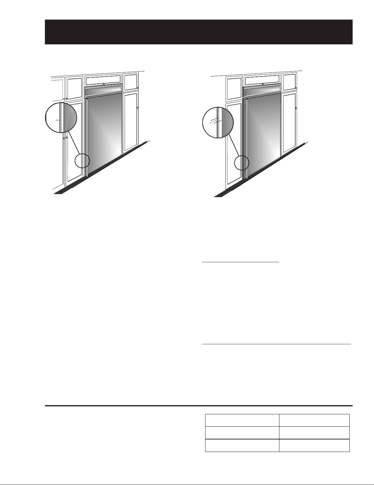
True Flush Installation
In a flush installation, the refrigerator doors
will align evenly with the front face of
adjacent cabinet doors. The refrigerator
blends into the surrounding cabinetry.
Monogram built-in refrigerators and freezers can
be installed flush with typical 24-3/4-in. deep
cabinetry.
When installed semi-flush, the case trim will
conceal slight gaps around the enclosure. The
refrigerator or freezer will project forward
approximately 3/4-in. beyond the front face of
surrounding cabinetry.
In any installation situation, a wide range of
appearance options can be accomplished through
the use of one or more trim kits. See trim kit
descriptions and appearance options in GE
Publication # 49-60055, Installation Instructions,
page 6.
GEA0066
Semi-Flush Installation
These refrigerators can also be installed
semi-flush into an enclosure using the
minimum cutout width. The case trim
creates a frame around the opening.
Side Panel Requirements:
• Side panels are not required whenever the
refrigerator is installed into an enclosure or
between pantry and oven cabinets.
• Side panels are required whenever the sides of
the refrigerator are exposed.
• Side panel sizes vary depending on the type of
installation being made.
To Accomplish an Attractive Installation, You Must:
1. Determine the need for side panels.
2. Determine side panel thickness.
3. Order matching side panels from the cabinet
manufacturer. Be sure to provide the exact
dimensions.
Caution: Maximum panel weight is 50 pounds.
When using custom panels, cut the grille panel
according to the following chart.
– 3 –
Leveling (Refrigerator and Freezer)
IMPORTANT: PLEASE READ CAREFULLY
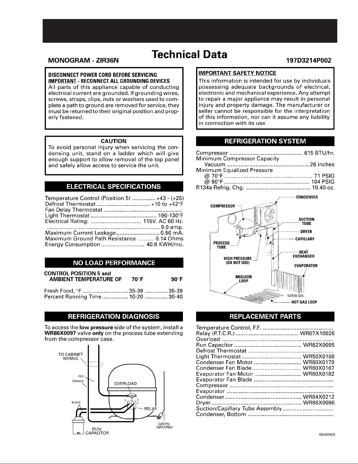
FOR PERSONAL SAFETY, THISAPPLIANCE MUST BE PROPERLY GROUNDED.
The power cord of this appliance is equipped with a three-prong (grounding) plug that mates with a standard three-prong (grounding) wall receptacle to minimize the
risk of electric shock hazard from this appliance. The customer should have the wall receptacle and circuit checked by a qualified electrician to make sure the receptacle
is properly grounded.
Where a standard two-prong wall receptacle is encountered, it is the personal responsibility and obligation of the customer to have it replaced with a properly grounded
three-prong wall receptacle.
DO NOT, UNDER ANY CIRCUMSTANCES, CUTOR REMOVE THE THIRD (GROUND) PRONG FROM THE POWER CORD.
USAGE
SITUATIONS WHERE THE APPLIANCE’S POWER CORD WILL BE DISCONNECTED INFREQUENTLY
Because of potential safety hazards under certain conditions, we strongly recommend against the use of an adapter plug. However, if you still elect to use an adapter,
where local codes permit, a TEMPORARY CONNECTION may be made to a properly grounded two-prong wall receptacle by the use of a UL listed adapter which is
available at most hardware stores. The larger slot of the adapter must be aligned to provide proper polarity in the connection of the power cord.
CAUTION: Attaching the adapter ground terminal to the wall receptacle cover screw does not ground the appliance unless the cover screw is metal, and not insulated,
and the wall receptacle is grounded through the house wiring. The customer should have the circuit checked by a qualified electrician to make sure the receptacle is
properly grounded. When disconnecting the power cord from the adapter, always hold the adapter with one hand. If this is not done, the adapter ground terminal is very
likely to break with repeated use. Should this happen, DO NOT USE the appliance until a proper ground has again been established.
USAGE
SITUATIONS WHERE THE APPLIANCE’S POWER CORD WILL BE DISCONNECTED FREQUENTLY
Do not use an adapter plug in these situations because frequent disconnecting of the power cord places undue strain on the adapter and leads to eventual failure of the
adapter ground terminal. The customer should have the two-prong wall receptacle replaced with a three-prong (grounding) receptacle by a qualified electrician before
using the appliance.
MAKE SURE PROPER
GROUND EXISTS
BEFORE USE
PREFERRED
METHOD
ENSURE PROPER
GROUND AND
FIRM CONNECTION
BEFORE USE
TEMPORARY METHOD
(Adapter plugs not
permitted in Canada)
197D3266P001 31-5087 9-00 JR
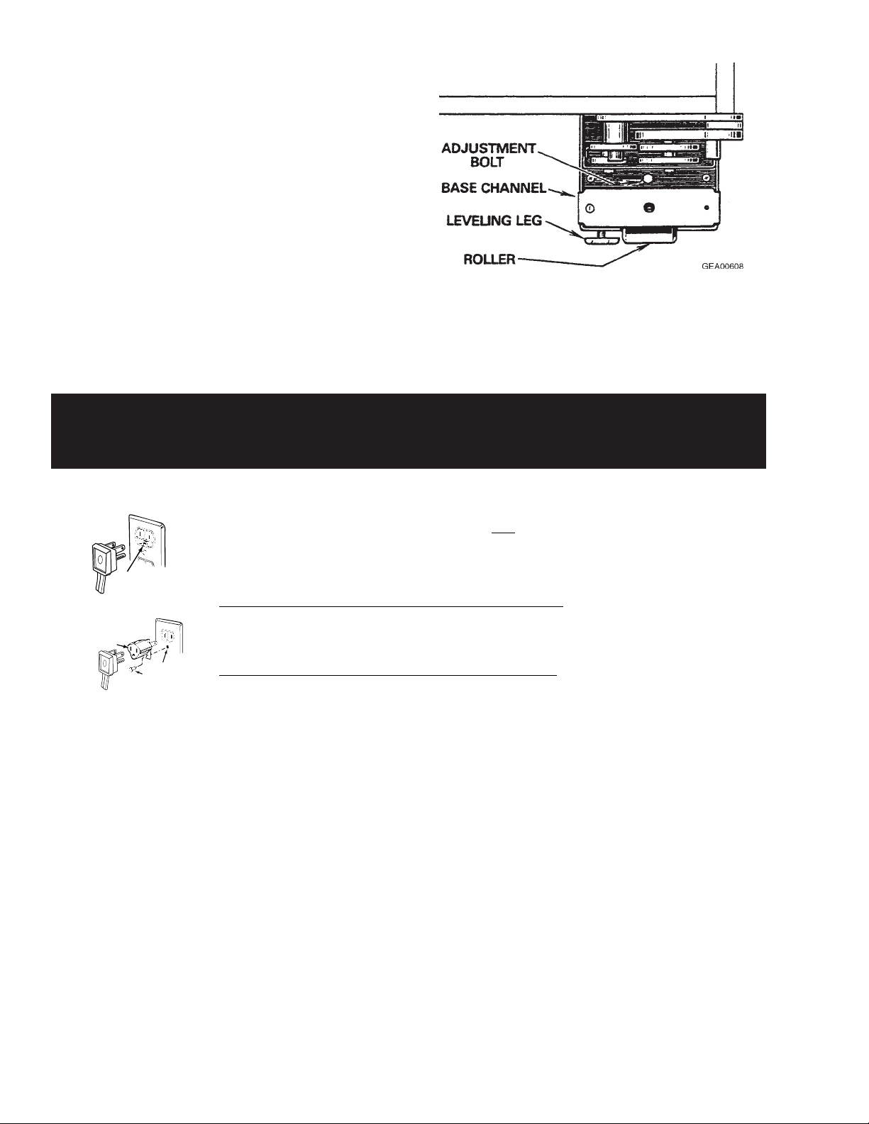
The unit must be level (zero tilt) from front to back
and from side to side. Rollers at the base of the
cabinet, near all four corners, aid the installer in
positioning the unit in its final location. The rear
rollers are adjustable, but the front rollers are nonadjustable.
1. To raise the rear of the cabinet, turn the 7/16in. hex head bolt, located in the base channel
near each front corner of the cabinet.
Note: Four full turns clockwise will raise the rear
roller approximately 3/16-in.
2. To level the front of the cabinet, adjust the
leveling legs at each front corner of the base
channel.
The plug in the wall receptacle is not accessible through the freezer machine compartment
because of the V -shaped condenser. To remove power from the freezer, disconnect the power
cord connector from the machine compartment electrical housing.
– 4 –
Specifications
– 5 –
– 6 –
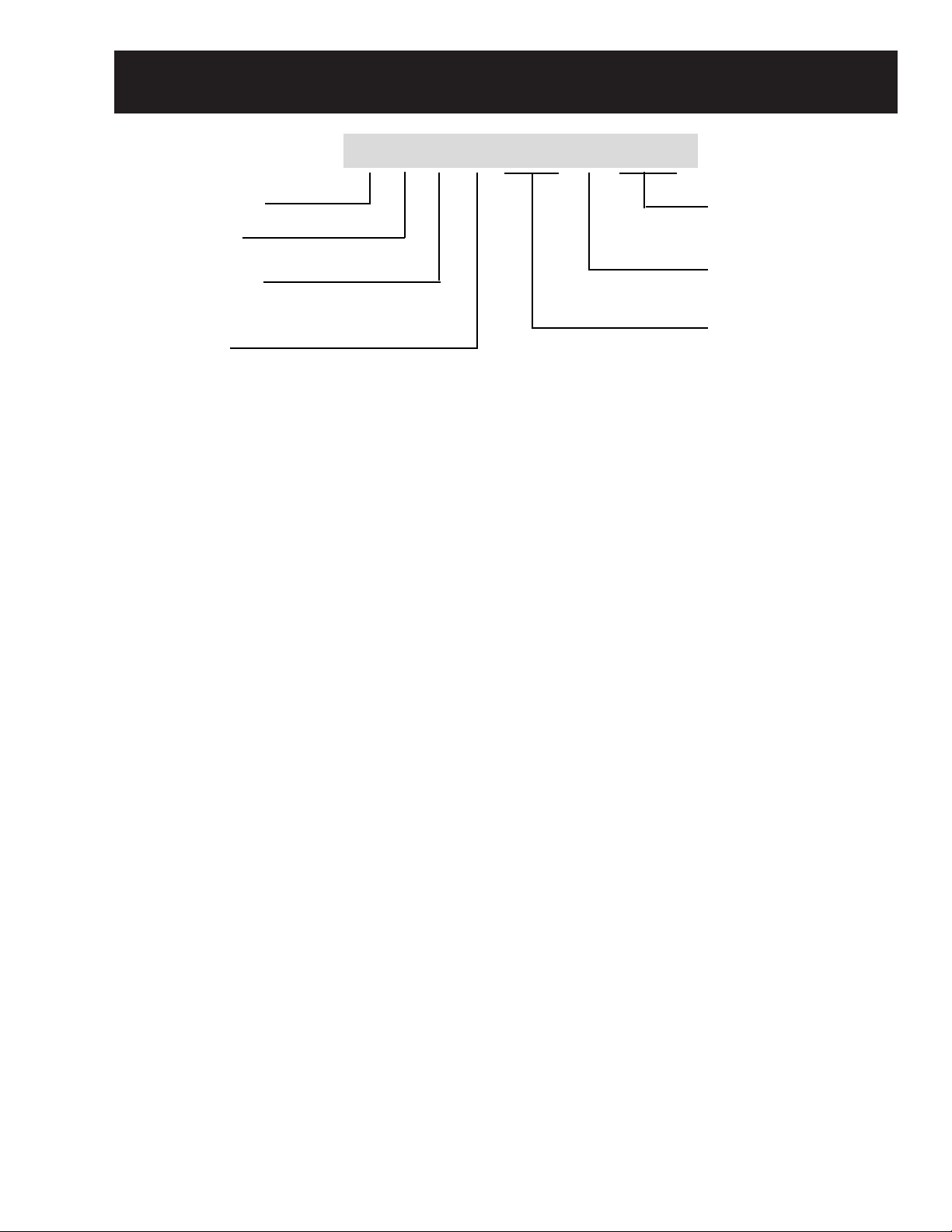
Nomenclature
r
Z I F S 3 6 N R H
GE Monogram
I = Built-in
Configuration
F = Freezer
R = Refrigerator
(Fresh Food)
Energy
S = Stainless Steel Model
Door Swing
RH = Right Hand
LH = Left Hand
Icemaker
N = GE Non-Icemake
Width (Inches)
– 7 –

Warranty Information
YOUR MONOGRAM WARRANTY
Staple sales slip or cancelled check here. Proof of original purchase
date is needed to obtain service under warranty.
WHAT IS
COVERED
From the Date
of the Original
Purchase
FULL TWO-YEAR WARRANTY
For two years from date of original purchase, we will provide, free of charge, parts and service labor in
your home to repair or replace any part of the refrigerator/freezer that fails because of a manufacturing
defect.
FULL FIVE-YEAR WARRANTY
For five years from date of original purchase, we will provide, free of charge, parts and service labor
in your home to repair or replace any part of the sealed refrigerating system (the compressor, condenser,
evaporator and all connecting tubing) that fails because of a manufacturing defect.
LIMITED ADDITIONAL SEVEN-YEAR WARRANTY ON THE SEALED SYSTEM
For the sixth through twelfth year from the date of the original purchase, we will provide, free of
charge, replacement parts for any part of the sealed refrigerating system (the compressor, condenser,
evaporator and all connecting tubing) that fails because of a manufacturing defect. You pay for
the service trip to your home and for service labor charges.
LIMITED LIFETIME WARRANTY ON ACCURIDE® SLIDES
From the date of the original purchase we will provide, free of charge, replacement parts for
any part of the Accuride Slides that fails because of a manufacturing defect. You pay for the service
trip to your home and for service labor charges.
This warranty is extended to the original purchaser and any succeeding owner for products
purchased for ordinary home use in the 48 mainland states, Hawaii and Washington, D.C.
In Alaska the warranty is the same except that it is LIMITED because you must pay to ship
the product to the service shop or for the service technician’s travel costs to your home.
All warranty service will be provided by our Factory Service Centers or by our authorized Customer
Care® servicers during normal working hours.
Should your appliance need service, during warranty period or beyond, in the U.S.A. call
800.444.1845.
Some states do not allow the exclusion or limitation of incidental or consequential damages, so the
above limitation or exclusion may not apply to you. This warranty gives you specific legal rights, and
you may also have other rights which vary from state to state. To know what your legal rights are in
your state, consult your local or state consumer affairs office or your state’s Attorney General.
Warrantor: General Electric Company. If further help is needed concerning this warranty, write:
Manager—Customer Relations, GE Appliances, Louisville, KY 40225
WHAT IS NOT
COVERED
• Service trips to your home to teach you how to
use the product.
Read your Use and Care material.
If you then have any questions about operating
the product, please contact your dealer or our
Customer Relations office at the address below,
or call, toll free:
GE Answer Center®
800.626.2000
consumer information service
• Replacement of house fuses or resetting of
circuit breakers.
• Damage to the product caused by accident, fire,
floods or acts of God.
• Failure of the product if it is used for
other than its intended purpose or used
commercially.
• Improper installation.
If you have an installation problem, contact
your dealer or installer. You are responsible for
providing adequate electrical, plumbing and
other connecting facilities.
• Loss of food due to spoilage.
WARRANTOR IS NOT RESPONSIBLE FOR
CONSEQUENTIAL DAMAGES.
– 8 –
Notes
– 9 –

Operating Characteristics
Note: Refer to Component and Connector
Locator Views.
• Refer to Schematics and Strip Circuits.
Component Description
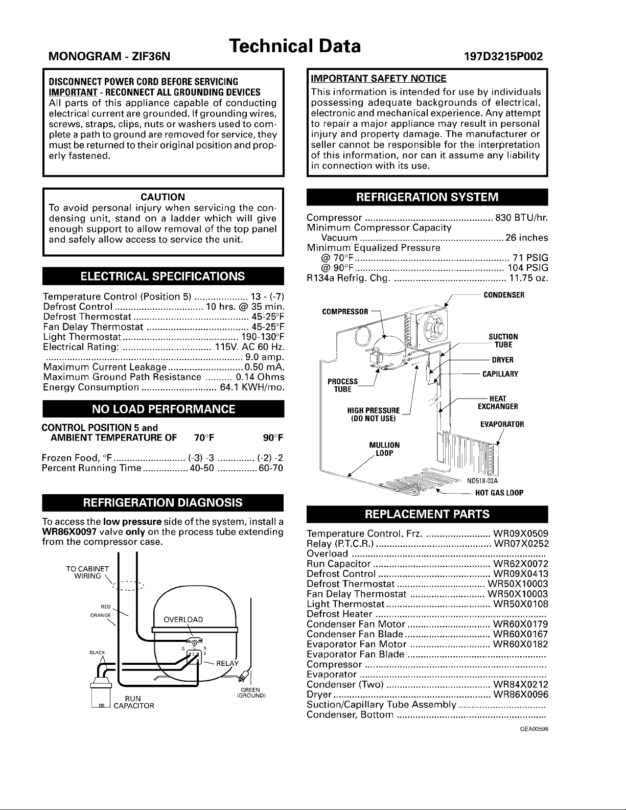
The compressor, dryer, and condenser are
located in the machine compartment on the top of
the cabinet. The evaporator is located on the
inside of the cabinet at the bottom of the back wall.
The capillary is soldered to the compressor
suction line. This arrangement serves as a heat
exchanger . The temperature control is located in
the top of the inside of the cabinet. The evaporator
fan is also located in the top of the inside of the
cabinet, behind the temperature control.
Electrical Operation (Freezer)
115V is provided from the power source to the
temperature control. The temperature control is a
thermostatic switch that closes when cabinet
temperature is higher than the control setting.
When closed, the temperature control provides
115V to the defrost control. The defrost control
contains a motor/cam mechanism that switches
the defrost control between defrost mode and
cooling mode. When in cooling mode, the defrost
control provides 115V to the compressor and to
the condenser fan. The condenser fan and
compressor always operate at the same time. In
addition to the compressor and condenser fan, the
defrost control provides 115V (in cooling mode)
through the cabinet door switch (evaporator fan
circuit) to the evaporator fan delay switch. The
door switch opens the evaporator fan switch
circuit when the cabinet door is open. The
evaporator fan delay switch opens when the
evaporator temperature has raised to 45°F and
closes when the evaporator temperature has
lowered to 25°F. When closed, the cabinet door
switch and evaporator fan delay switch provide
115V to the evaporator fan.
Electrical Operation (Refrigerator)
115V is provided from the power source to the
temperature control. The temperature control is a
thermostatic switch that closes when cabinet
temperature is higher than the control setting.
When closed, the temperature control provides
115V to the drain pan fan and defrost thermostat
switch. When closed, the defrost thermostat
switch provides 115V to the compressor and to
the condenser fan. The condenser fan and
compressor always operate at the same time.
115V is also provided from the power source to
the evaporator fan. The door switch opens the
evaporator fan switch circuit when the cabinet
door is open.
Air Movement
The cabinet is designed so that when the
evaporator fan is operating, air is drawn through
the evaporator and then up the back of the cabinet
through two ducts. At the top of the cabinet, the air
is drawn out of the ducts and through the
evaporator fan into the upper rear duct. Air moves
out of the upper rear duct and into the main part of
the cabinet. In the main part of the cabinet, the
cold air falls into the lower part of the cabinet and
is drawn into the evaporator again.
– 10 –
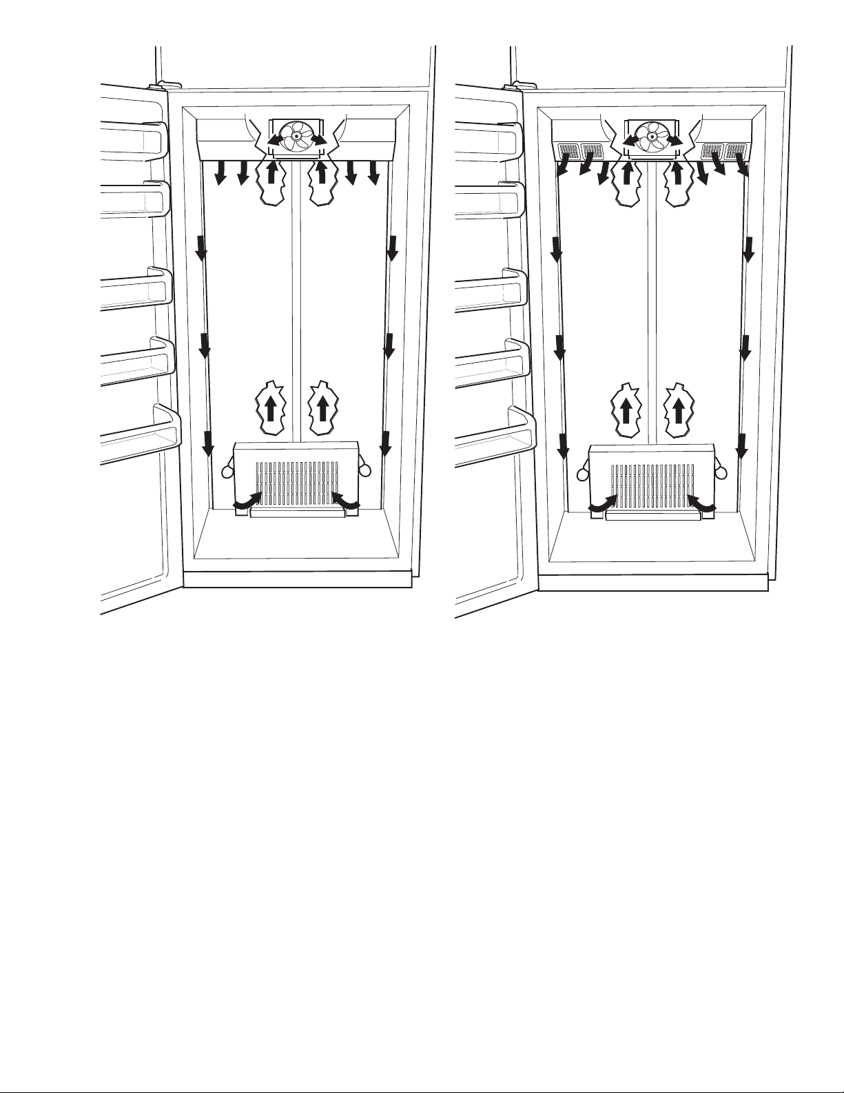
Refrigerator Air Flow
GEA00637
Freezer Air Flow
GEA00860
– 11 –
Notes
– 12 –

Mechanical Disassembly
Table of Contents
Door Handle (Refrigerator and Freezer) .............................................................. 15
Door Gasket (Refrigerator and Freezer)
Door Hinges (Refrigerator
Upper Door Hinge ............................................................................................. 15
Door Closure Mechanism.................................................................................15
Lower Door Hinge ............................................................................................. 16
Door Adjustment............................................................................................... 16
Door Assembly (Refrigerator
Icemaker (Freezer) .................................................................................................17
Icemaker Water V alve and W ater Line (Freezer)...................................................17
T o Replace the W ater V alve............................................................................... 17
T o Replace the Water Line from the
Water V alve to the Fill Tube Grommet......................................................... 18
and
Freezer) .............................................................. 15
and
................................................................15
Freezer) ......................................................... 16
Upper Light Shield (Refrigerator
Control Panel (Refrigerator
Upper Light Assembly (Refrigerator and Freezer)
Rear Duct (Refrigerator and Freezer)
T emperature Control (Refrigerator
Evaporator Fan (Refrigerator
and
Freezer) ...................................................19
and
Freezer) ............................................................ 19
................................................20
.....................................................................20
and
Freezer)
and
Freezer) ......................................................... 21
...................................................20
– 13 –

Storage Bin (Refrigerator
To Remove Only the Storage Bin......................................................................22
To Remove Both the Storage Bin and
the Bin Support ............................................................................................. 22
To Remove the Showcase Lid ........................................................................... 22
and
Freezer) ................................................................ 22
Storage Bin Slide Support and Center Divider (Refrigerator and Freezer) ...........
To Remove the Left or Right Slide Support .....................................................22
To Remove the Center Divider .......................................................................... 23
Evaporator Cover (Refrigerator
Defrost Heater (Freezer Only)................................................................................23
Evaporator (Refrigerator
Drain Pan Fan (Refrigerator
Grille Panel (Refrigerator
Rocker Switches (Refrigerator
and
and
Freezer)
and
Freezer) .................................................................24
Only
)......................................................................... 24
Freezer)
and
...................................................................25
Freezer) ........................................................ 25
.........................................................23
22
Defrost Control (Freezer) ....................................................................................... 26
PTCR Relay/Overload Cover (Refrigerator and Freezer)
PTCR Relay (Refrigerator
Overload (Refrigerator
Run Capacitor (Refrigerator
Slide-Out Chassis (Refrigerator
and
Freezer)................................................................ 26
and
Freezer).....................................................................27
and
Freezer)............................................................ 27
and
Freezer) ...................................................... 27
........................................26
– 14 –
8
The plug in the wall receptacle is not accessible through the freezer machine compartment
because of the V-shaped condenser. To remove power from the freezer, disconnect the power
cord connector from the machine compartment electrical housing.
Door Handle (Refrigerator and Freezer)
1. Open door to 90 degrees.
2. Remove 6 Phillips screws from the full-length
aluminum handle.
GEA0061
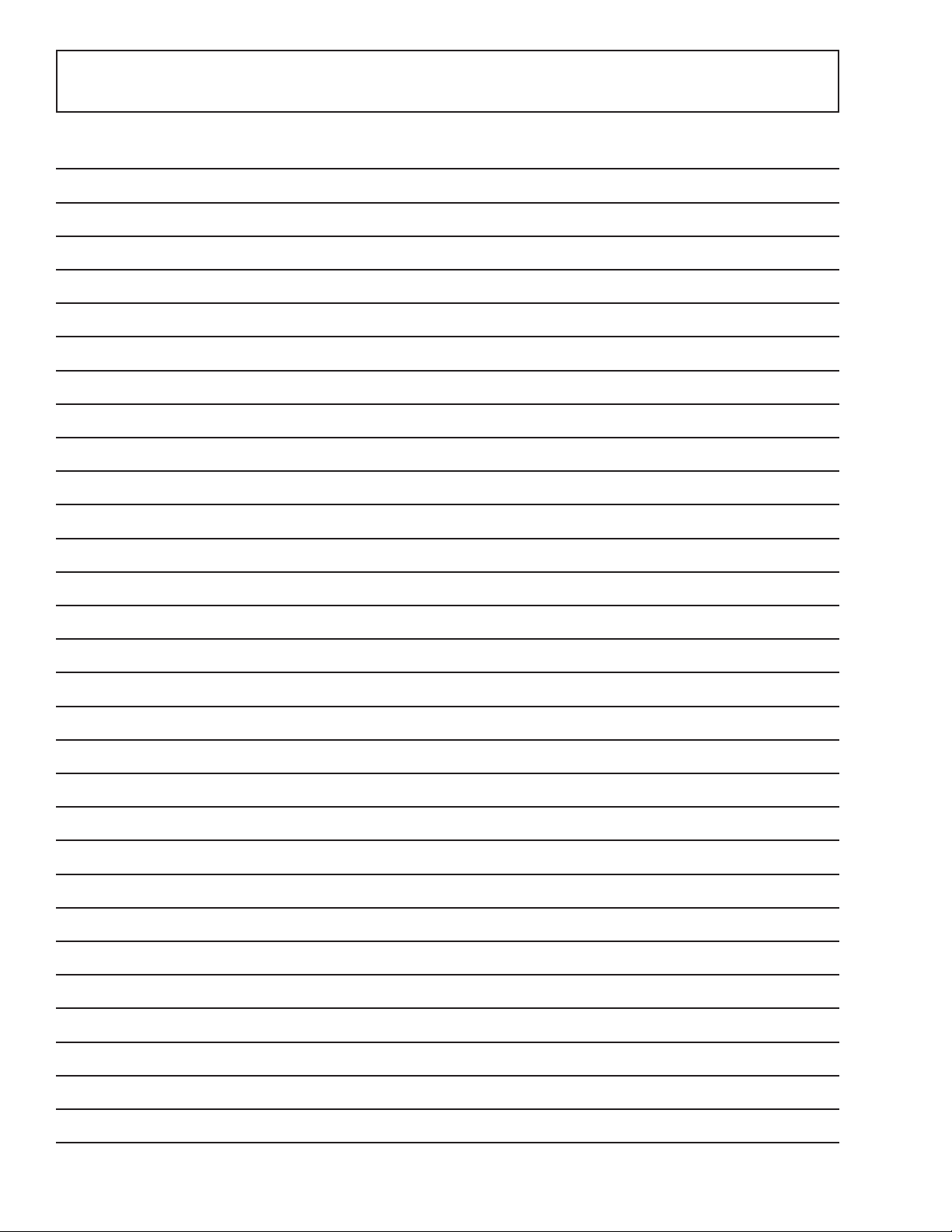
Door Gasket (Refrigerator and Freezer)
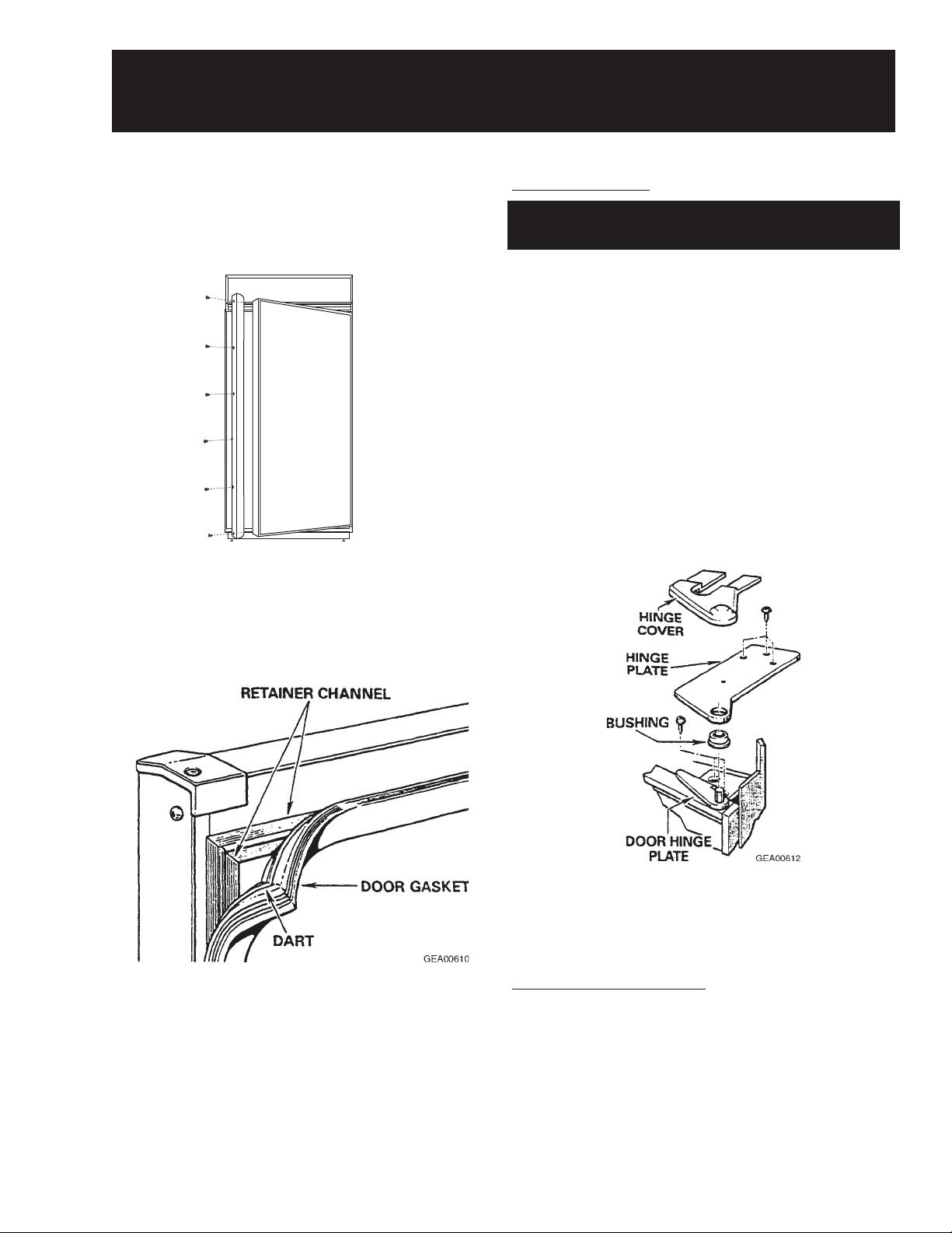
Door Hinges (Refrigerator and Freezer)
Upper Door Hinge
Note: There is no adjustment for the upper hinge
assembly.
1. Remove the grille panel (see page 25).
2. Remove 3 Phillips screws and the vent guard.
3. Carefully pry the wire guard above the hinge
upward by inserting a flat head screwdriver
between the bottom edge of the wire guard and
the hinge.
Note: The plastic hinge cover is held by doublesided adhesive tape.
4. Remove the hinge cover.
5. Remove T-20 Torx screws (3) securing the
upper hinge to the top of the cabinet.
Note: The door gasket is held in a retainer
channel.
1. Pull the old gasket out of the channel.
2. Soak the new gasket in warm water to make it
more pliable.
3. Using the back of a teaspoon, push the barbed
edge of the gasket into the retaining channel.
Note: The inner door panel is foamed in place and
is available only as a complete assembly with the
exterior door panel.
6. Remove the hinge and bushing.
7. Remove T -20 Torx screws (4) and the hinge
from the door .
Door Closure Mechanism
The door closure mechanism uses a spring to
provide positive door closure from 30 degrees. The
door closure mechanism actuator arm has a
spring attached to the rear and is supported by
guide rollers on either side of the base channel.
The roller circumferences and the actuator arm
detents are matched for smooth operation. The
arm is attached to the door with an Allen head
shoulder bolt.
– 15 –
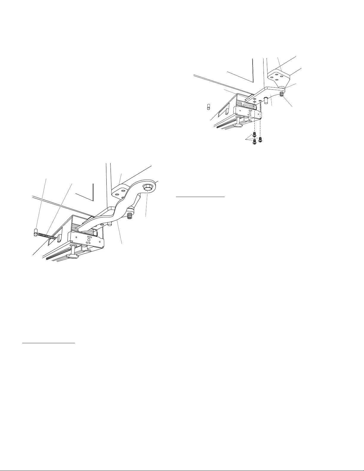
The closure mechanism allows easy opening to
4
3
g
B
approximately 90 degrees, where the arm has a
detent to permit the door to remain open at 90
degrees with minimal tension. Once the door is
opened beyond 90 degrees, the closure
mechanism pulls the door open until the closure
arm engages the door stop at approximately 140
degrees. The reverse action occurs when the door
is closed.
Note: Note the placement of spacers and washers
on the actuator arm for reassembly.
• The actuator arm is spring loaded with moderate
spring tension.
2. Remove T-20 Torx screws (3), base channel
spacer , and hinge from the underside of the
cabinet.
Hinge
ase Channel Spacer
Hinge
Bushin
Hinge
Pin
1. Remove the 5/16-in. bolt, washers, and spacer
from the door and actuator arm.
Door
Hinge
Pin
Spring
5/16"
Bolt
Actuator
Arm
GEA0066
2. Remove the icemaker water line from the door
closure mechanism (see page 17).
3. Remove 5 screws. The mechanism is now
loose from the cabinet.
4. Disconnect the spring from the pin on the
bottom of the cabinet.
Lower Door Hinge
1. Remove the door (see the following
procedure).
Note: Note the placement of spacers and washers
for reassembly.
Hinge
Screws
GEA0066
3. Remove T-20 Torx screws (4) fastening the
hinge to the bottom of the door .
4. Remove the hinge.
Door Adjustment
Be sure the top hinge does not hit the cabinet trim.
Adjust the door up or down by turning the threaded
hinge pin on the bottom hinge.
Door Assembly (Refrigerator and Freezer)
WARNING: The door assembly must be removed
by two people.
WARNING: Use the appropriate safety equipment
and lifting techniques.
Caution: Use wood or a heavy plastic sheet to
protect the floor where the door will be placed.
1. Remove all food and bins from the inner door
liner.
Note: Note the placement of spacers and
washers on the actuator arm for reassembly.
• The actuator arm is spring loaded with moderate
spring tension.
2. Remove the 5/16-in. bolt, washers, and spacer
from the door and actuator arm (see the
previous procedure for detailed art).
3. Remove the grille panel (see page 25).
4. Remove 3 Phillips screws from the vent guard.
5. Carefully pry the wire guard above the upper
hinge upward by inserting a flat head
screwdriver between the bottom edge of the
trim and the hinge.
– 16 –
Note: The plastic hinge cover is held by double-
6
6
sided adhesive tape.
4. Unplug the icemaker from the freezer wall and
remove.
6. Remove the hinge cover (see page 15 for
detailed art).
7. Remove T-20 Torx screws (3) securing the
upper hinge to the top of the cabinet.
8. Remove the upper hinge and bushing.
Note: Do not lose lower hinge bushing during
door removal.
9. Pull the top of the door outward until it clears
the top cabinet frame and carefully lift the door
off the lower hinge. Place door on the
protected floor area.
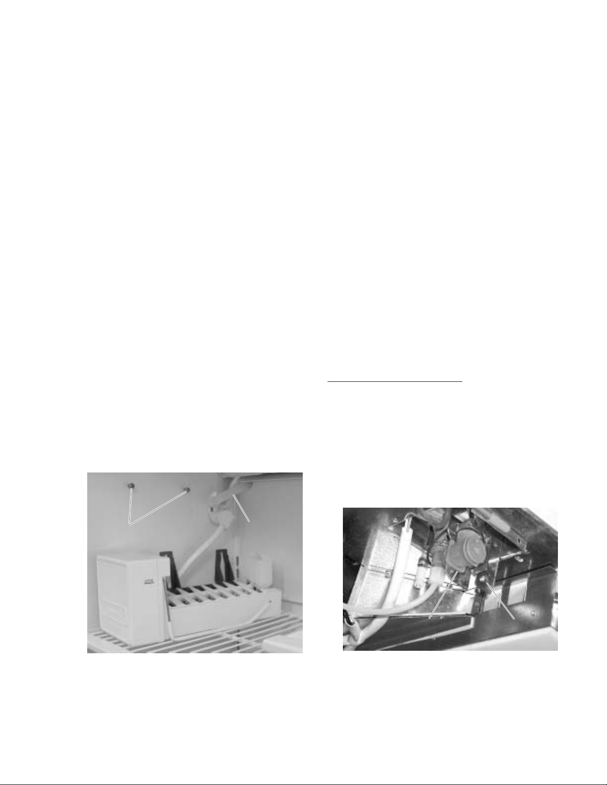
Icemaker (Freezer)
The icemaker is mounted to the upper left wall of
the freezer cabinet. Under normal operating
conditions, temperatures, door openings, and food
load, the icemaker is capable of producing
approximately 100 cubes in a 24 hour period.
1. Loosen 2 Phillips screws above the icemaker.
To service the icemaker, refer to GE Publication
31-4591, 1985 Icemakers.
Icemaker Water V alve and W ater Line
(Freezer)
The water valve is mounted under the cabinet,
beside the door closure mechanism. The valve has
a 1/4-in. stub of copper tubing to provide a
connection to the house water supply. Refer to GE
Publication # 49-60055, GE Monogram 36”
Refrigerators and 36” Freezers Custom
Options Guide and Installation Instructions for
connecting the freezer to the water supply.
A low-pressure plastic water line supplies water to
the icemaker from the water valve. The plastic
water line is routed from the water valve, under the
cabinet, through the back of the door closure
mechanism, and up the outside (back) of the
cabinet. At the top of the outside (back) of the
cabinet, the water line is connected to the fill tube
grommet. The icemaker fill tube is also plastic.
Caution: Use care to avoid damaging the water
tubing.
2. Slide the icemaker upward and pull off from the
screws.
3. Set the icemaker on the top freezer shelf.
ScrewsScrews
Water LineWater Line
GEA0062
To Replace the Water Valve:
Note: Some water may leak from the water supply
line and valve when they are disconnected.
1. Shut off the water supply to the freezer.
2. Remove the metal protective cover.
3. Remove 1 screw and lower the water valve
from the freezer .
ScrewScrewWater ValveWater Valve
GEA0066
– 17 –
 Loading...