

Monogram ZIRS360NXARH, ZIRS360NXALH, ZIR360NXALH, ZIF360NXARH, ZIFS360NXALH Installation Instructions Manual
...
Installation
Instructions
36" Built-In All-Refrigerators
and All-Freezers
31-/461/48
22/402601PO01
06-08 JR
monogram.com

Safet l Information
BEFORE YOU BEGIN
Read these instructions completely and carefully.
•IMPORTANT- Savetheseinstructions
forlocalinspector'suse.Observeallgoverning
codesand ordinances.
• Note to Installer - Be sure to leave these
instructions with the Consumer.
• Note to Consumer - Keepthese instructions
with your Owner's Manual for future reference.
AWARNING:
This appliance must be properly grounded.
See "Grounding the Unit," page 10.
AAVERTISSEMENT
Cet appareil doit @trecorrectement mis @laterre.
Consulter <<Mise@laterre de I'appareil m@nager >>,
page 10.
If you received a damaged product, you should
immediately contact your dealer or builder.
ACAUTION:
Due to the weight and size of this product, and to reduce
the risk of personal injury or damage to the product -
THREEPEOPLEAREREQUIREDFORPROPERINSTALLATION.
APRUDENCE
A cause du poids et de la taille de ce produit et
pour r@duirelerisque de blessure et de dommages,
IL FAUTTROISPERSONNESPOURFAIREL'INSTALLATION
CORRECTEMENT.
Skill Level -Installation of this product requires basic
mechanical, carpentry and plumbing skills. Proper
installation is the responsibility of the installer. Product
failure due to improper installation is not covered
under the GEAppliance Warranty. Seethe Owner's
Manualfor warranty information.
WARNING:
• These units are top-heavy and must be secured
to prevent the possibility of tipping forward. Anti-Tip
protection is required. See page 12 for details.
• Usethis appliance only for its intended purpose.
• Immediately repair or replace electric service cords
that become frayed or damaged.
• Unplug the unit before cleaning or making repairs.
• Repairsshould be made by a qualified service
technician.
AAVERTISSEMENT
• Ces appareils m@nagerssont Iourds en haut
et il faut les arrimer pour @viterleur basculement.
II faut avoir un syst@mede protection contre
le renversement. Voir les d@tailspage 12.
• IIne faut utiliser cet appareil que pour I'utilisation
appropri@e.
• R@parerou remplacer imm@diatement tout cordon
@lectriqueeffiloch@ou endommag@.
• IIfautd_brancherl'appareilm_nager avant
le nettoyage ou toute intervention.
• Lesr@parations doivent @trefaites par un technicien
qualifi&
For Monogram local service in gour area,
1.800.444.1845.
ForMonogram serviceinCanada
1.800.561.3344
ForMonogram Partsand Accessories,
call1.800.626.2002.
www.monogram.com
CONTENTS
Design Guide
TheInstallationSpace ......................................3
Dimensionsand Clearances......................3-4
130° Door Swing..................................................5
90°DoorSwing....................................................6
CustomizationBasics........................................7
PanelDimensions................................................8
SidePanels..............................................................9
ZUG2GrillePanelDimensions......................9
Installation Instructions
Tools, Hardware, Materials ..........................10
Grounding the Unit ..........................................10
Step 1,Remove Packaging ..........................11
Step 2, Install Water Line ............................11
Step 3, Install Side Panels ............................11
Step 4, Install Anti-Tip Bracket ..........12-14
Step 5, Level Unit ..............................................15
Step 6, Secure Unit to Wall ..........................16
Step 7, Adjust Door Swing ..........................17
Step 8, Install Grille Panel ............................17
Step 9, Install Framed Panels ....................18
Step 9A, Install Overlay Panels ................19
Step 10,Connect Water Supply ................20
Step 11, Start Icemaker ................................20
Step 12, Install Toekick ..................................20
Design Guide
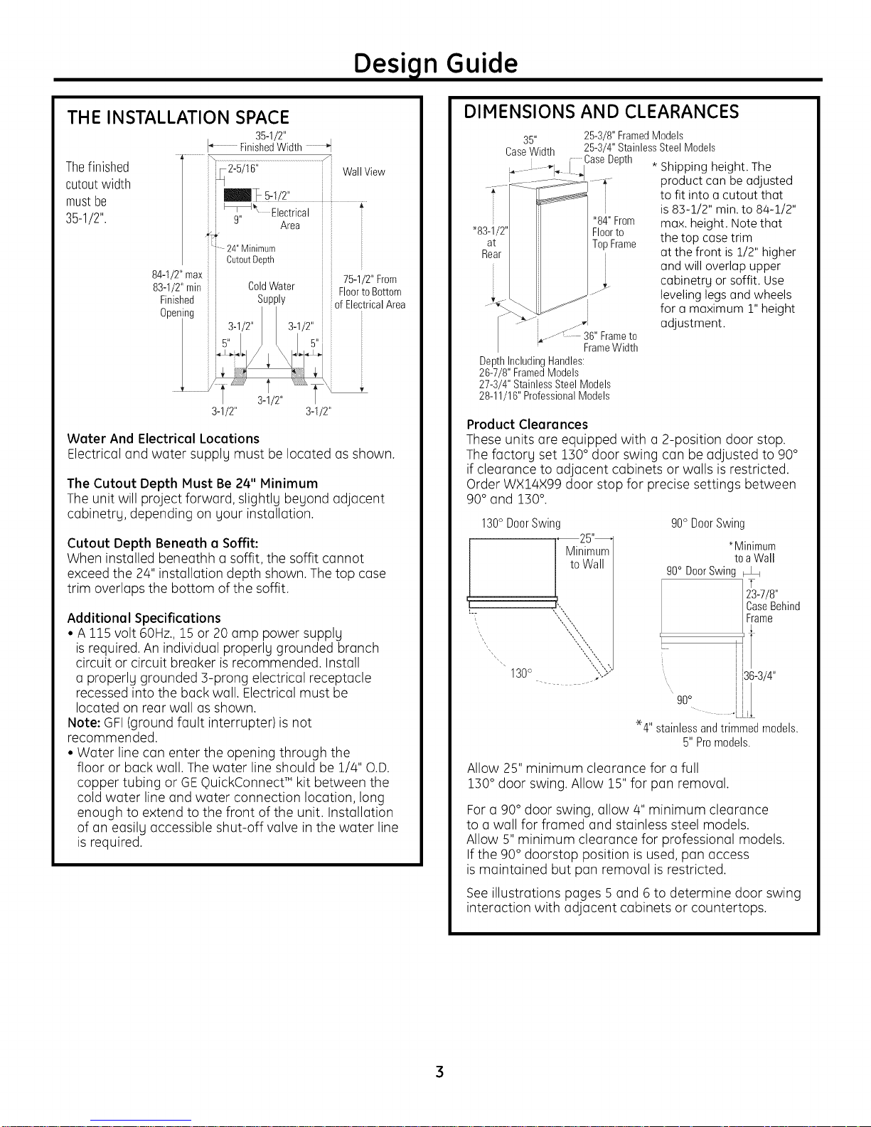
THE INSTALLATION SPACE
I_ FinishedWidth "t
Thefinished _ 2-5/16" Wall View
cutoutwidth
mustbe j _ 5:!!2:
35-1/2". j l_l_ Electrical
84-1/2"max
Water And Electrical Locations
Electrical and water supplg must be located as shown.
The Cutout Depth Must Be 24" Minimum
The unit will project forward, slightlg beyond adjacent
cabinetrg, depending on gour installation.
Cutout Depth Beneath a Soffit:
When installed beneathh a soffit, the soffit cannot
exceed the 24" installation depth shown. The top case
trim overlaps the bottom of the soffit.
Additional Specifications
• A 115volt 60Hz., 15 or 20 amp power supplg
is required. An individual properl9 grounded branch
circuit or circuit breaker is recommended. Install
a properl9 grounded ]-prong electrical receptacle
recessed into the back wall. Electrical must be
located on rear wall as shown.
Note: GFI(ground fault interrupter)is not
recommended.
• Water line can enter the opening through the
floor or back wall. The water line should be 1/4" O.D.
copper tubing or GEQuickConnect T"kit between the
cold water line and water connection location, long
enough to extend to the front of the unit. Installation
of an easilg accessible shut-off valve in the water line
is required.
35-1/2"
"1
] g" Area
24"Minimum i
Cutout Depth J
3-1/2" 3-1/2"
i
DIMENSIONS AND CLEARANCES
35"
CaseWidth
_°°} j.-vi
DepthIncludingHandles:
26-7/8" FramedModels
27-3/4" StainlessSteelModels
28-11/16" ProfessionalModels
Product Clearances
These units are equipped with a 2-position door stop.
The factorg set 1]0 ° door swing can be adjusted to 90°
if clearance to adjacent cabinets or walls is restricted.
Order WX14X99 door stop for precise settings between
90° and 1]0 °.
130° DoorSwin(
7
130°
Allow 25" minimum cleoronce for o full
1]0 ° door swing. Allow 15" for pon removal.
For o go° door swing, allow 4" minimum clearance
to o woll for fromed ond stoinless steel models.
Allow 5" minimum cleoronce for professionol models.
If the 90° doorstop position is used, pon occess
is mointoined but pon removol is restricted.
See illustrotions poges 5 ond 6 to determine door swing
interoction with odjocent cobinets or countertops.
25-3/8"FramedModels
25-3/4"StainlessSteelModels
CaseDepth * Shipping height. The
, product can be adjusted
"84"From max. height. Note that
Floorto the top case trim
TopFrame at the front is 1/2" higher
_. cabinetrg or soffit. Use
.........:: 36" Frameto
FrameWidth
25"--
Minimum
to Wall
to fit into a cutout that
is 83-1/2" min. to 84-1/2"
and will overlap upper
leveling legs and wheels
for a maximum 1" height
adjustment.
90° DoorSwing
90° DoorSwing
L
*4" stainlessandtrimmedmodels.
*Minimum
to aWall
i i
i
i
i l
'/
l i
i 136-3/4"
5" Promodels.
13_7/8,,
CaseBehind
F/ame
3
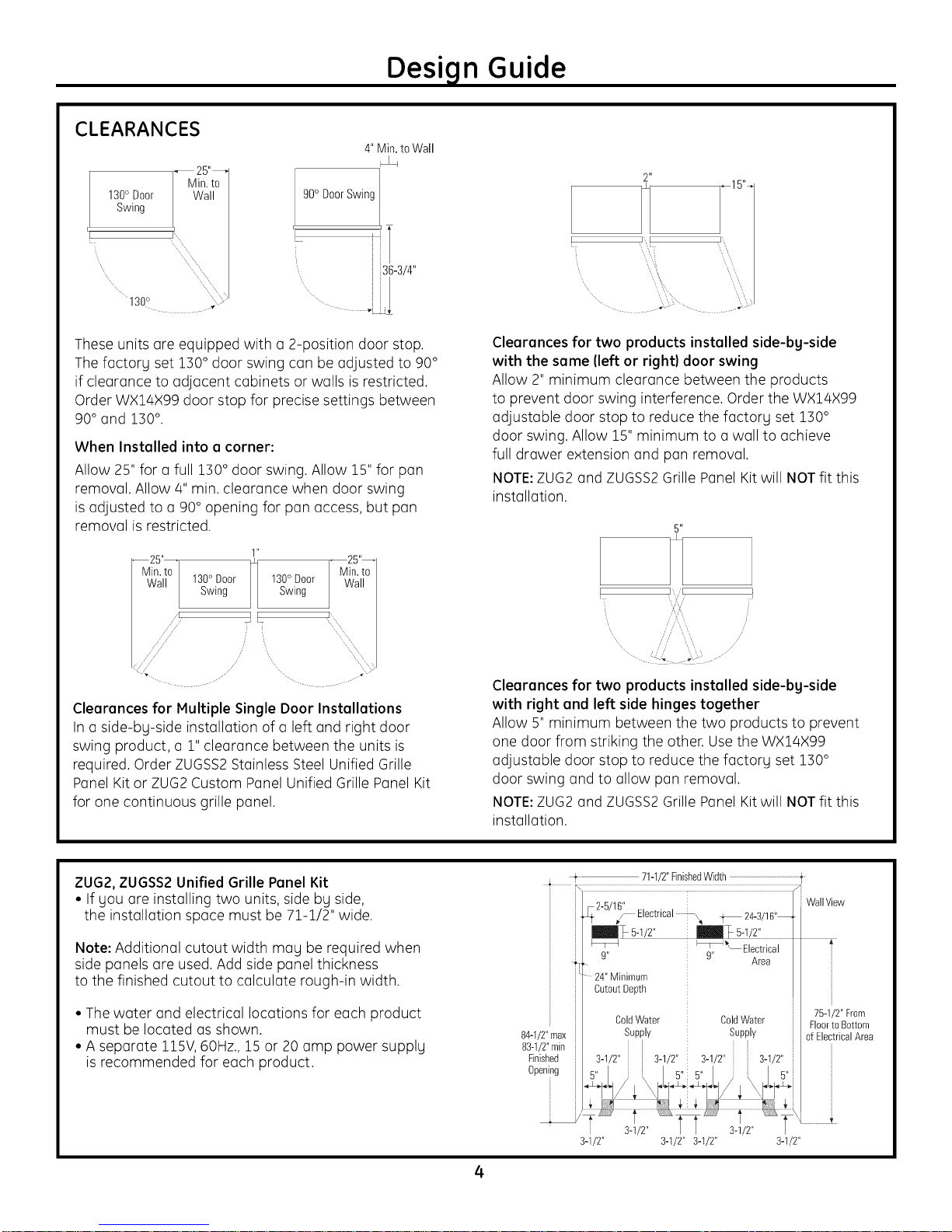
CLEARANCES
Design Guide
4" Min. to Wall
130° Door
Swing
.....130° .........
Ii to
0 DoorSwing
z
36-3/4"
.L
These units are equipped with a 2-position door stop.
The factory set 1]0 ° door swing can be adjusted to 90°
if clearance to adjacent cabinets or walls is restricted.
Order WX14X99 door stop for precise settings between
90° and 1]0 °.
When Installed into a corner:
Allow 25" for a full 1]0 ° door swing. Allow 15" for pan
removal. Allow 4" min. clearance when door swing
is adjusted to a 90° opening for pan access but pan
removal is restricted.
1"
130° Door 130° Door
Swing Swing
II I',
_L k'X
/ _, "k'X
25"
Min.to
Wall
2"
Fr i
Clearances for two products installed side-bg-side
with the same (left or right) door swing
Allow 2" minimum clearance between the products
to prevent door swing interference. Order the WX14X99
adjustable door stop to reduce the factory set 1]0 °
door swing. Allow 15" minimum to a wall to achieve
full drawer extension and pan removal.
NOTE:ZUG2 and ZUGSS2Grille Panel Kit will NOT fit this
installation.
5"
! i
'.... ,,"1%,
........:<i'L:
Clearances for Multiple Single Door Installations
In a side-by-side installation of a left and right door
swing product, a 1" clearance between the units is
required. Order ZUGSS2Stainless Steel Unified Grille
Panel Kit or ZUG2 Custom Panel Unified Grille Panel Kit
for one continuous grille panel.
ZUG2,ZUGSS2Unified Grille Panel Kit
• Ifyou are installing two units, side by side,
the installation space must be 71-1/2" wide.
Note: Additional cutout width may be required when
side panels are used. Add side panel thickness
to the finished cutout to calculate rough-in width.
• The water and electrical locations for each product
must be located as shown.
• A seporote llSV, 60Hz.,15 or 20 omp power supply
is recommended for each product.
Clearances for two products installed side-bg-side
with right and left side hinges together
Allow 5" minimum between the two products to prevent
one door from striking the other. Usethe WX14X99
adjustable door stop to reduce the factory set 1]0 °
door swing and to allow pan removal.
NOTE:ZUG2 and ZUGSS2Grille Panel Kit will NOT fit this
installation.
71-1/2"FinishedWid[h..............................................................t
WallView
24"Minimum
CutoutDepth
75-1/2" From
84-1/2"max
83-1/2"min
Finished
Opening
ColdWater ColdWater Floorto Bottom
Supply Supply ofElectricalArea
i
3-1/2" j 3-1/2" 3-1/T 3-1/2"
s" i 5" 5" i 5"
c............................ .................
' 3-1/2" _ 3-1/2" T
3-1/2" 3-1/2" 3-1/2" 3-1/2"
4
Design Guide
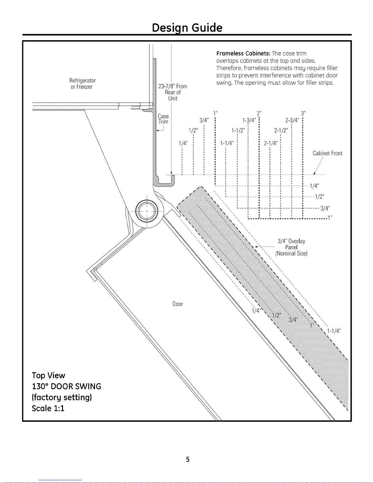
Refrigerator
or Freezer 23-7/8"From
Rearof
Unit
Frameless Cabinets: The case trim
overlaps cabinets at the top and sides.
Therefore, frameless cabinets mag require filler
strips to )revent interference with cabinet door
swing. The opening must allow for filler strips.
Case
Trim
1/4"
1/2"
i1_ 3"
3/4"
1-1/2"
21_
1-3/4"
2-1/4"1-1/4"
", 3/4"Overlay
", Panel
CabinetFront
/
Top View
130° DOOR SWING
(factorg setting)
Scale 1:1
Door
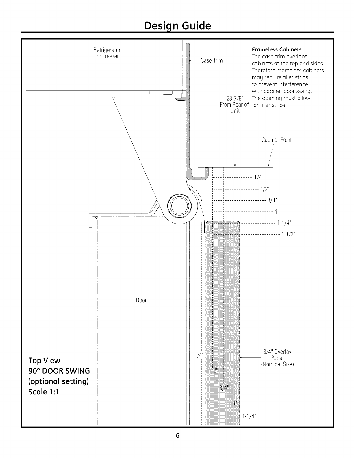
Design Guide
Refrigerator
or Freezer
CaseTrim
Frameless Cabinets:
The case trim overlaps
cabinets at the top and sides.
Therefore, frameless cabinets
mag require filler strips
to prevent interference
with cabinet door swing.
23-7/8" The opening must allow
FromRearof for filler strips.
Unit
Top View
90 ° DOOR SWING
(optional setting)
Scale 1:1
Door
6
CUSTOMIZATION BASICS:
Design Guide
Framed Or Overlag
Professional Stgle Stainless Steel Models
Stainless steel wrapped refrigerators have beveled edges
and professional-stgle handles. These models are shipped
readg for installation.
Stainless Steel Wrapped Models
Stainless Steelwrapped models have wrapped
doors and grille panel, beveled edges, and tubular
stainless steel handles that coordinate with other
Monogram appliances. These models are shipped
readg for installation.
Trimmed Models
Trimmed models are designed to be customized with
decorative panels. Field installed custom door and grille
panels are required.
Framed panels
You mag install 1/4" thick custom panels from
gour cabinet manufacturer. The decorative panel slides
into the factorg installed trim. Or,order black and stainless
steel accessorg panels from gour Monogram dealer.
Panels, Custom Handles and Accessorg Kits
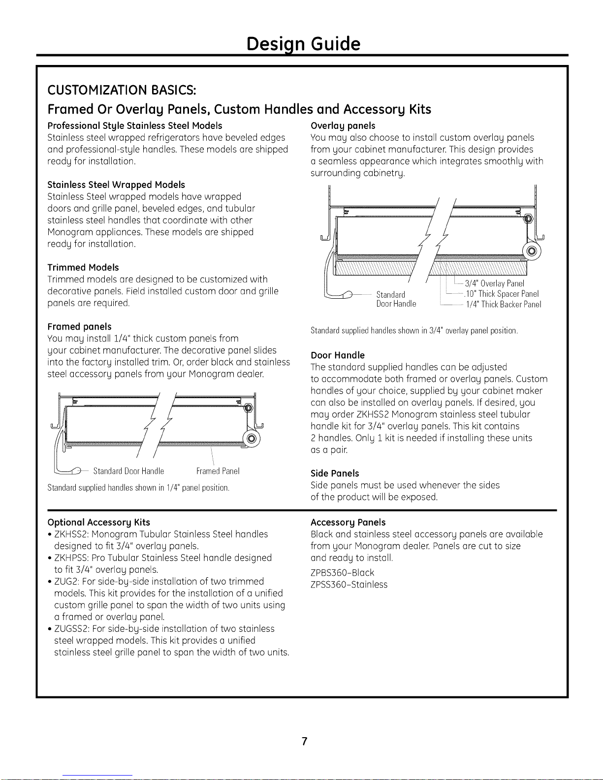
Overlag panels
You may also choose to install custom overlay panels
from gour cabinet manufacturer. This design provides
a seamless appearance which integrates smoothlg with
surrounding cabinetrg,
__ Standard
3/4"OverlayPanel
DoorHandle
Standardsuppliedhandlesshownin 3/4" overlaypanelposition.
Door Handle
The standard supplied handles can be adjusted
to accommodate both framed or overlag panels. Custom
handles of gour choice, supplied bg gour cabinet maker
can also be installed on overlag panels. If desired, gou
mag order ZKHSS2Monogram stainless steel tubular
handle kit for 5/4" overlag panels. This kit contains
2 handles. Onlg 1 kit is needed if installing these units
as a pair.
ii _ ......lO"ThickSpacerPanel
1/4"ThickBackerPanel
StandardDoorHandle FramedPanel
Standardsuppliedhandlesshownin 1/4" panelposition.
Optional Accessorg Kits
• ZKHSS2:Monogram Tubular Stainless Steel handles
designed to fit 3/4" overlag panels.
• ZKHPSS:ProTubular Stainless Steel handle designed
to fit 3/4" overlag panels.
• ZUG2: Forside-bg-side installation of two trimmed
models. This kit provides for the installation of a unified
custom grille panel to span the width of two units using
a framed or overlag panel.
• ZUGSS2:Forside-bg-side installation of two stainless
steel wrapped models. This kit provides a unified
stainless steel grille panel to span the width of two units.
Side Panels
Side panels must be used whenever the sides
of the product will be exposed.
Accessorg Panels
Black and stainless steel accessorg panels are available
from gour Monogram dealer. Panels are cut to size
and readg to install.
ZPBS560-Black
ZPSS360-Stainless
7
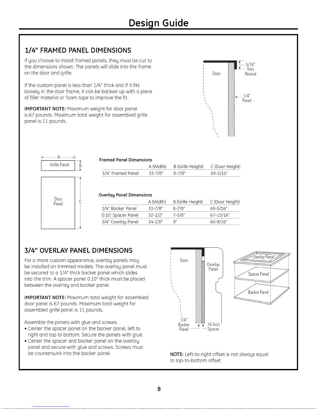
1/4" FRAMED PANEL DIMENSIONS
Design Guide
If you choose to install framed panels, they must be cut to
the dimensions shown. The panels will slide into the frame
on the door and grille.
If the custom panel is less than 1/4" thick and if it fits
loosely in the door frame, it can be backed up with a piece
of filler material or foam tape to improve the fit.
IMPORTANTNOTE:Maximum weight for door panel
is 67 pounds. Maximum total weight for assembled grille
panel is 11 pounds.
I_A_I
Framed Panel Dimensions
l GrillePanel ]_
1/4" Framed Panel 33-7/8" 8-7/8" 69-5/16"
Door
Panel
Overlag Panel Dimensions
1/4" Backer Panel 33-7/8" 8-7/8" 69-5/16"
0.10" Spacer Panel 32-1/2" 7-5/8" 67-15/16"
3/4" Overlay Panel 34-1/8" 9" 69-9/16"
n _ 5/16"
Door
A (Width) B (Grille Height) C (Door Height)
A (Width) B (Grille Height) C (Door Height)
Trim
Reveal
1/4"
Panel
314" OVERLAY PANEL DIMENSIONS
Fora more custom appearance, overlay panels may
be installed on trimmed models. The overlay panel must
be secured to a 1/4" thick backer panel which slides
into the trim. A spacer panel 0.10" thick must be placed
between the overlay and backer panel.
IMPORTANTNOTE:Maximum total weight for assembled
door panel is 67 pounds. Maximum total weight for
assembled grille panel is 11 pounds.
Assemble the panels with glue and screws.
• Center the spacer panel on the backer panel, left to
right and top to bottom. Secure the panels with glue.
• Center the spacer and backer panel on the overlay
panel and secure with glue and screws. Screws must
be countersunk into the backer panel.
Door
\\
1/4"
Backer _ , ch
Panel _ Spacer
NOTE:Left-to-right offset is not always equal
to top-to-bottom offset.
 Loading...