

Page 1

INSTALLATION
INSTRUCTIONS
18”, 24” and 30” Built-In Column Freezers
24” and 30” Built-In Column Refrigerators
ENGLISH/FRANÇAIS/ESPAÑOL.
MONOGRAM.COM
Page 2
Safety Information
BEFORE YOU BEGIN
Read these instructions completely and carefully.
IMPORTANT – Save these instructions for
•
local inspector’s use. Observe all governing codes and
ordinances.
Note to Installer – Be sure to leave these
•
instructions with the Consumer.
• Note to Consumer – Keep these instructions with
your Owner’s Manual for future reference.
If you received a damaged unit, you should immediately
contact your dealer or builder.
Skill Level – Installation of this unit requires basic
mechanical, carpentry and plumbing skills. Proper
installation is the responsibility of the installer. Product
failure due to improper installation is not covered under
the Monogram Warranty. See the Owner’s Manual for
warranty information.
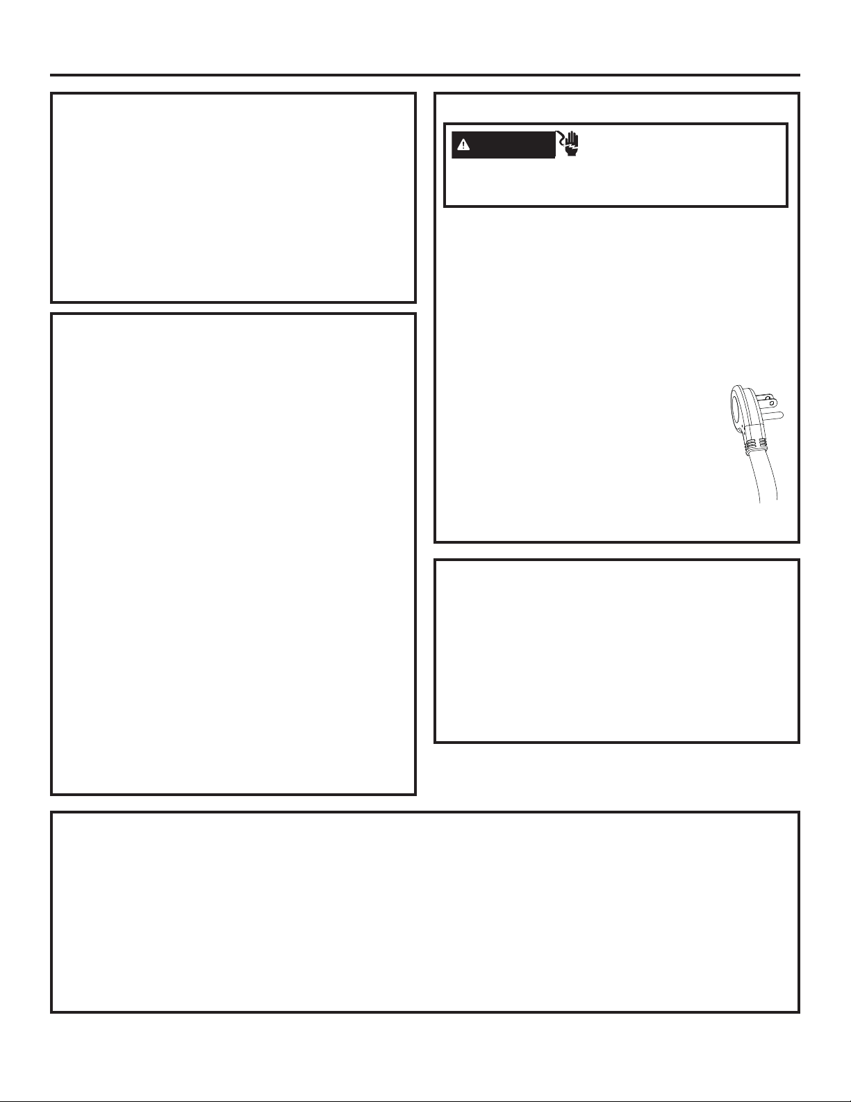
WARNING
Plug into a grounded 3-prong outlet.
Do not remove the ground prong.
Do not use an adapter.
Immediately discontinue use of a damaged supply cord.
If the supply cord is damaged it must be replaced by a
qualified service professional with an authorized service
part from the manufacturer.
WARNING
These appliances are top heavy, especially with any doors open, and must be secured to prevent tipping
forward which could result in death or serious injury. Read and follow the entire installation instructions for
securing the appliance with the anti-tip system.
WARNING
Keep flammable materials and vapors away from appliance. Failure to do so can result in fire, explosion,
or death.
WARNING
have access to small parts during the installation of this product.
Electrical Shock Hazard.
Do not use an extension cord with this appliance.
Failure to follow these instructions can result in death,
fire, or electrical shock.
Follow the instructions in the section Grounding the unit.
This appliance must be installed with a means in the fixed
house wiring or circuit breaker for disconnecting the appliance from the electrical supply after installation.
Tip Over Hazard.
Fire or Explosion Hazard.
To reduce the risk associated with choking, do not allow children under 3 years of age to
CAUTION
This unit is very heavy. To reduce the risk of person injury during maneuvering and installing this appliance,
3 people are required for proper installation.
CAUTION
doors and cabinet are necessarily small. Be careful closing doors when children are in the area.
For Monogram local service in your area, visit monogram.com or call 800.444.1845.
For Monogram service in Canada, visit monogram.ca or call 800.561.3344.
For Monogram Parts and Accessories, visit monogram.com or call 800.444.1845.
For Monogram Parts and Accessories in Canada, visit monogram.ca or call 800.661.1616.
Lifting Hazard
Keep fingers out of the “pinch point” areas; clearances between the doors and between the
2
31-1000190 Rev. 4
Page 3

Contents
Safety 2
Design Guide
Dimensions and Clearances 4
Accessories/Kits 5
Reversing the Door Swing 6
Step 1. Remove Upper Enclosure 7
Step 2. Remove Door 7
Step 3. Move Control Assembly 8
Step 4. Move Light Switch Housing 8
Step 5. Reinstall Hinge Brackets 9
Step 6. Reinstall the Enclosure 9
Step 7. Reinstall the Front Access Cover 10
Step 8. Remove Hinges from Door 10
Step 9. Panel Brackets and Hinges 11
Step 10. Reinstall the Door 11
Instructions for Dual Integrated Installation 12
The Installation Space 13
Tools, Hardware, Materials 14
Grounding the Unit 15
Flooring 15
Step 1. Remove Packaging 15
Step 2. Install Water Line 16
Step 3. Preparing Unit for Installation 16
Step 4. Install Anti-tip Bracket 17
Step 5. Joining Dual Installed Units 18
Step 6. Connecting Water Supply 19
Step 7. Inserting/Securing into Cabinet Surround 19
Step 8. Level Unit 20
Step 9. Final External Unit Preparation 21
Step 10. Toe Kick Installation 22
Step 11. Internal Unit Preparation 22
Step 12. Start Icemaker 22
Step 13. Install AutoFill Pitcher Assembly 23
Step 12. Start Icemaker 36
Step 13. Install AutoFill Pitcher Assembly 37
Instructions for Single Integrated Installation 38
The Installation Space 39
Tools, Hardware, Materials 40
Grounding the Unit 40
Flooring 40
Step 1. Remove Packaging 41
Step 2. Install Water Line 41
Step 3. Preparing Unit for Installation 42
Step 4. Install Anti-tip Bracket 42
Step 5. Connecting Water Supply 42
Step 6. Inserting/Securing into Cabinet Surround 43
Step 7. Level Unit 44
Step 8. Final External Unit Preparation 44
Step 9. Toe Kick Installation 45
Step 10. Internal Unit Preparation 45
Step 11. Start Icemaker 45
Step 12. Install AutoFill Pitcher Assembly 46
Stainless Steel Door Panel Installation 47
Step 1. Install Stainless Panel 48
Step 2. Adjust Stainless Panel 49
Step 3. Install Hinge Covers 49
Step 4. Install Door Trims 50
Custom Overlay Door Panel Installation 51
Custom Handle Design Guide 52
3/4” Custom Decorative Panel Dimensions 52
Step 1. Overlay Panel Prep 53
Step 2. Install Overlay Panel 54
Step 3. Adjust Overlay Panel 54
Step 4. Install Hinge Covers 55
Step 5. Install Door Trims 55
Instructions for Dual Retro-Fit Installation 24
The Installation Space 25
Tools, Hardware, Materials 26
Grounding the Unit 26
Flooring 26
Step 1. Remove Packaging 27
Step 2. Install Water Line 27
Step 3. Preparing Unit for Installation 28
Step 4. Install Anti-tip Bracket 29
Step 5. Joining Dual Installed Units 30
Step 6. Connecting Water Supply 32
Step 7. Inserting/Securing into Cabinet Surround 33
Step 8. Level Unit 34
Step 9. Final External Unit Preparation 34
Step 10. Toe Kick Installation 36
Step 11. Internal Unit Preparation 36
31-1000190 Rev. 4
3
Page 4
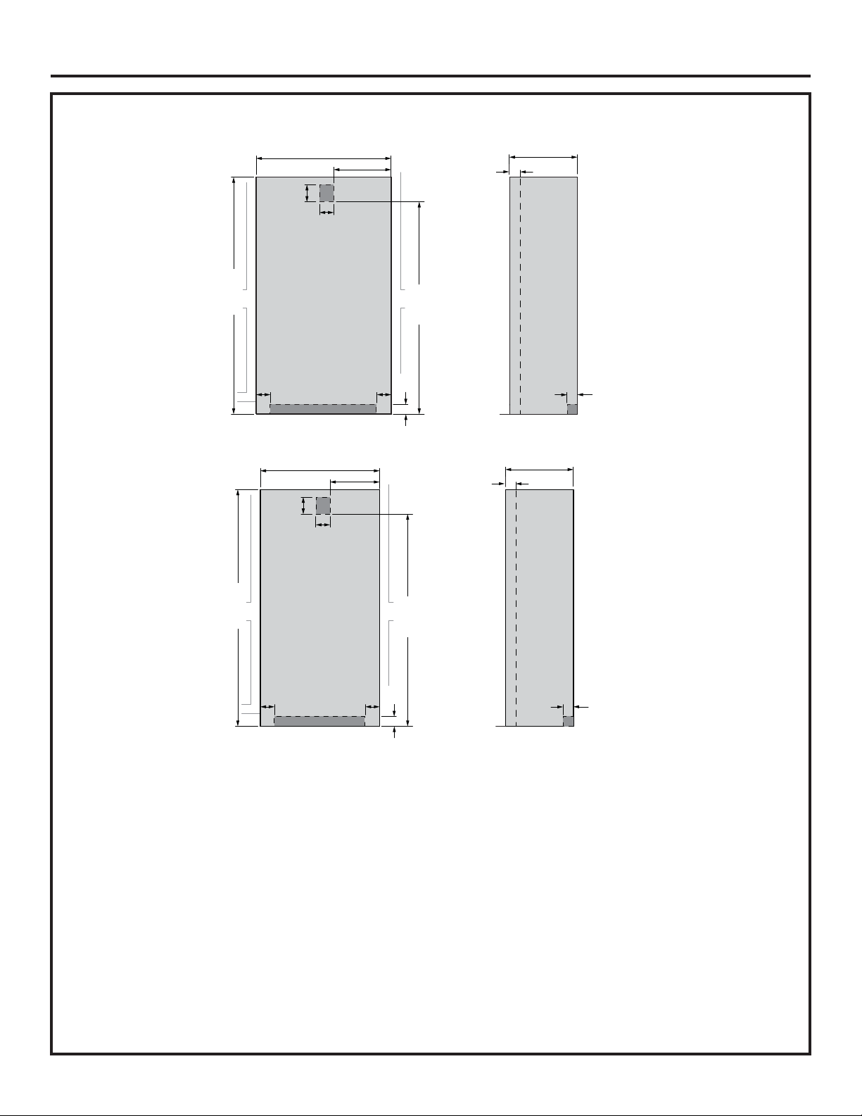
Design Guide
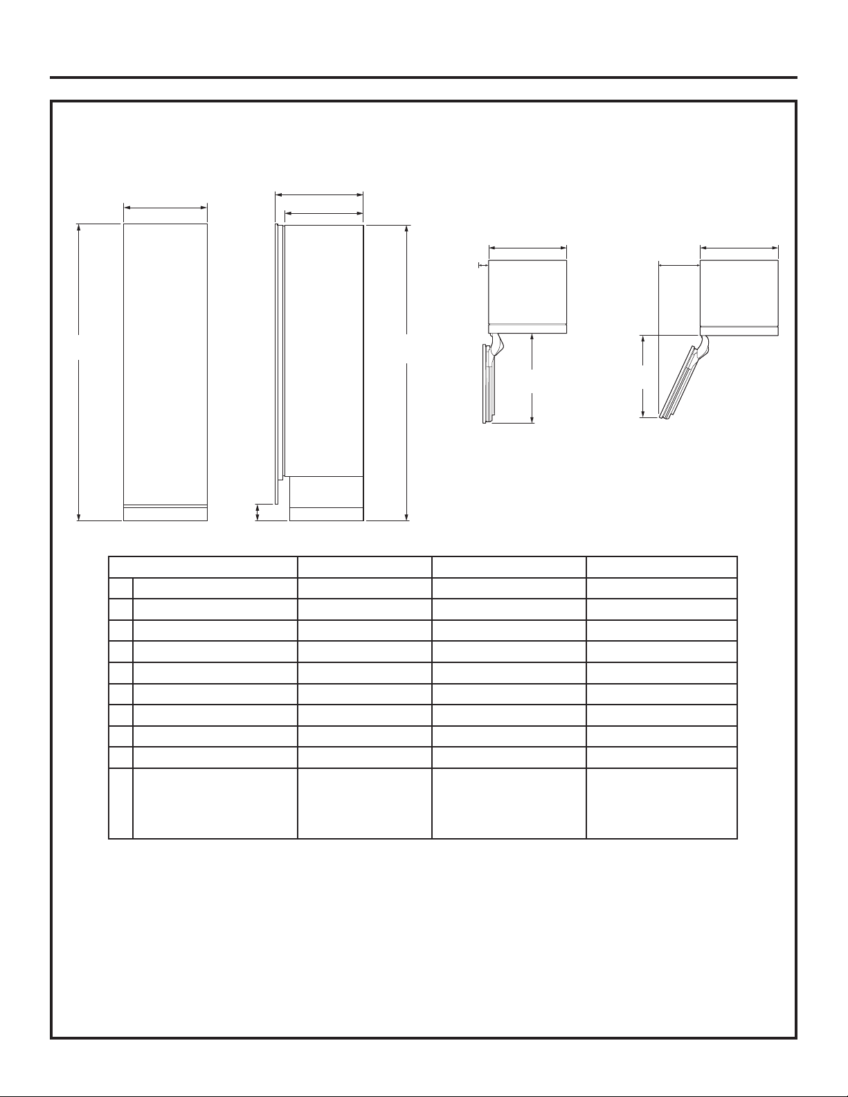
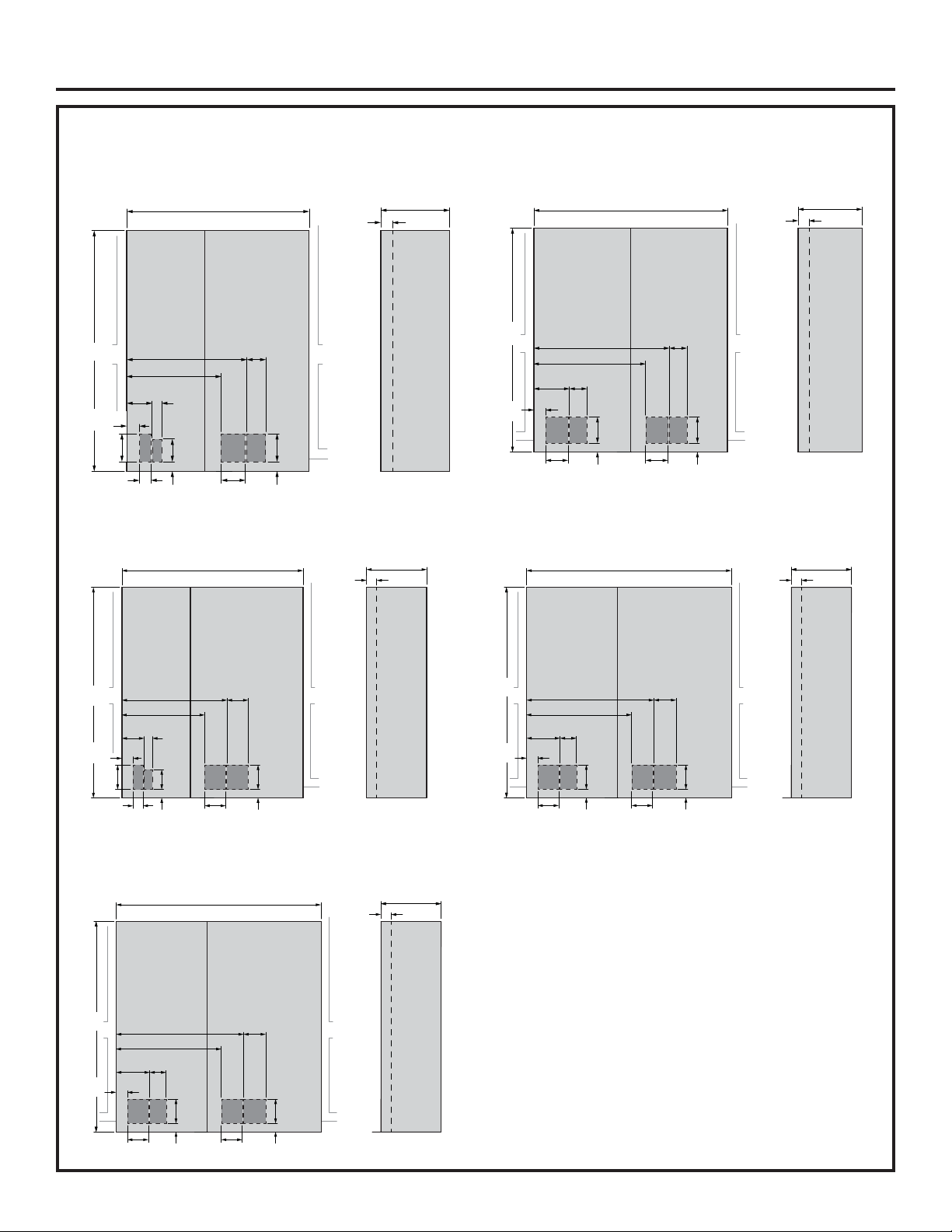
DIMENSIONS AND CLEARANCES
Dimensions in parentheses are in centimeters.
Overall Dimensions
83-3/8"
(211.77)
A
4"
(10.16)
FRONT VIEW SIDE VIEW
C
D
TOP VIEWS
(38.1)
15"
Minimum
to a Wall
(42.1)
(16-9/16"
on 30” models)
F
Û DOOR OPEN 115Û
83-1/4"
(211.46)
5-1/8"
(13.0)
Minimum
to a Wall
B
E
DOOR OPEN 90
DIMENSIONS BASED ON HANDLE
HEIGHT OF 2-9/16” (6.5)
Dimensions 18” Models 24” Models 30” Models
A Overall Width - Front 17-1/2” (44.5 cm) 23-1/2” (59.7 cm) 29-1/2” (74.9 cm)
B Overall Width - Rear 17-1/4” (43.8 cm) 23-1/4” (59.1 cm) 29-1/4” (74.3 cm)
C Overall Depth 24-3/4” (62.9 cm) 24-3/4” (62.9 cm) 24-3/4” (62.9 cm)
D Case Depth 22-1/16” (56 cm) 22-1/16” (56 cm) 22-1/16” (56 cm)
E Door Clearance at 90° 21-1/4” (53.9 cm) 27-1/4” (62.9 cm) 33-1/4” (84.5 cm)
F Door Clearance at 115° 19-1/16” (48.4 cm) 24-1/2” (62.2 cm) 29-15/16” (76.0 cm)
Cutout Width 17-13/16” (45.3 cm) 23-13/16” (60.5 cm) 29-13/16” (75.7 cm)
Cutout Height 84” (213.4 cm) 84” (213.4 cm) 84” (213.4 cm)
Cutout Depth 25” (63.5 cm) 25” (63.5 cm) 25” (63.5 cm)
Weight 370 lbs
(167.8 kg)
460 lbs (208.7 kg)
(Refrigerator)
430 lbs. (195.0 kg)
(Freezer)
495 lbs (224.5 kg)
(Refrigerator)
475 lbs. (215.5 kg)
(Freezer)
B
Shipping height.
The product can be adjusted to fit into a cutout that is
84” (213.36 cm). Use leveling legs and wheels for a
maximum 1” (2.54 cm) height adjustment.
Product Clearances
These units are equipped with a 2-position door stop.
The factory set 115° door swing can be adjusted to 90°
if clearance to adjacent cabinets or walls is restricted.
For a 90° door swing, allow 4” (10.2 cm) minimum
clearance to a wall.
When installed in a corner, allow 15” (38.1 cm) for a full
115° door swing on 18” and 24” models. Allow 16 9/16”
(42.07 cm) on 30” models.
4
31-1000190 Rev. 4
Page 5
Design Guide
7KH0RQRJUDP&ROXPQVUHIULJHUDWRUVDQGIUHH]HUVFDQEHLQVWDOOHGLQPDQ\FRQ¿JXUDWLRQVZLWKGLႇHUHQWLQVWDOODWLRQ
situations. Three installation situations will be explained along with door reversal instructions and two options for door
panel installation.
Reversing the Door Swing (all installation types)
Making a refrigerator LH swing and freezer RH swing. MUST be done BEFORE the unit is removed from the shipping skid.
Instructions for Dual Integrated Installation
New construction installation with 25” deep openings
Instructions for Dual Retro Installation
Existing construction installation (existing cutouts) with 24” deep openings that are 41-1/2” or 47-1/2” wide
Instructions for Single Integrated Installation
New construction installation with 25” deep opening
Instructions for Stainless Steel Door Panel Installation (all installation types)
Installing Stainless Steel Door Panel Kits
Instructions for Custom Overlay Door Panel Installation (all installation types)
Installing Custom Decorative Panels
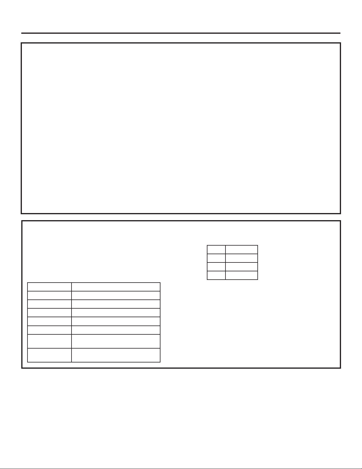
ACCESSORIES/KITS
Ŷ ZKUN+HDWHU8QL¿FDWLRQ.LW
Ŷ WX08X10006 8 Ft. Water Line
Ŷ ZKR42N 42” Trim Retro Kit
Ŷ ZKR48N 48” Trim Retro Kit
Ŷ 6WDLQOHVV6WHHO'RRU3DQHO.LWV
ZK1SN189NLH LH 18” Stainless Steel Door Panel
ZK1SN184NRH RH 18” Stainless Steel Door Panel
ZK1SN249NLH LH 24” Stainless Steel Door Panel
ZK1SN244NRH RH 24” Stainless Steel Door Panel
ZK1SN309NLH LH 30” Stainless Steel Door Panel
ZK1SN304NRH RH 30” Stainless Steel Door Panel
ZKSP1H1CNSS Minimalist Handle for Stainless
Steel Panels Only
ZKSP1H1PNSS Statement Handle for Stainless
Steel Panels Only
Ŷ 6WDLQOHVV7RH.LFNVIRU'XDO,QVWDOO
42” ZKK42P
48” ZKK48P
54” ZKK54P
60” ZKK60P
31-1000190 Rev. 4
5
Page 6

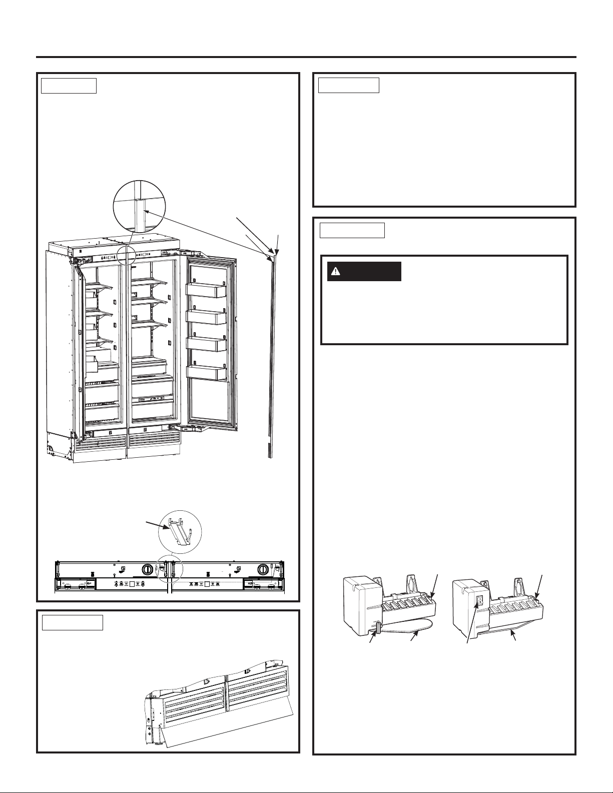
Reversing the Door Swing
This step can be done for all installation types.
6
31-1000190 Rev. 4
Page 7
Installation Instructions - Reversing the Door Swing
WARNING
door swing. Failure to follow these instructions, leaving
off parts, or overtightening screws, can lead to the door
falling off and result in injury and property damage.
Ŷ If installation will require the door swing to be reversed,
follow these directions to reverse the door swing
BEFORE the unit is removed from the shipping skid.
Ŷ Instructions for reversing a RH swing refrigerator are
shown in the following steps.
WARNING
This appliance is top heavy, especially with the door
open, and must be secured to prevent tipping forward
which could result in death or serious injury.
Follow all steps when reversing the
Tip Over Hazard.
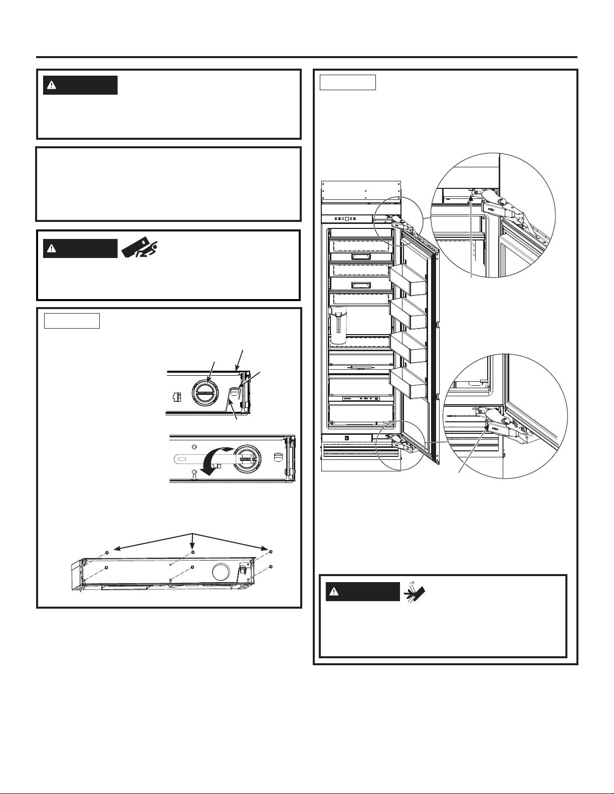
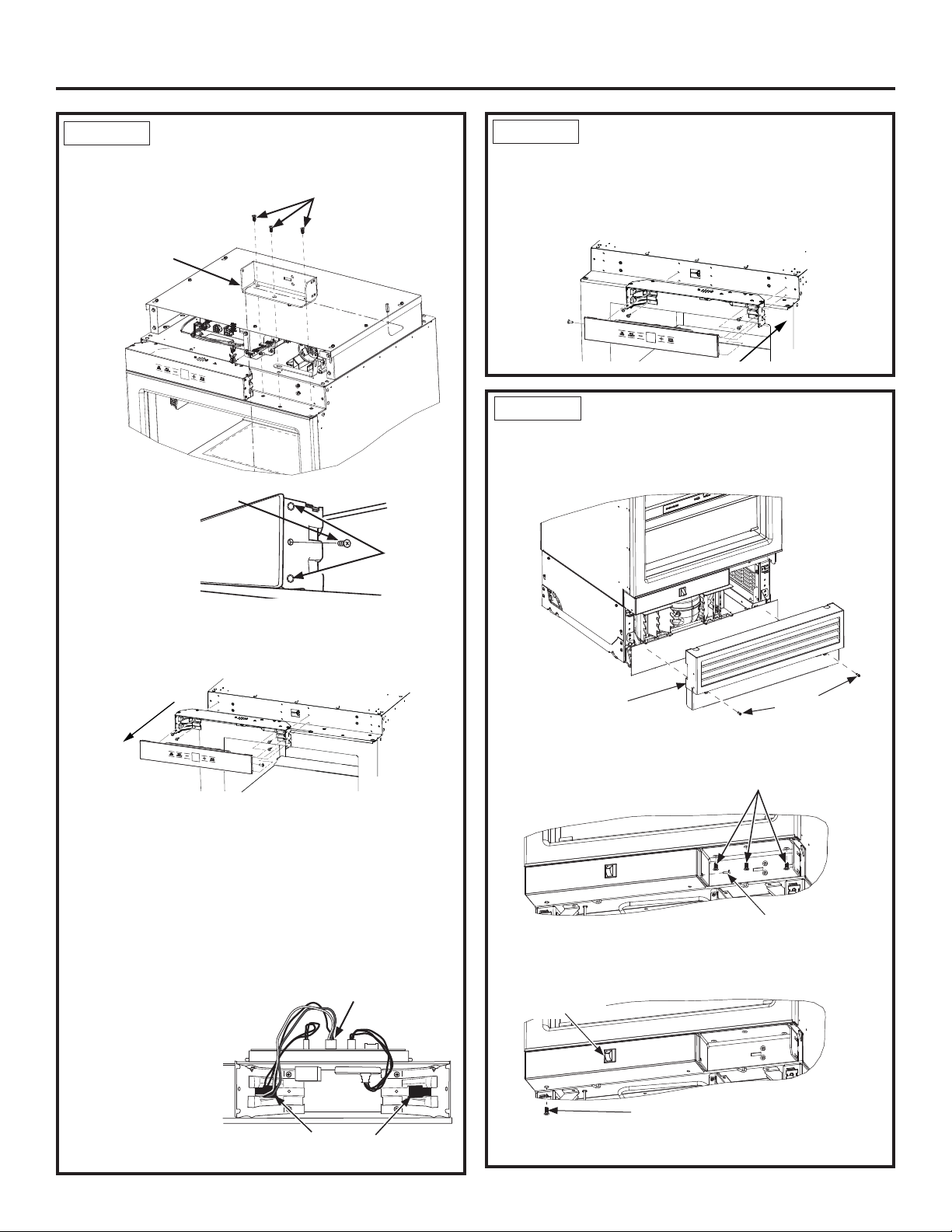
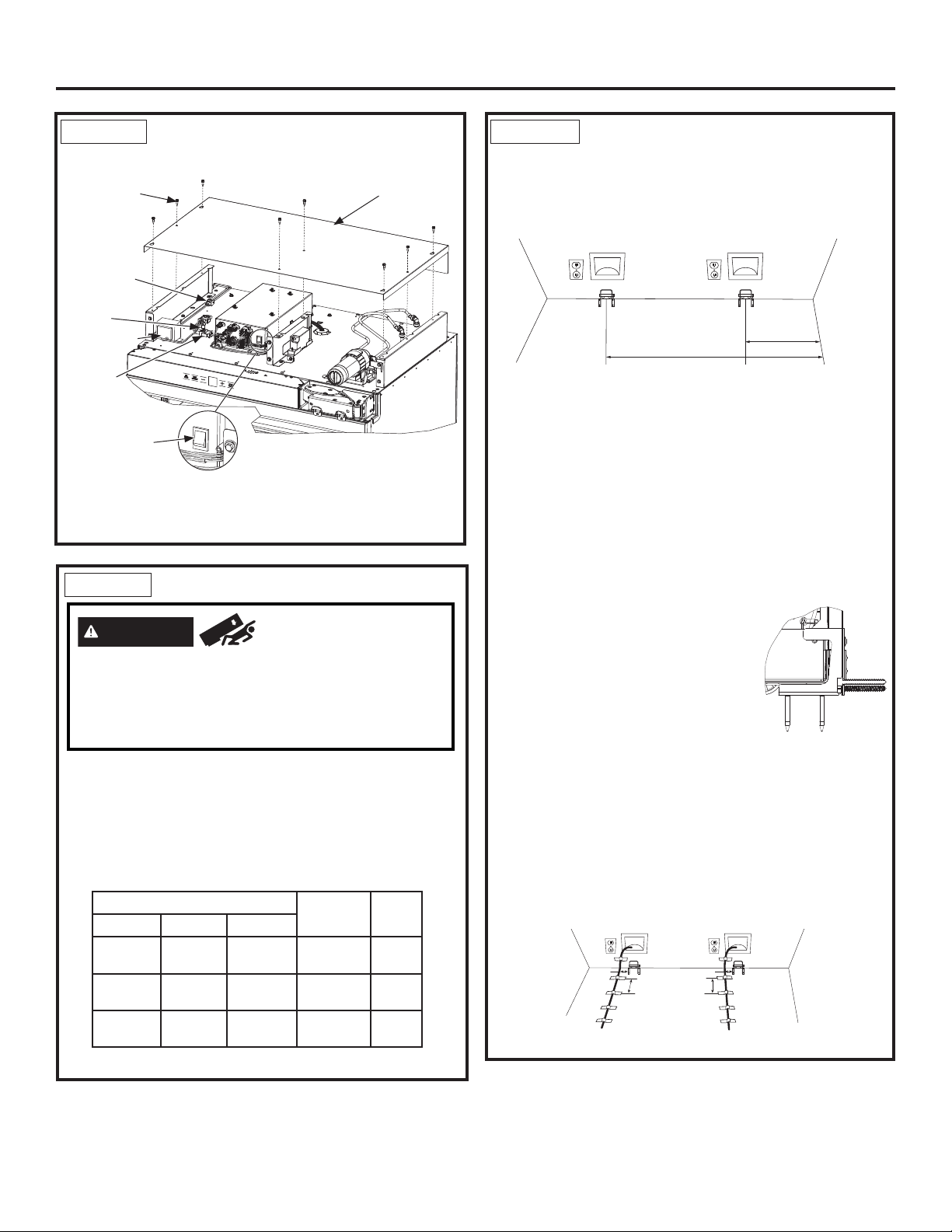
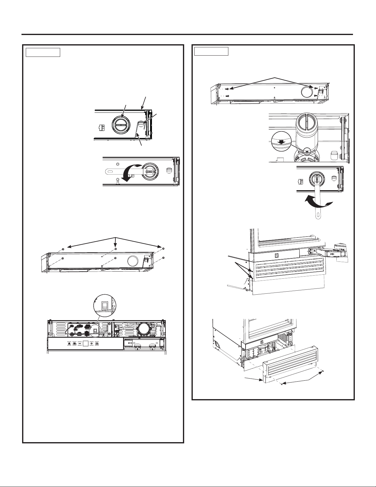
STEP 1 REMOVE UPPER
ENCLOSURE
Ŷ Open the front cover of
the enclosure to 90°.
Locate filter and filter
removal tool. Filter
should be as shown.
Ŷ5RWDWH¿OWHUóWXUQ
counterclockwise
XVH¿OWHUUHPRYDOWRROLI
needed).
Ŷ3XOO¿OWHUWRZDUG\RXWR
remove. NOTE: Water
V\VWHPZLOOQRWIXQFWLRQZLWKRXW¿OWHULQSODFH
Ŷ Remove 6 screws securing front enclosure to top case.
1/4” Hex Screws
Compartment Door
Filter
Mounting
Hook
Filter Removal Tool
STEP 2 REMOVE DOOR
Ŷ Open the door to the open position.
Ŷ Have a second person support the open door.
Ŷ Remove 2 T30 Torx screws securing the bottom
hinge to the case.
Screws
Screws
Ŷ Remove the 2 T30 Torx screws securing the top
hinge to the case.
Ŷ Place the door on a protected work surface (to
prevent scratches), liner side down.
NOTICE: Door hinges will remain in the open position
during the door reversal procedure.
31-1000190 Rev. 4
WARNING
Door Hinge Pinch
Point Hazard
Door hinges are under tension and should be left in the
open position throughout the reversal process. Closing
the hinge can lead to a finger pinch point hazard.
7
Page 8
Installation Instructions - Reversing the Door Swing
STEP 3
Ŷ Remove upper hinge brackets by removing the T-30
Torx screws.
Ŷ Remove the
Phillips head
screw from the
middle of the
housing on the
hinge side.
Ŷ Insert a flat head screwdriver or putty knife between
the glass front and plastic side and free the control
assembly by prying the plastic pins clear of the side
bracket holes.
MOVE CONTROL ASSEMBLY
T-30 Torx screws
Upper Hinge
Bracket
Screw
Plastic Pins
(Both sides)
STEP 3
MOVE CONTROL ASSEMBLY
(Cont.)
Ŷ Snap glass assembly back onto the control housing
assembly, ensuring plastic pins snap into holes on
the side of the housing.
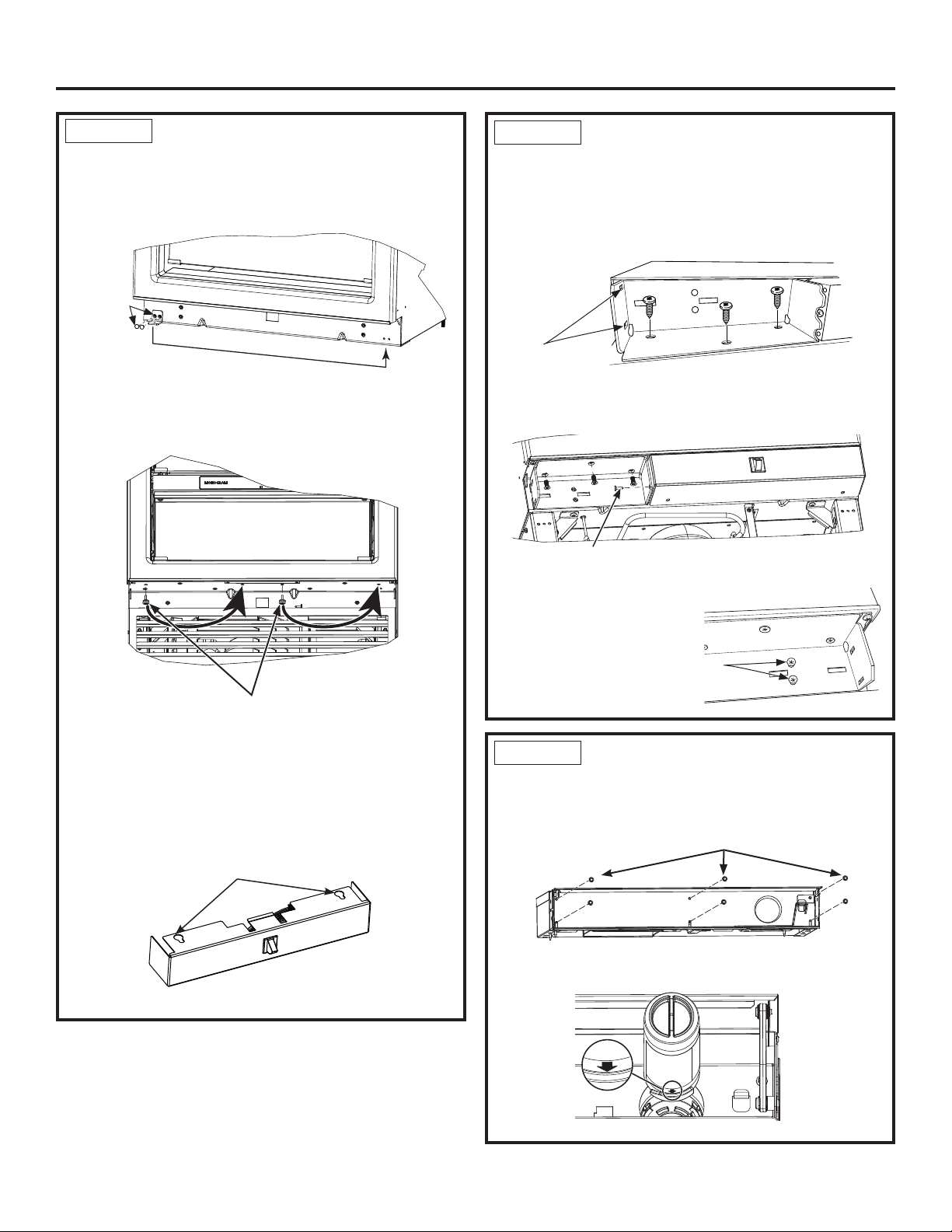
STEP 4 MOVE LIGHT SWITCH
HOUSING
Ŷ Remove front access cover from unit by removing
two 1/4” hex head screws.
Ŷ Lay the glass assembly on top of the control housing.
Ŷ Remove 4 screws, 2 on each end, to remove the
housing assembly using a 1/4” Hex bit.
Ŷ Move the housing assembly to the opposite side and
install using the 4 screws, 2 on each side.
NOTE: Make sure wires do not get pinched. On 18”
models, the red/white/black 5-pin wire connector
will need to be removed from the control board and
routed through the opposite corner bracket and
reconnected to the
control board to
prevent pinching
the wiring.
Wires must be rerouted from one
side to the other for 18” models.
5-pin wire connector
Access Cover
Ŷ Remove the Philip screw first and lower hinge
brackets by removing three T-30 Torx screws.
T-30 Torx Screws
Ŷ Remove screw with 1/4” hex bit driver at the bottom
corner of light switch housing.
Light Switch
Phillips Screw
1/4” Hex Head
Screws
Phillips Screw
8
31-1000190 Rev. 4
Page 9
Installation Instructions - Reversing the Door Swing
STEP 4 MOVE LIGHT SWITCH
HOUSING (Cont.)
Ŷ Move the mounting bracket to the other side of the
unit by removing two Philips screws and using them
to install the bracket in its new location.
Mounting
Bracket and
Screws
Ŷ Slide housing forward and down to remove from case
and grommets on case bottom.
Ŷ Keeping it connected to the unit, lay housing aside.
Grommets
STEP 5 REINSTALL HINGE
BRACKETS
Ŷ Move top hinge bracket to bottom and bottom bracket
to top.
Ŷ Ensure the 2 rectangular slots of bracket are on
outside, hinge side of case.
Rectangular
Slots
Ŷ Install both brackets with 3 T-30 Torx screws 45 in/lb
(5.1 Nm).
Phillips Screw
Ŷ Install the Phillips screw.
Ŷ Start 2 screws in
each bracket for
hinge mounting
but do not tighten
all the way.
Screws for
Hinge Brackets
Ŷ Remove 2 grommets with Phillips driver.
Ŷ Move grommets to the set of 2 holes on opposite
side.
Ŷ Align housing key holes over grommets and then
slide back until engaged. Ensure wires do not get
pinched.
Housing Key Holes
Ŷ Install Phillips screw into bottom hole to hold in place.
31-1000190 Rev. 4
STEP 6 REINSTALL THE
ENCLOSURE
Ŷ Install the enclosure assembly with removed six 1/4”
hex head screws.
Ŷ
Locate blue arrow on filter. Rotate filter to align arrow
as shown.
9
1/4” Hex Screws
Page 10
Installation Instructions - Reversing the Door Swing
STEP 6 REINSTALL THE
ENCLOSURE (Cont.)
Ŷ,QVHUW¿OWHULQWRSRVLWLRQDQGURWDWHóWXUQFORFNZLVH
XVH¿OWHUUHPRYDOWRROLIQHHGHG
Ŷ5HWXUQ¿OWHUUHPRYDOWRROWRPRXQWLQJKRRN
Ŷ
Close the compartment door.
STEP 7 REINSTALL THE FRONT
ACCESS COVER
Ŷ Put the access cover back onto the unit and secure
with two 1/4” hex head screws.
Access
Cover
STEP 8 REMOVE HINGES FROM
DOOR
WARNING
Point Hazard
Door hinges are under tension and should be left in
the open position throughout the reversal process.
Closing the hinge can lead to a finger pinch point
hazard.
Ŷ Remove 3 screws securing each hinge from the top
and bottom of the door and one screw securing the
support bracket to the door (T-30 Torx)
Ŷ Move the hinge assembly to the opposite end of the
door - top hinge to the bottom and bottom hinge to
the top. Hinge, L-bracket already attached to hinge,
and support bracket will all move together.
Ŷ 2 shims between the hinge bracket and door will
be moved to the other side -
save for installing the hinge.
Door Hinge Pinch
Support
Bracket
Shims
Hinge
1/4” Hex Screws
Ŷ Verify the two 1/4” hex head screws are assembled
to handle side of the products for both freezer and
fresh food columns.
1/4” Hex
Screws
10
31-1000190 Rev. 4
Page 11
Installation Instructions - Reversing the Door Swing
STEP 9 PANEL BRACKETS AND
HINGES
Ŷ Remove panel brackets on each end of the door by
removing the T30 Torx screws.
Ŷ Slide same bracket on each end to other side of door
and re-install brackets to door.
Ŷ Install hinges to door ensuring that 2 shims are
between hinge L-bracket and door. Install with 3 T-30
Torx screws 45 in/lb (5.1 Nm)
Shims
Hinge
Support
Bracket
NOTE: Ensure L-bracket remains attached to hinge
and is on the outer side of the door. Hinge is on the
inner door side.
REMINDER: Hinges have to move from top to bottom
and bottom to top.
Ŷ Install support bracket screw through both support
bracket and panel bracket.
STEP 10 REINSTALL THE DOOR
WARNING
the door swing. Failure to follow these instructions,
leaving off parts, or overtightening screws, can
lead to the door falling off and result in injury and
property damage.
Ŷ Ensure 2 hinge screws are started but not tightened
in hinge brackets on case.
Ŷ With 2nd person, hold door with hinges near correct
position.
Ŷ Install top hinges with key hole over screws and slide
bracket.
Ŷ Repeat on bottom.
NOTE: Ensure 2 tabs on hinges are inserted into
the rectangular slots on outside of hinge brackets
BEFORE tightening screws.
Follow all steps when reversing
Key hole slot
over screws
31-1000190 Rev. 4
Tabs in
rectangular slots
Ŷ Tighten bottom screws 45 in/lb (5.1 Nm).
Ŷ Tighten top screws 45 in/lb (5.1 Nm).
Ŷ Carefully ensure door closes correctly and gasket
aligns with case.
11
Page 12

Instructions for Dual Integrated Installation
New construction installation with 25” deep openings
12
31-1000190 Rev. 4
Page 13
Design Guide - Dual Integrated Installation
DUAL INTEGRATED INSTALLATION SPACE
Dimensions in parentheses are in centimeters.
18” Integrated Freezer
24” Integrated Refrigerator
41 1/2" (105.4)
3 1/2"
(8.9)
Finished
Return
25" (63.5)
24” Integrated Freezer
24” Integrated Refrigerator
47 1/2"
(120.7)
3 1/2"
(8.9)
Finished
Return
25" (63.5)
84"
(213.4)
27 1/4"
(69.2)
4"
(10.2)
22 1/8" (56.2)
7 1/2”
(19.1)
2"
4 1/8"
(10.5)
3 1/2"
(8.9)
(15.24)
6"
(5.1)
5"
(12.7)
6"
(15.24)
2 1/2"
(6.4)
4"
E
W
(10.2)
2 1/2"
(6.4)
FRONT VIEW
ELEC W
18” Integrated Freezer
30” Integrated Refrigerator
47 1/2"
(120.7)
(213.4)
4 1/8"
(10.5)
84"
(15.24)
6"
3 1/2"
(8.9)
22 1/8" (56.2)
7 1/2"
(19.1)
E
28" (71.1)
W
2"
(5.1)
2 1/2"
4"
(10.2)
(6.4)
6 1/4"
(10.2)
ELEC W
5"
(12.7)
FRONT VIEW
6"
(15.24)
2 1/2"
(6.4)
30” Integrated Freezer
30” Integrated Refrigerator
3 1/2"
(8.9)
Finished
Return
SIDE VIEW
25" (63.5)
SIDE VIEW
Back
84"
Back
(213.4)
4 3/8"
(11.1)
9 1/2"
(24.1)
ELEC W
33 1/4" (84.5)
28 1/8" (71.4)
4
2 1/2"
5"
(12.7)
6"
ELEC W
(15.24)
(6.4)
FRONT VIEW
24” Integrated Freezer
30” Integrated Refrigerator
53 1/2" (134.6)
84"
84"
(213.4)
4 3/8"
(11.1)
9 1/2"
(24.1)
ELEC W
34" (86.4)
28 1/8" (71.4)
4"
(10.2)
5"
(12.7)
6"
(15.24)
2 1/2"
(6.4)
FRONT VIEW
6 1/4"
(15.9)
ELEC W
(12.7)
5"
(10.2)
5"
(12.7)
4"
6"
(15.24)
2 1/2"
(6.4)
3 1/2"
Finished
Return
(8.9)
SIDE VIEW
25
25" (63.5)
Back
Back
6"
(15.24)
2 1/2"
(6.4)
SIDE VIEW
84"
84"
(213.4)
9 1/2"
(10.2)
(24.1)
4 3/8"
(11.1)
ELEC W
(12.7)
31-1000190 Rev. 4
40" (101.6)
34 1/8" (86.67)
4"
6"
(15.24)
2 1/2"
5"
(6.4)
FRONT VIEW
59 1/2" (151.3)
6 1/4"
(15.9)
ELEC W
(12.7)
25
3 1/2"
(8.9)
Finished
Return
25" (63.5)
Back
6"
(15.24)
2 1/2"
5"
(6.4)
SIDE VIEW
13
Page 14
Design Guide - Dual Integrated Installation
DUAL INTEGRATED INSTALLATION SPACE
Water And Electrical Locations
Electrical and water supply must be located as shown.
The Cutout Depth Must Be 25”
Cutout is based on installation of 2 products with a leftand-right hand door swing.
Heater Unification Kit ZKUN required.
Product Clearances
These units are equipped with a 2-position door stop.
The factory set 115° door swing can be adjusted to 90°
if clearance to adjacent cabinets or walls is restricted.
For a 90° door swing, allow 4” (10.2 cm) minimum
clearance to a wall.
When installed in a corner, allow 15” (38.1 cm) for a full
115° door swing on 18” and 24” models. Allow 16.5”
(41.9 cm) on 30” models.
Additional Specifications
• A separate 115 volt 60Hz., 15 or 20 amp power supply
is recommended for each product. An individual
properly grounded branch circuit or circuit breaker is
recommended. Install a properly grounded 3-prong
electrical receptacle recessed into the back wall.
Electrical must be located on rear wall as shown.
• Water line must be located on the back wall as shown.
The water line should be 1/4” O.D. copper tubing or
QuickConnect
water line and water connection location, long enough
to extend to the front of the unit (8’ [2.4m]). Installation
of an easily accessible shut-off valve in the water line
is required.
• A minimum of 3-1/2” finished return matching cabinet
exterior is recommended on interior on all sides and
top at front of opening.
™
kit (WX08X10006) between the cold
REFRIGERATOR/FREEZER LOCATION
Ŷ Do not install the refrigerator/freezer where the tem-
perature will go below 55°F (13°C). It will not run
often enough to maintain proper temperatures.
Ŷ Do not install the refrigerator/freezer where
temperatures will go above 100°F (37°C). It will not
perform properly.
Ŷ Do not install the refrigerator/freezer in a location
exposed to water (rain, etc.) or direct sunlight.
Ŷ Install it on a floor strong enough to support it fully
loaded.
HARDWARE SUPPLIED (per unit)
• Water Filter Bypass Plug (if equipped)
• Air filter (if equipped)
• Anti-Tip bracket
• 3 Lag screws
• 3 Tapcon screws
• 3 Toggles with bolts
• Panel installation templates
• 2 Door trims
• 2 Door panel brackets
• Set screws
• #6 Phillips head wood screws
• Door Bracket Cover Top
• T30 screws
• 1 Hinge limiter pin
• Center door panel bracket
• Hi-Lo screw and square washer
• Stainless Toe Kick
• Painted access cover screws
• T10 screw
TOOLS AND MATERIALS REQUIRED
• Metal shears
• #1, #2 Phillips screwdriver
• Flathead screwdriver
• Putty knife
• Measuring tape
• Drill and 1/16”, 5/64”, 3/16”, 1/2” bits
• 5/32” concrete bit (if installing anti-tip into concrete)
• 1/4”, 3/8”, 7/16” driver/socket
• 7/16” open wrench
• T10, T20, T30 driver/bit
• 1/8”, 1/4” hex driver (allen wrench)
• Level
• Water shut-off valves (optional but recommended)
• 8’ waterline (one per unit requiring water hookup)
• Masking tape
• Rubbing alcohol
• Adjustable wrench
• Center punch
• Heater Unification Kit (ZKUN)
• Stainless Steel Door Kits (if applicable)
• Custom panels for doors (if applicable)
• Handle Kits (if applicable)
• Small Ratchet
14
31-1000190 Rev. 4
Page 15
Installation Instructions - Dual Integrated Installation
KIT ZKUN PARTS SUPPLIED:
Adhesive Heater
Transformer
Front Mullion
Trim Bracket
Top Unification Bracket
Bottom Front Unification Bracket
3 1/4” Hex Head 8-18 5/8” Long Screws
5 1/4” Hex Head 8-32 5/8” Long Screws
5 3/8” Hex Head 1/4-20 1/2” Long Screws
4 wire clips
Tools and Materials Required:
1/4” and 3/8” driver / sockets
#2 Phillips screwdriver
Rubbing alcohol
GROUNDING THE UNIT
WARNING
Hazard. Failure to follow these instructions can
result in death, fire, or electrical shock.
The power cord of this appliance is equipped with a
3-prong (grounding) plug which mates with a standard
3-prong (grounding) wall receptacle to minimize the
possibility of electric shock hazard from this appliance.
Have the wall outlet and circuit checked by a qualified
electrician to make sure the outlet is properly grounded.
Where a standard 2-prong wall outlet is encountered, it
is your personal responsibility and obligation to have it
replaced with a properly grounded 3-prong wall outlet.
DO NOT, UNDER ANY CIRCUMSTANCES, CUT OR
REMOVE THE THIRD (GROUND) PRONG
FROM THE POWER CORD.
DO NOT USE AN ADAPTER PLUG TO
CONNECT THE REFRIGERATOR TO A
2-PRONG OUTLET.
DO NOT USE AN EXTENSION CORD
WITH THIS APPLIANCE.
Electrical Shock
FLOORING
For proper installation, this product must be placed
on a level surface of hard material that is at the same
height as the rest of the flooring. This surface should
be strong enough to support a fully loaded refrigerator
or freezer, or approximately 1,200 lbs. per unit.
NOTE: Protect the finish of the flooring.
NOTE: Not recommended for installation on carpeted
flooring.
31-1000190 Rev. 4
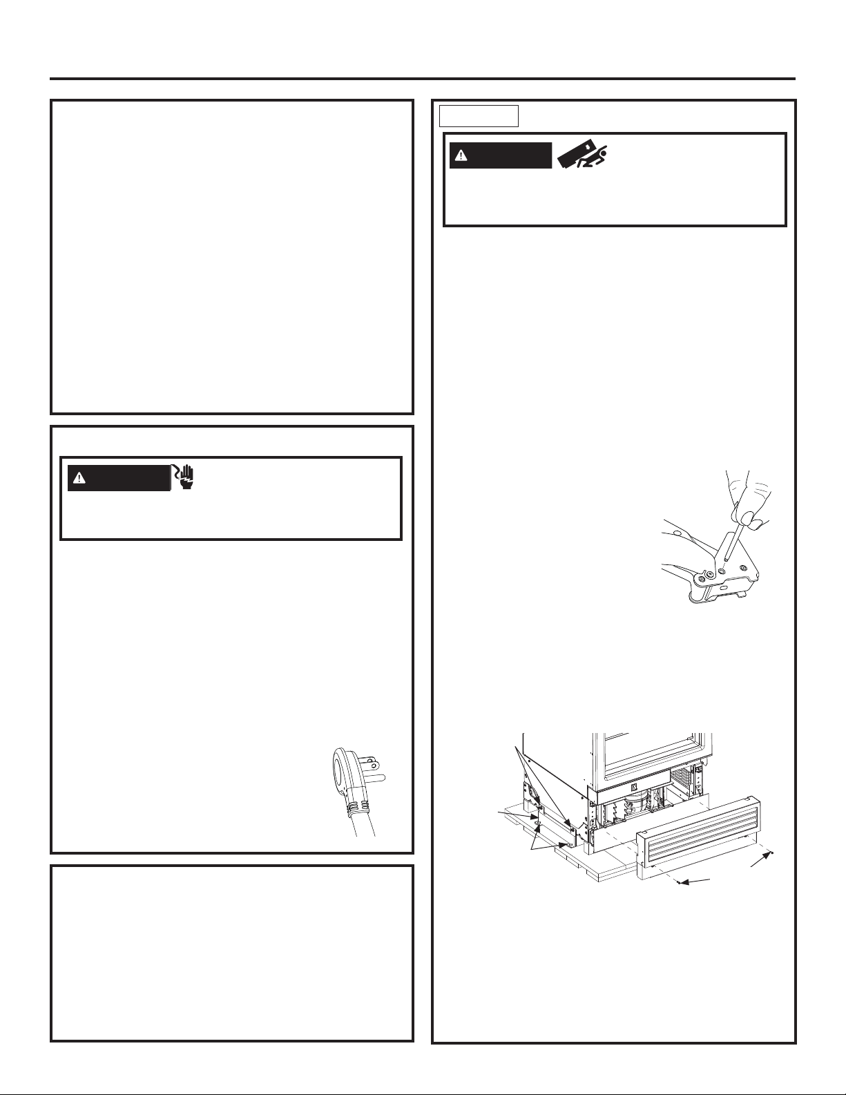
STEP 1 REMOVE PACKAGING
WARNING
appliance is top heavy. Use extreme caution with
moving to prevent tipping over which could result in
death or serious injury.
Ŷ Remove outer carton and external packing from units.
Ŷ Inspect for damage.
Ŷ If installation will require the door swing to be
reversed, follow the instructions in Reversing the
Door Swing section to reverse the door swing
BEFORE the unit is removed from the shipping skid.
Ŷ Ensure the flooring that the units are set is clean/
free of debris that could be collected on to, or
pinched in front of the wheels and damaging the
floor. Additionally, it is recommended that the floor
be protected with a plastic covering through out the
installation process.
Ŷ Remove hardware kit from top drawer.
Ŷ If installation requires a 90° door opening, the hinge
limiter pin must be installed in the
top hinge BEFORE the unit is
removed from the shipping skid.
Pin is located in the hardware kit.
- Open the door approximately
45°, but no wider than 90°, to
expose the hole in the back
hinge bracket and install the
limiting pin. Pin must be fully
seated in the bracket or the door will not close
properly.
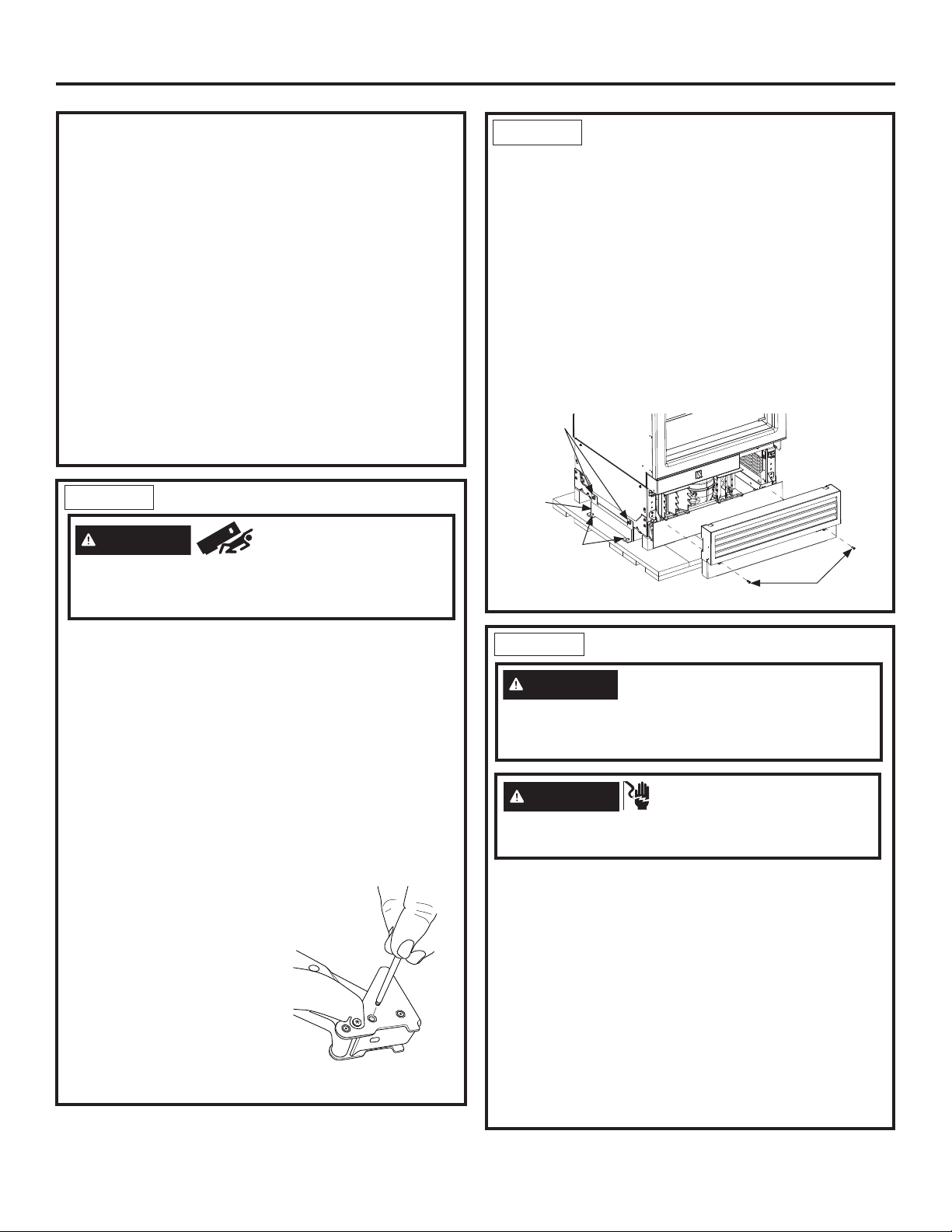
Ŷ Remove front access cover from unit by removing
two 1/4” hex head screws. (Some models have
access cover in a box on the left side of the cabinet.)
Place the cover and screws to the side for future
installation.
3/8” Drive
Screws
Shipping
Bracket
7/16” Drive
Screws
Ŷ Remove three 3/8” drive screws and two 7/16” drive
screws from each side of the unit to release it from
the shipping skid. Tip the unit from the side enough
to remove the shipping material from under the unit,
but above the shipping skid (both sides)
Ŷ CAREFULLY roll the unit off the back side of the
shipping skid.
Ŷ Handle from side only with a hand truck.
15
Tip Over Hazard. This
1/4” Hex Head
Screws
Top
Hinge
Page 16
Installation Instructions - Dual Integrated Installation
STEP 2 INSTALL WATER LINE
WARNING
only. A cold water supply is required for automatic
icemaker operation. The water pressure must be
between 40 and 120 psi (275-827 kilopascals).
WARNING
Attach tubing clamp using existing hole only. DO
NOT drill into the refrigerator.
Shut off the main water supply.
Turn on the nearest faucet long enough to clear the
line of water.
ŶInstall a shut-off valve between the water valve and
cold water pipe in a basement or cabinet. The shutoff valve should be located where it will be easily
accessible.
ŶTurn on the main water supply and flush debris.
Run about a quart of water through the tubing into a
bucket. Shut off water supply at the shut-off valve.
NOTE: Saddle type shut-off valves are included in
many water supply kits. Before purchasing, make sure
a saddle type valve complies with your local plumbing
codes.
NOTE: Commonwealth of Massachusetts Plumbing
Codes 248CMR shall be adhered to. Saddle
valves are illegal and use is not permitted in
Massachusetts. Consult with your licensed plumber.
Connect to potable water supply
ELECTRIC SHOCK HAZARD
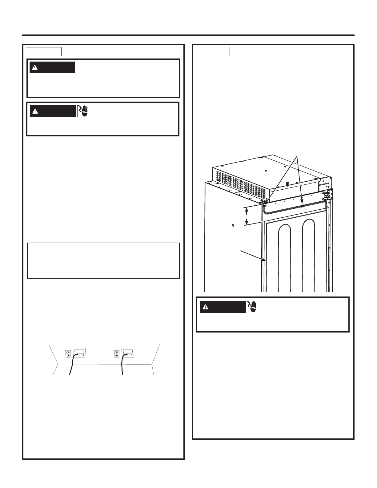
STEP 3 PREPARING UNIT FOR
INSTALLATION
Ŷ Unpack the heater Unification Kit (ZKUN) and make
sure all of the components on the list are included.
NOTE: Ensure the heater connector cord is toward the
top of the unit when installed.
Ŷ Place the right hand unit in front of the installation
opening in a way that the unit is in front of the
intended installed location.
Ŷ Install adhesive heater on the outside of the unit to
the left side of the case. Install heater 4” below the
case top. Heater should be centered front to back on
the metal case.
4”
Adhesive
Heater
Clips
Ŷ Route 1/4” OD copper or SmartConnect™
(WX08X10006) plastic tubing between house cold
water line and the water connection location at the
front of the unit.
SmartConnect™ Refrigerator Tubing Kits are
available. One 8’ (2.4m) water line (WX08X10006) is
needed for each unit. The waterline(s) will be taped
to the floor using masking tape after anti-tip bracket
installation.
Ŷ Tubing should be long enough to extend to the front
of the unit. Allow enough tubing to accommodate
bend leading into the water line connection. Unit
must be tipped on its side to route waterline
underneath and to the front of the appliance.
NOTE: The only GE Appliances approved plastic
tubing is supplied in the SmartConnect™ Refrigerator
Tubing kits. Do not use any other plastic water supply
line because the line is under pressure at all times.
Other types of plastic may crack or rupture with age
and cause water damage to your home.
WARNING
Electrical Shock
Hazard. To avoid the risk of electric shock, make
sure the power cord is not plugged into the wall outlet.
Ŷ Install the transformer into the case top assembly:
1. Remove cover top by removing eight #8 hex screws
and keep aside for assembling back the cover top.
2. Place the transformer into the case top provided in
ZKUN kit and secure it with the existing (1/4”) hex
screws to left front of case top.
3. Connect the 2 pin transformer connector to the
heater connector and 3 pin connector to panel
control, make sure locking tabs are engaged.
4. NOTE: Verify the master switch is on.
5. Assemble the cover top with screws save from
previous step.
16
31-1000190 Rev. 4
Page 17
Installation Instructions - Dual Integrated Installation
STEP 3 PREPARING UNIT FOR
INSTALLATION (Cont.)
#8 Hex
Screws
2 Pin
Connector
to Heater
Connector
Do NOT
Remove Wire
Standoff
Transformer
3 Pin
Connector
Master Switch
Enclosure assembly upper
is hidden for clarity.
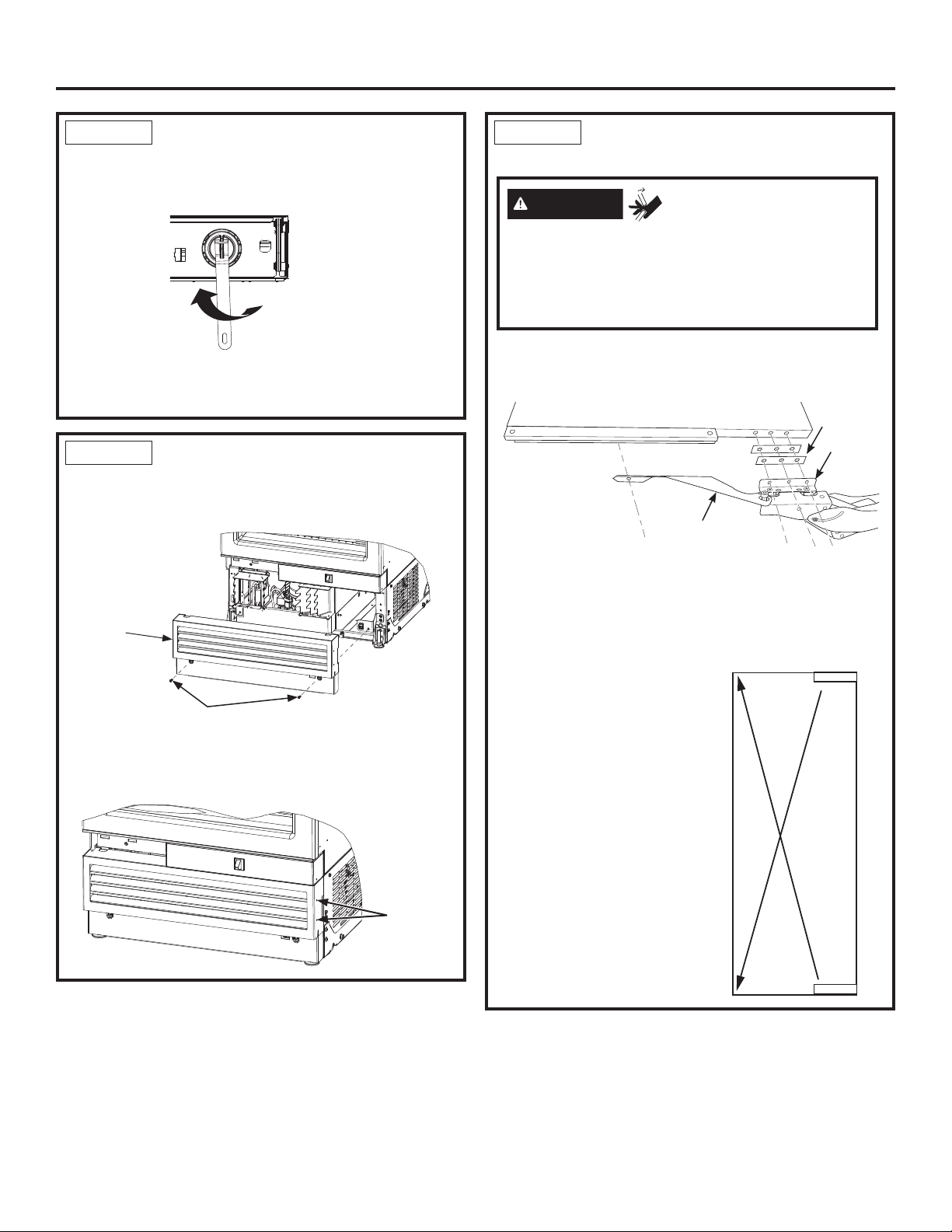
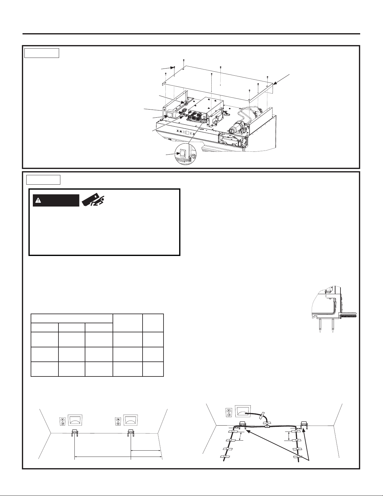
STEP 4
WARNING
INSTALL ANTI-TIP BRACKET
Tip Over Hazard.
These appliances are top heavy, especially with any
doors open, and must be secured to prevent tipping
forward which could result in death or serious injury.
Read and follow the entire installation instructions
for securing the appliance with the anti-tip system.
Ŷ Remove the anti-tip bracket from the hardware kit.
Ŷ Anti-tip bracket should be mounted against the back
wall or up to 25-1/2” (64.7 cm) maximum from front of
opening. Use floor mounting method if the bracket is
not against a wall (bracket hardware is provided for
mounting into wood, steel studs and concrete).
LH Unit
18” 24” 30”
26-5/8”
67.6 cm
32-5/8”
82.8 cm
38-5/8”
98.1 cm
23-1/2”
59.7 cm
29-1/2”
74.9 cm
35-1/2”
90.1 cm
23-1/2”
59.7 cm
29-1/2”
74.9 cm
35-1/2”
90.1 cm
RH UNIT
8-7/8”
22.5 CM
5-3/4”
14.5 CM
5-3/4”
14.5 CM
Cover Top
18”
24”
30”
STEP 4
INSTALL ANTI-TIP BRACKET
(Cont.)
Ŷ Measure and mark from the RH side of the opening
per the table above depending on the size of the RH
unit you are installing.
RH Unit
LH Unit
Ŷ Measure and mark again from the RH side of
the opening per the table and depending on your
combination of LH and RH units.
For example, if installing an 18” LH unit and a 30” RH
unit, use 5-3/4” and 38-5/8”.
Ŷ Mount the anti-tip bracket centered about the marks
and flush to the floor as shown. Mark 3 holes for wall
mounting or 4 holes for floor mounting.
WOOD MOUNTING: Predrill with 3/16” drill bit, 2”
deep, then install lag bolts with a 7/16” driver.
CONCRETE MOUNTING: Predrill with a 5/32”
concrete bit, 2” deep, then install
tapcon screws with a 7/16” driver.
STEEL MOUNTING: Predrill with a
1/2” drill bit, insert toggle, then install
bolts with a 7/16” driver.
The bracket must be screwed to
either the FLOOR or REAR WALL.
Ŷ If the enclosure is deeper than 25 ½”, the anti-tip
bracket should be secured to the floor 25” from front
of the enclosure.
Ŷ Tape the waterline to the wall and floor approximately
3” to the left of the anti-tip bracket. Apply tape about
every 5” toward the front of the opening (tape will
prevent the unit from rolling over the waterline during
installation). Do not tape near the cabinet front in
order to keep tape hidden under the unit.
3"
5"
3"
5"
31-1000190 Rev. 4
17
Page 18
Installation Instructions - Dual Integrated Installation
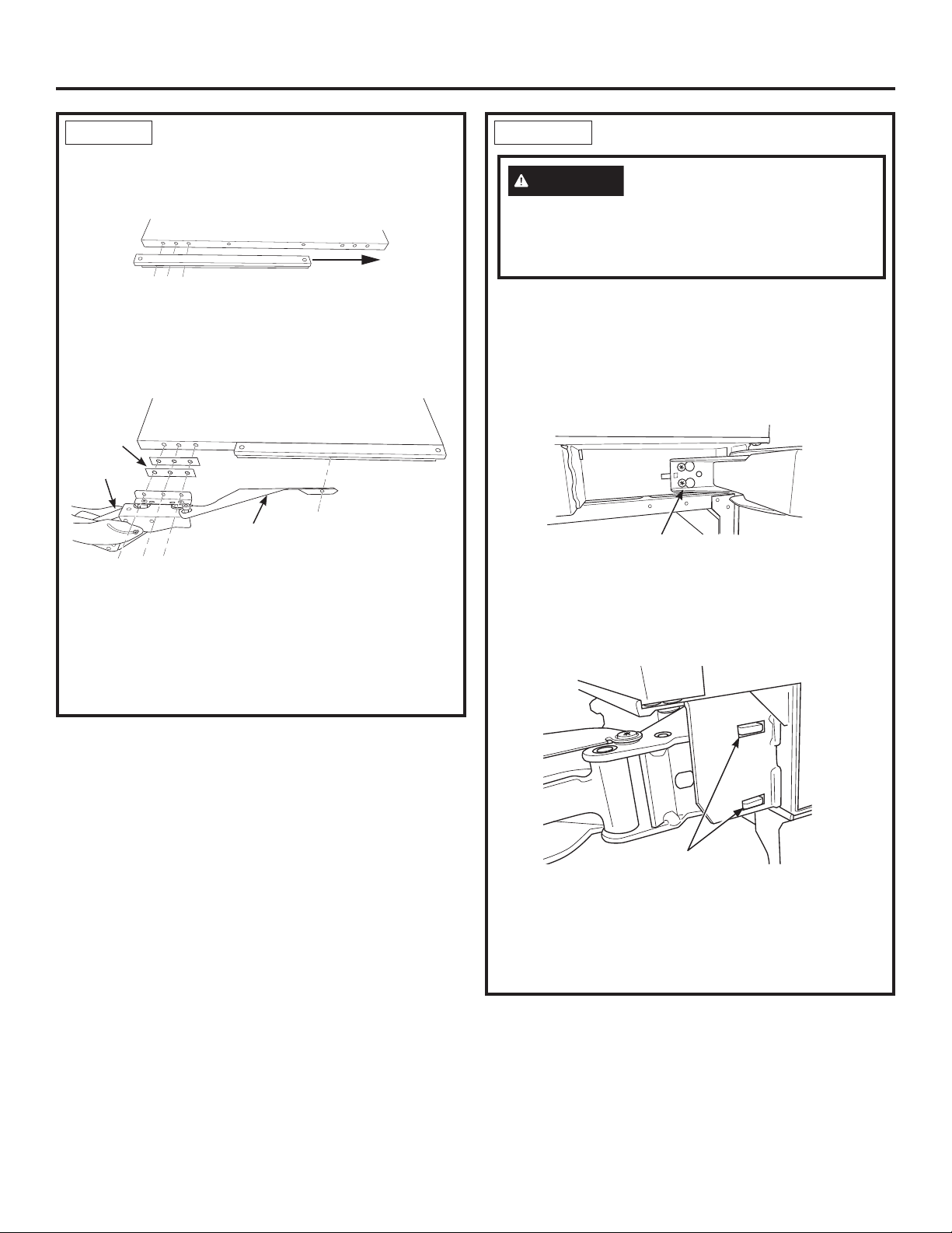
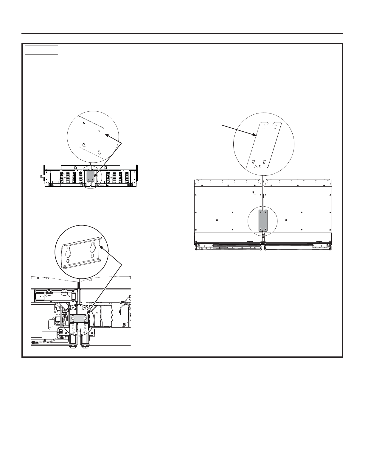
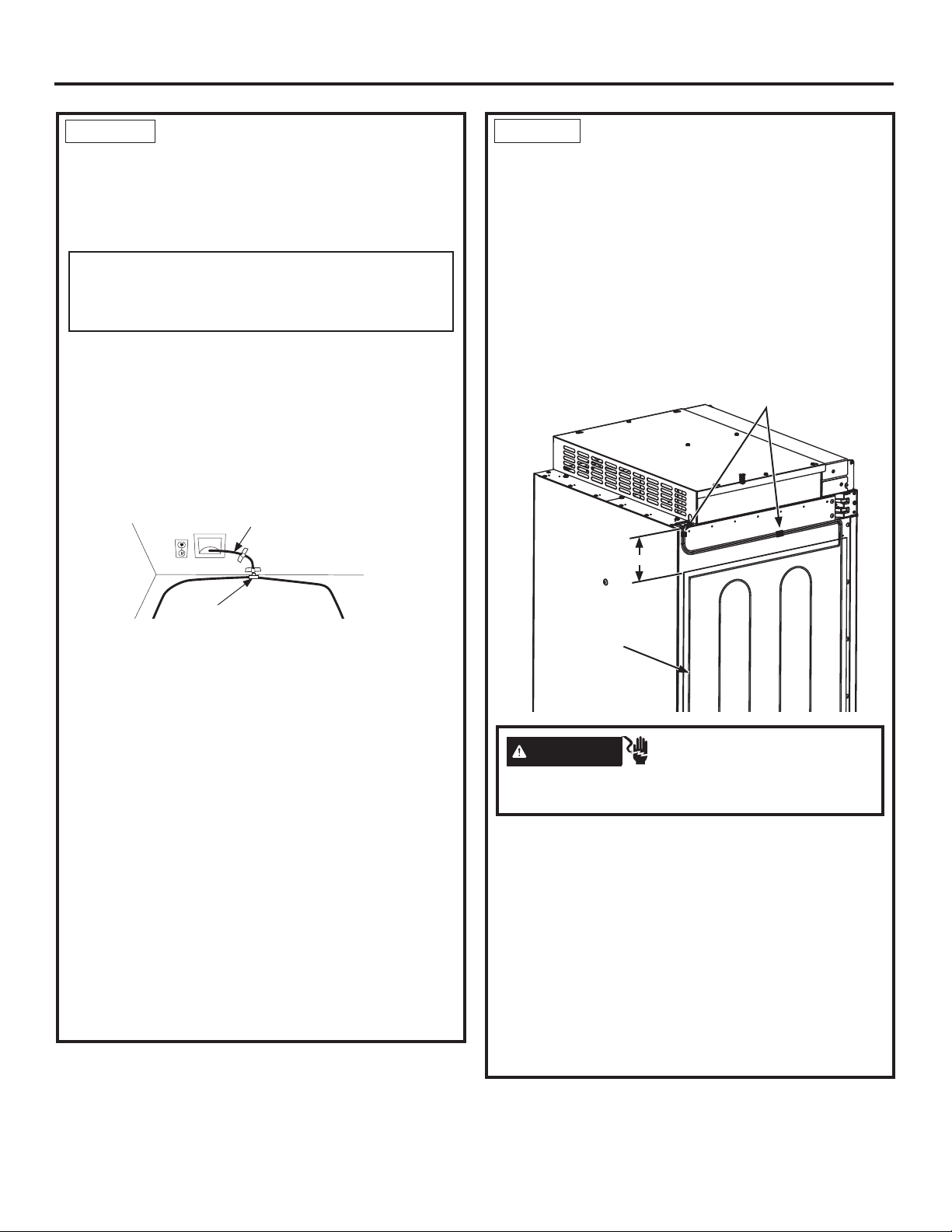
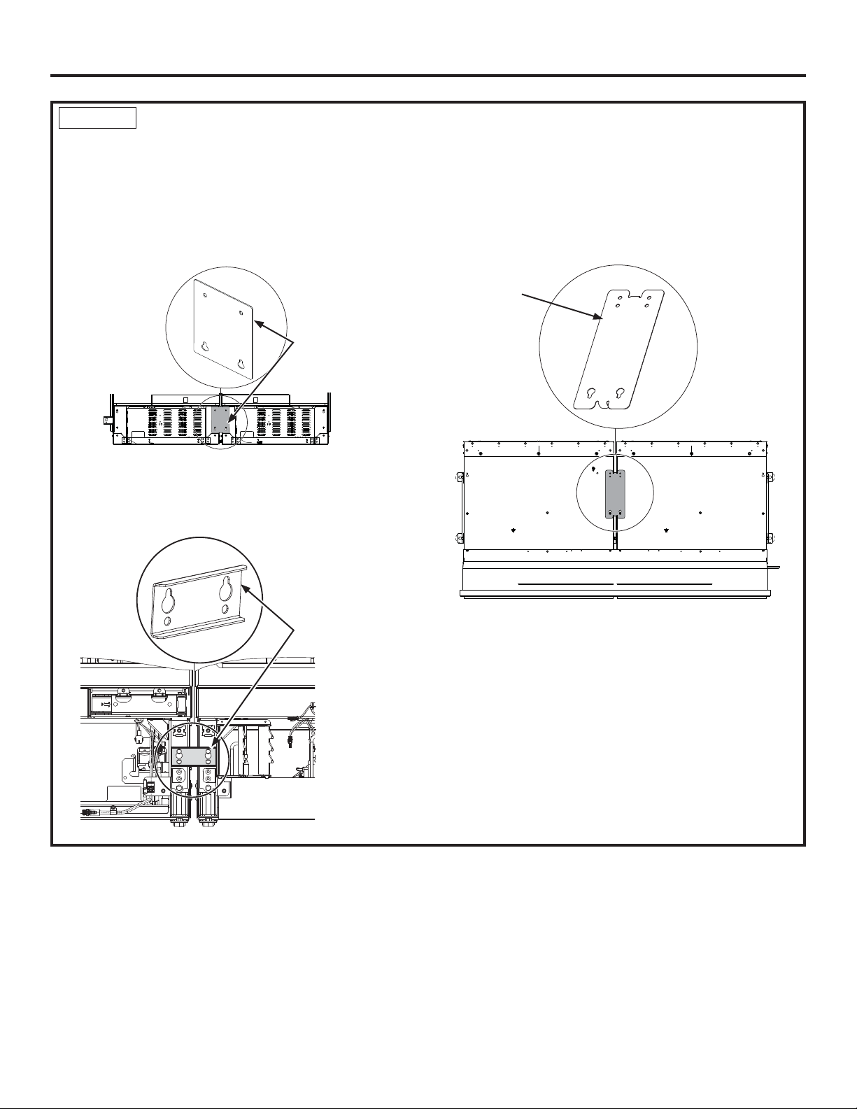
STEP 5
BOTTOM BACK UNIFICATION
Ŷ Loosen the two bottom screws of rear access covers of
both units and remove the top screws.
Ŷ Hang the unification bracket to the bottom screws and
reassemble the screws at the top
Ŷ Tighten screws to tie units together.
BOTTOM FRONT UNIFICATION
Ŷ Install the bottom front unification bracket using a 3/8”
driver (4 screws).
JOINING DUAL INSTALLED UNITS
8QL¿FDWLRQ
Bracket
TOP UNIFICATION
Ŷ Loosen the front two screws on top of the unit and
remove the two middle screws.
Ŷ Assemble the bracket to the front screws and reinstall
the middle screws.
Ŷ Tighten screws to tie units together.
8QL¿FDWLRQ
Bracket
8QL¿FDWLRQ%UDFNHW
Front of appliances
18
31-1000190 Rev. 4
Page 19
Installation Instructions - Dual Integrated Installation
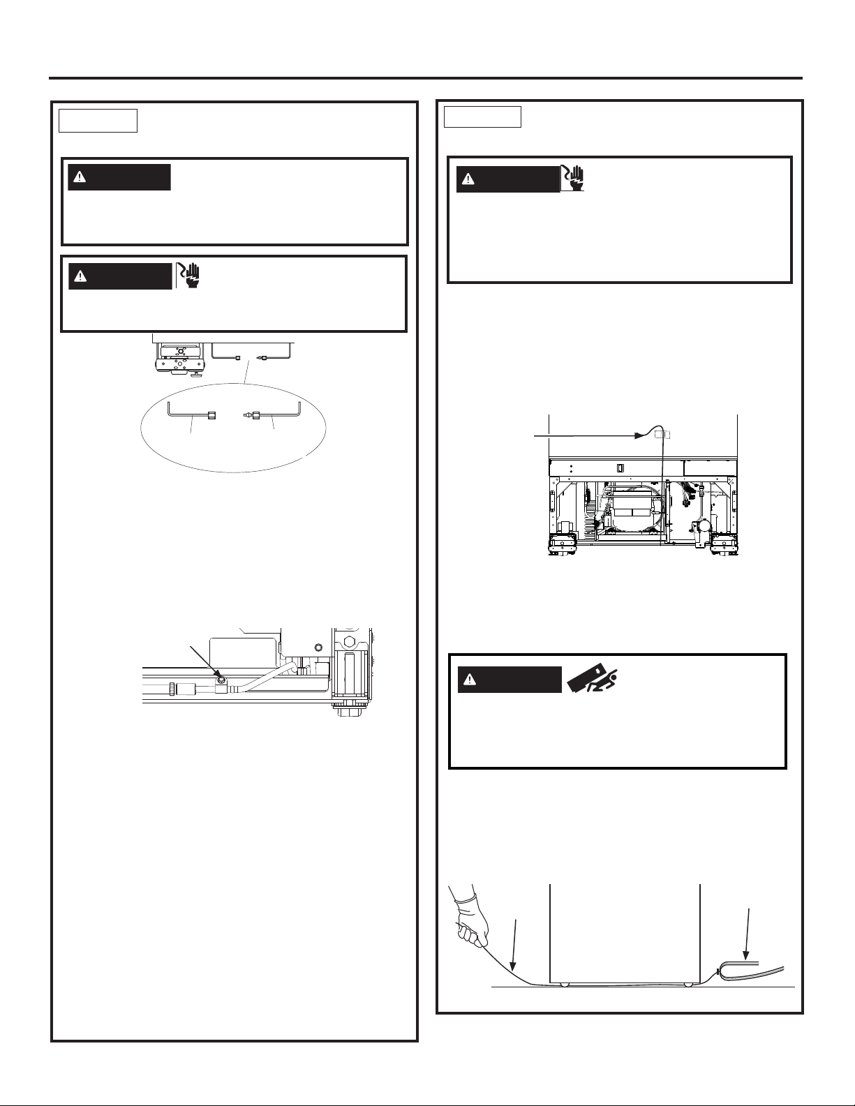
STEP 6
CONNECTING WATER
SUPPLY
WARNING
only. A cold water supply is required for automatic
icemaker operation. The water pressure must be
between 40 and 120 psi (275-827 kilopascals).
WARNING
Attach tubing clamp using existing hole only. DO
NOT drill into the refrigerator.
Ŷ Locate and bring the tubing to the front of the
cabinet.
Ŷ Turn the water on to flush debris from the line. Run
about a quart of water through the tubing into a
bucket, then shut off the water.
Ŷ Remove strain relief screw to allow for enough slack
to make a proper water connection. (Screw must be
replaced in the next step.)
Strain Relief
Screw
Connect to potable water supply
ELECTRIC SHOCK HAZARD
House
Water Supply
Refrigerator/
Freezer
Freezer
Water Supply
Water Supply
STEP 7 INSERTING/SECURING
INTO CABINET SURROUND
WARNING
To reduce the risk of electrical shock, be careful
during the remaining installation steps not to touch
wiring or electrical components inside the compressor
compartment while the appliance is plugged in and
the front access cover is not in place.
Ŷ Plug both units into the outlet in the wall.
Ŷ Find the installation string that is attached to the door
of the unit; this is to be used as you are pushing the
unit back into the opening. The string is attached to
the power cord; as you walk the unit back into the
opening you should pull the string tight to make sure
the power cord is routed underneath the unit.
Installation
String
Ŷ Slowly walk both units into opening making sure not
to touch the cabinetry on the sides and top to prevent
damage. Both door faces should be 7/8” behind
the front face of surrounding cabinets on either a
stainless or custom panel installation.
Electrical Shock Hazard.
Copper Tubing:
Ŷ Slip a 1/4” nut and ferrule (provided) over both ends
of the copper tubing. Insert the tube into the union
fitting on the unit and tighten the nut to the union.
Ŷ Turn on the water to check for leaks.
SmartConnect™ Tubing:
NOTE: The only GE Appliances-approved plastic
tubing is supplied in the SmartConnect™ Refrigerator
Tubing kits. Do not use any other plastic water supply
line because the line is under pressure at all times.
Other types of plastic may crack or rupture with age
and cause water damage to your home.
Ŷ Insert the molded end of the tubing into the
refrigerator or freezer connection. Tighten the
compression nut until it is just hand-tight.
Ŷ Follow the instructions provided with the tubing.
Overtightening can cause leaks!
Ŷ Turn on the water to check for leaks.
31-1000190 Rev. 4
WARNING
These appliances are top heavy, especially with
any doors open, and must be secured to prevent
tipping forward which could result in death or
serious injury.
Ŷ Place power cord on its edge and pull under product
between rollers and away from the anti-tip bracket to
ensure cord is not damaged during installation.
Ŷ As you walk the unit back into the opening, you
should pull the string tight to make sure the power
cord is routed underneath the unit.
String
Tip Over Hazard.
Power Cord
19
Page 20
Installation Instructions - Dual Integrated Installation
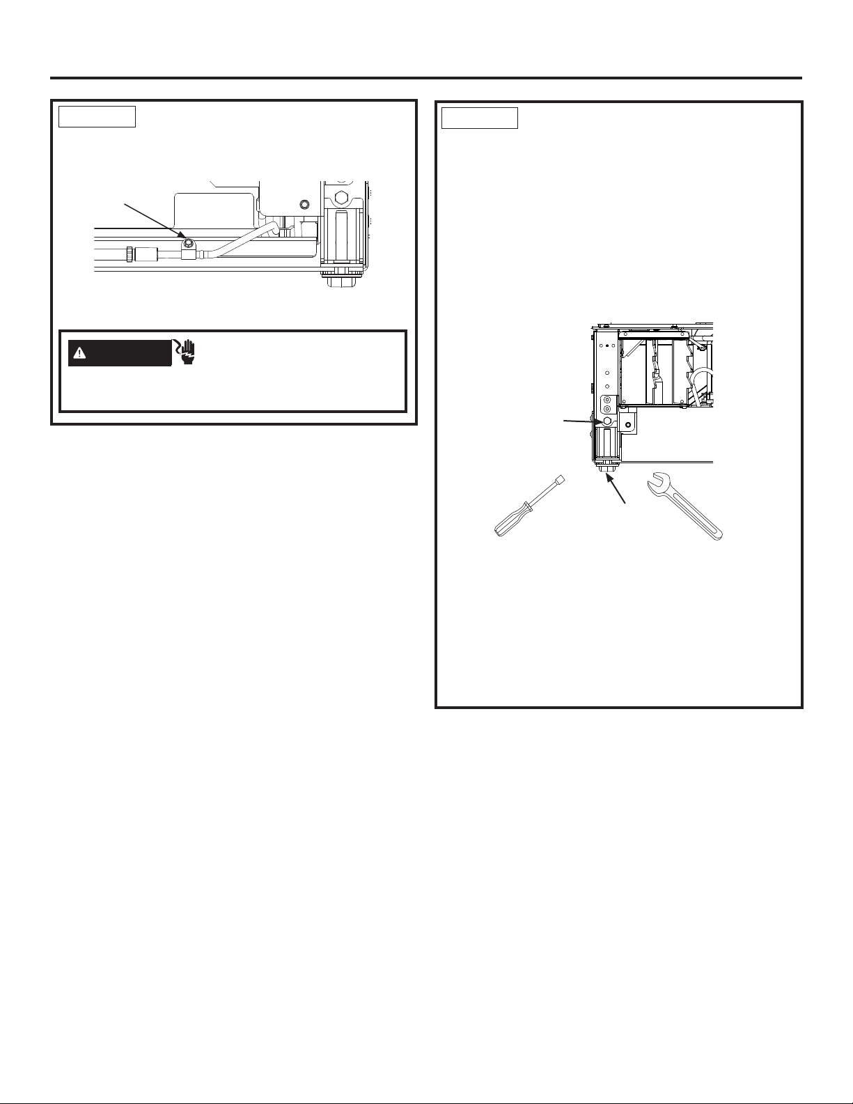
STEP 7 INSERTING/SECURING
INTO CABINET SURROUND (Cont.)
Ŷ Replace the waterline strain relief screw.
Strain Relief
Screw
Ŷ Store the excess string, and water tubing under
the unit.
WARNING
Replace waterline strain relief in front rail location as
shown.
Electrical Shock Hazard.
STEP 8 LEVEL UNIT
All models have 4-point leveling. The front is supported
by leveling legs; the rear is supported by adjustable
wheels. Both are accessible from the front of the unit.
Ŷ To level the back of the unit, turn the 7/16” hex nut
located above the front wheels. Turn clockwise to
raise or counterclockwise to lower the unit.
Ŷ For front leveling, use a 7/16” open-end wrench.
Ŷ Adjust height of unit to match installation cutout
opening 84”. The unit should be level and plumb with
cabinetry.
Hex nut adjusts
rear wheels
Open-end wrench
adjusts front
leveling legs
NOTICE: The rear leveling wheels and front leveling
legs are limited to a maximum height adjustment of 1”.
If the installation requires more than 84” height, the
installer should elevate the unit on a sheet of plywood
or runners. Cabinetry trim could also be added across
the top of the opening to shorten the opening. If you
attempt to raise the unit more than 1”, you will damage
the front leveling legs and the rear leveling wheels.
20
31-1000190 Rev. 4
Page 21
Installation Instructions - Dual Integrated Installation
STEP 9
FINAL EXTERNAL UNIT
PREPARATION
FOR FLUSH INSTALLATION: Make sure front surface
of the door is 7/8” behind front face of surrounding
cabinets BEFORE securing brackets to the surrounding
cabinetry.
Ŷ Open the doors to
the units. Locate
¿OWHUDQG¿OWHU
removal tool. Filter
should be as shown.
Ŷ5RWDWH¿OWHUóWXUQ
counterclockwise
XVH¿OWHUUHPRYDO
tool if needed).
Ŷ3XOO¿OWHUWRZDUG\RXWR
remove. NOTE: Water
system will not function
ZLWKRXW¿OWHULQSODFH
Ŷ Make sure lights are on inside the unit. If they are not
on, check to make sure the master switch is on by
removing the front enclosure which is secured with
six 1/4” Hex screws.
1/4” Hex Screws
Compartment Door
Filter
Mounting
Hook
Filter Removal Tool
STEP 9 FINAL EXTERNAL UNIT
PREPARATION (Cont.)
1/4” Hex Screws
Ŷ Locate blue arrow on
¿OWHU5RWDWH¿OWHUWR
align arrow as shown.
Ŷ,QVHUW¿OWHULQWRSRVLWLRQ
DQGURWDWHóWXUQ
FORFNZLVHXVH¿OWHU
removal tool if needed).
Ŷ5HWXUQ¿OWHUUHPRYDOWRROWR
mounting hook.
Ŷ
Close the compartment door.
Ŷ Verify the two 1/4” hex head
screws are assembled to handle
side of the products for both
freezer and fresh food columns.
Ŷ Switch on the master switch if not on. (Master Switch
Wires hidden for clarity.
Master Switch
Ŷ Assemble the enclosure with removed screws.
Ŷ Predrill 1/16” holes is both the sides of the surround
1/2” deep through holes in the enclosure.
Ŷ Secure unit by driving four 1/4” hex screws to both
sides to surrounding cabinetry. NOTE: This step
does NOT replace the anti-tip safety hardware. Refer
to Step 4 Installing Anti-Tip Bracket and Step 7
Inserting/Securing into Cabinet Surround for details
on installing the anti-tip hardware. Repeat for the
second unit.
1/4” Hex Screws
Ŷ Put the access cover back onto the unit and secure
with two 1/4” hex head screws.
Access
Cover
1/4” Hex
Screws
31-1000190 Rev. 4
21
Page 22
Installation Instructions - Dual Integrated Installation
STEP 9
FINAL EXTERNAL UNIT
PREPARATION (Cont.)
Ŷ Install front mullion and access cover trims between
the 2 units. Open the doors and the flexible dart in
the area between units.
Ŷ Top dart of the mullion must align with bottom edge
of the case trim.
Mullion Trim
“Dart”
Ŷ Open both enclosure doors to 90°.
Ŷ Snap the trim bracket between the water filter access
enclosures above displays.
Trim
Top Dart
STEP 11 INTERNAL UNIT
PREPARATION
Ŷ Remove all tape, cardboard, and foam from each unit
(foam shipping supports may be located behind the
left and right sides of each of the glass pan fronts on
Refrigerator models).
Ŷ Remove boxed door bins from shelves.
Ŷ Unbox and install door bins.
Ŷ Install door bin mats.
STEP 12 START ICEMAKER
(freezer models)
CAUTION
injury, avoid contact with the moving parts of the
ejector mechanism, or with the heating element that
releases the cubes. Do not place fingers or hands on
the automatic ice making mechanism while the
appliance is plugged in.
A newly-installed freezer may take 12–24 hours to
begin making ice.
The icemaker will produce seven cubes per cycle—
approximately 15 cycles in a 24-hour period,
depending on freezer compartment temperature, room
temperature, number of door openings and other use
conditions.
If the freezer is operated before the water connection
is made to the icemaker, set the power switch to
OFF. Top wire basket must be removed to access the
icemaker power switch.
When the freezer has been connected to the water
supply, set the power switch to ON.
Throw away the first full bucket of ice to allow the water
line to clear.
Be sure nothing interferes with the sweep of the feeler arm.
To minimize the risk of personal
(Appearance may vary)
Icemaker
Icemaker
STEP 10 TOE KICK INSTALLATION
Ŷ Insert Toe Kick into the slot in the Front Access
Cover by rotating it toward you.
Ŷ Push the bottom
portion of the Toe
Kick towards the
product and slide
into place.
Power Switch
When the bin fills to the level of the feeler arm, the
icemaker will stop producing ice.
It is normal for several cubes to be joined together.
If ice is not used frequently, old ice cubes will become
cloudy, taste stale and shrink.
NOTE: Icemaker works best between 40 and 120 PSI
(275-827 kPa) home water pressure.
Feeler Arm
Power Switch
22
Feeler Arm
31-1000190 Rev. 4
Page 23
Installation Instructions - Dual Integrated Installation
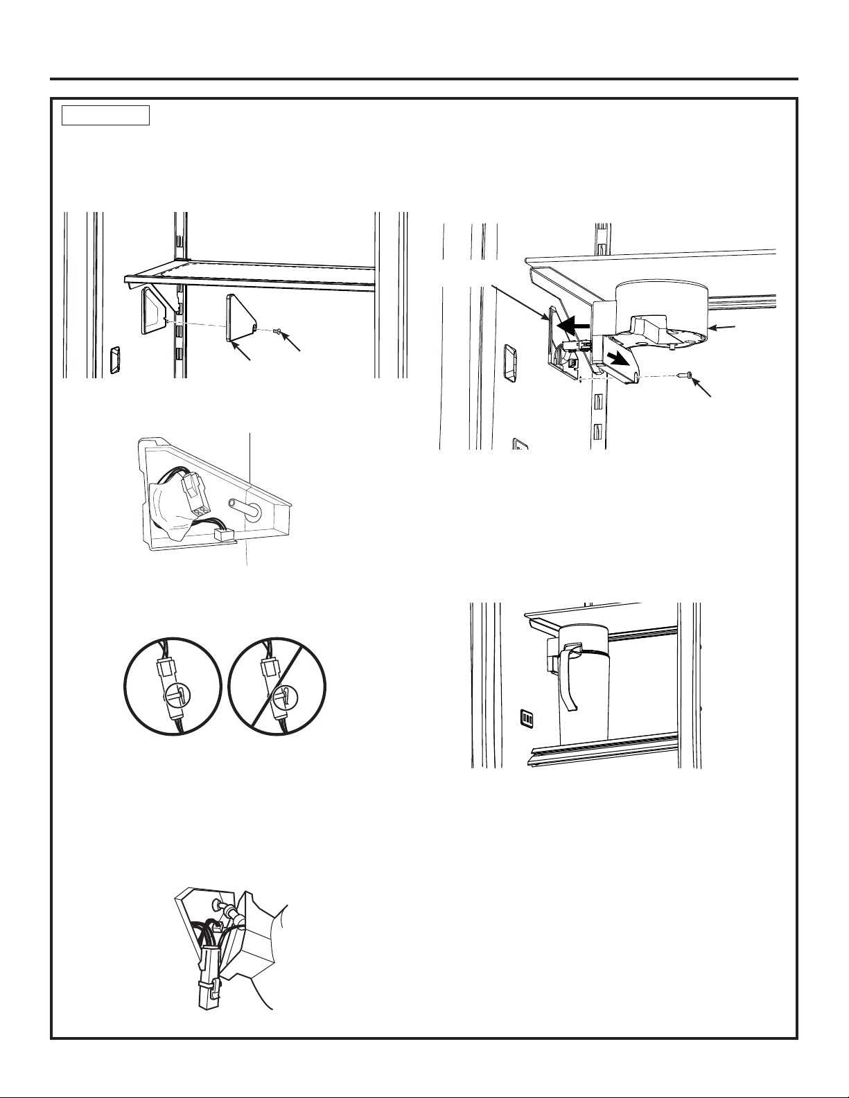
STEP 13 INSTALL AUTOFILL PITCHER ASSEMBLY (Some Refrigerator Models)
Ŷ Locate the AutoFill pitcher cover on the left side of the
refrigerator’s interior. Remove T20 Torx screw holding
the cover in place towards the rear of the cover. Retain
this screw for attachment of AutoFill assembly.
Cover
Ŷ Slide the cover forward to remove. This reveals an
electrical connector and a water tube.
Ŷ Remove the AutoFill assembly from the box. Connect
the 4 pin connector from the AutoFill assembly to the
connector in the compartment wall.
Screw
Ŷ Conceal wires and tubing inside the wall compartment
and place the AutoFill wall assembly onto the forward
end of the mount until flush with the interior wall of the
refrigerator. Slide the assembly toward the back wall
until mounting screw hole is visible.
Mount
Compartment
AutoFill
Assembly
Screw
Ŷ Secure AutoFill assembly with the T20 Torx screw
removed earlier.
Ŷ Ensure supply water is connected to the refrigerator
before proceeding further.
Ŷ Align the pitcher lid to the dispenser guide and slide
the pitcher toward the back of the refrigerator until it
stops. There may be up to a 5 second response time
before water starts to fill the pitcher.
Ŷ Ensure that the locking tab on the connector is fully
engaged.
Ŷ Connect the water line fitting from the AutoFill
assembly to the water tube located in the
compartment. Ensure the water tube is firmly
connected and will not easily become unattached.
Water tube should be inserted to the tubing mark.
31-1000190 Rev. 4
Ŷ Water will fill the pitcher until it reaches a specified
level and will then shut off. It is normal for the water
level to be below the top of the pitcher.
NOTE: After installing the AutoFill pitcher, run 2 gallons
of water (approximately 5 full pitchers) through the
AutoFill dispenser to remove air from the system. A
newly installed filter cartridge will cause water to spurt
and dribble until the air is out of the system. It is normal
for water to appear discolored during the initial system
flush. Water color will return to normal after the first
minutes of dispensing. Wash the AutoFill pitcher and lid
following the initial flush before using.
NOTE: Do not place the pitcher in the dispenser guide
before the water connection is made to the refrigerator.
23
Page 24

Instructions for Dual Retro-Fit Installation
Existing construction installation with 24” deep openings
that are 41-1/2” or 47-1/2” wide
24
31-1000190 Rev. 4
Page 25
Design Guide - Dual Retro-Fit Installation
DUAL RETRO-FIT INSTALLATION SPACE
Dimensions in parentheses are in centimeters.
*83 1/2" min
*84 1/2" max
(212.1-214.6)
*Trim will overlap
additional 7/16"
5"
(12.7)
47 1/2" (120.7)
6"
(15.2)
E
5"
(12.7)
WATER
20" (50.8)
5"
(12.7)
of electrical
3 1/2"
(8.9)
75"
(190.5 )
From floor
to bottom
area
3 1/2"
(8.9)
Finished
Return
FRONT VIEW SIDE VIEW
41 1/2" (105.4)
6"
(15.2)
E
5"
(12.7)
18" (45.7)
3 1/2"
(8.9)
Finished
Return
24" (61.0)
24" (61.0)
3/4"
(1.91)
W
*83 1/2" min
*84 1/2" max
(212.1-214.6)
*Trim will overlap
additional 7/16
"
5"
(12.7)
WATER
5"
(12.7)
3 1/2"
(8.9)
75"
(190.5 )
From floor
to bottom
of electrical
area
FRONT VIEW SIDE VIEW
Water And Electrical Locations
Electrical and water supply must be located as shown.
For 24” Deep Cutouts
Trim Retro kits are required for a 41.5”(ZKR42N) or a
47.5” (ZKR48N) wide opening.
Heater Unification Kit ZKUN required
Product Clearances
These units are equipped with a 2-position door stop.
The factory set 115° door swing can be adjusted to 90°
if clearance to adjacent cabinets or walls is restricted.
For a 90° door swing, allow 4” (10.2 cm) minimum
clearance to a wall.
When installed in a corner, allow 15” (38.1 cm) for a full
115° door swing on 18” and 24” models. Allow 16-1/2”
(41.9 cm) on 30” models.
3/4"
(1.91)
W
Additional Specifications
• A separate 115 volt 60Hz., 15 or 20 amp power supply
is recommended for each product. An individual
properly grounded branch circuit or circuit breaker is
recommended. Install a properly grounded 3-prong
electrical receptacle recessed into the back wall.
Electrical must be located on rear wall as shown.
• Water line must be located on the back wall as shown.
The water line should be 1/4” O.D. copper tubing or
QuickConnect™ kit (WX08X10006) between the cold
water line and water connection location, long enough
to extend to the front of the unit (8’ [2.4m]). Installation
of an easily accessible shut-off valve in the water line
is required.
31-1000190 Rev. 4
25
Page 26
Installation Instructions - Dual Retro-Fit Installation
REFRIGERATOR/FREEZER LOCATION
Ŷ Do not install the refrigerator/freezer where the tem-
perature will go below 55°F (13°C). It will not run
often enough to maintain proper temperatures.
Ŷ Do not install the refrigerator/freezer where
temperatures will go above 100°F (37°C). It will not
perform properly.
Ŷ Do not install the refrigerator/freezer in a location
exposed to water (rain, etc.) or direct sunlight.
Ŷ Install it on a floor strong enough to support it fully
loaded.
TOOLS AND MATERIALS REQUIRED
• Metal shears
• #1, #2 Phillips screwdriver
• Flathead screwdriver
• Putty knife
• Measuring tape
• Drill and 1/16”, 5/64”, 3/16”, 1/2” bits
• 5/32” concrete bit (if installing anti-tip into concrete)
• 1/4”, 3/8”, 7/16” driver/socket
• 7/16” open wrench
• T10, T20, T30 driver/bit
• 1/8”, 1/4” hex driver (allen wrench)
• Level
• Water shut-off valves (optional but recommended)
• 8’ waterline (one per unit requiring water hookup)
• Masking tape
• Rubbing alcohol
• Adjustable wrench
• Center punch
• Heater Unification Kit (ZKUN)
• Stainless Steel Door Kits (if applicable)
• Custom panels for doors (if applicable)
• Handle Kits (if applicable)
• Small Rachet
• 42” (ZKR42N) or 48” (ZKR48N) Trim Retro Kit
• 42” (ZKK42P) or 48” (ZKK48P) Stainless Steel Toe
Kick
GROUNDING THE UNIT
WARNING
Hazard. Failure to follow these instructions can
result in death, fire, or electrical shock.
The power cord of this appliance is equipped with a
3-prong (grounding) plug which mates with a standard
3-prong (grounding) wall receptacle to minimize the
possibility of electric shock hazard from this appliance.
Have the wall outlet and circuit checked by a qualified
electrician to make sure the outlet is properly grounded.
Where a standard 2-prong wall outlet is encountered, it
is your personal responsibility and obligation to have it
replaced with a properly grounded 3-prong wall outlet.
DO NOT, UNDER ANY CIRCUMSTANCES,
CUT OR REMOVE THE THIRD (GROUND)
PRONG
FROM THE POWER CORD.
DO NOT USE AN ADAPTER PLUG TO
CONNECT THE REFRIGERATOR TO A
2-PRONG OUTLET.
DO NOT USE AN EXTENSION CORD WITH
THIS APPLIANCE.
Electrical Shock
FLOORING
For proper installation, this product must be placed
on a level surface of hard material that is at the same
height as the rest of the flooring. This surface should
be strong enough to support a fully loaded refrigerator
or freezer, or approximately 1,200 lbs. per unit.
NOTE: Protect the finish of the flooring.
NOTE: Not recommended for installation on carpeted
flooring.
HARDWARE SUPPLIED (per unit)
• Water Filter Bypass Plug (if equipped)
• Air filter (if equipped)
• Anti-Tip bracket
• 3 Lag screws
• 3 Tapcon screws
• 3 Toggles with bolts
• Panel installation templates
• 2 Door trims
• 2 Door panel brackets
• Set screws
• #6 Phillips head wood screws
• Door Bracket Cover Top
• T30 screws
• 1 Hinge limiter pin
• Center door panel bracket
• Hi-Lo screw and square washer
• Access Cover
• Painted access cover screws
• T10 screws
26
31-1000190 Rev. 4
Page 27
Installation Instructions - Dual Retro-Fit Installation
KIT ZKUN PARTS SUPPLIED:
Adhesive Heater
Transformer
Front Mullion
Trim Bracket
Top Unification Bracket
Bottom Front Unification Bracket
3 1/4” Hex Head 8-18 5/8” Long Screws
5 1/4” Hex Head 8-32 5/8” Long Screws
5 3/8” Hex Head 1/4-20 1/2” Long Screws
4 wire clips
Tools and Materials Required:
1/4” and 3/8” driver / sockets
#2 Phillips screwdriver
Rubbing alcohol
STEP 1 REMOVE PACKAGING
WARNING
appliance is top heavy. Use extreme caution with
moving to prevent tipping over which could result in
death or serious injury.
Tip Over Hazard. This
STEP 1 REMOVE PACKAGING
(Cont.)
Ŷ Remove front access cover from unit by removing
two 1/4” Hex Screws (some models have access
cover in a box on the left side of the cabinet).
Place the cover and screws to the side for future
installation.
Ŷ Remove three 3/8” drive screws and two 7/16” drive
screws from each side of the unit to release it from
the shipping skid. Tip the unit from the side enough
to remove the shipping material from under the unit,
but above the shipping skid (both sides)
Ŷ CAREFULLY roll the unit off the back side of the
shipping skid.
Ŷ Handle from side only with a hand truck.
3/8” Drive
Screws
Shipping
Bracket
7/16” Drive
Screws
1/4” Hex Screws
Ŷ Remove outer carton and external packing from units.
Ŷ Inspect for damage.
Ŷ If installation will require the door swing to be
reversed, follow the instructions in Reversing the
Door Swing section to reverse the door swing
BEFORE the unit is removed from the shipping skid.
Ŷ Ensure the flooring that the units are set is clean/
free of debris that could be collected on to, or
pinched in front of the wheels and damaging the
floor. Additionally, it is recommended that the floor
be protected with a plastic covering through out the
installation process.
Ŷ Remove hardware kit from top drawer.
Ŷ If installation requires a 90
limiter pin must be installed
in the top hinge BEFORE
the unit is removed from the
shipping skid. Pin is located in
the hardware kit.
- Open the door approximately
45°, but no wider than 90°,
to expose the hole in the
back hinge bracket and
install the limiting pin. Pin
must be fully seated in the
bracket or the door will not close properly.
° door opening, the hinge
Top
hinge
STEP 2 INSTALL WATER LINE
WARNING
only. A cold water supply is required for automatic
icemaker operation. The water pressure must be
between 40 and 120 psi (275-827 kilopascals).
WARNING
Attach tubing clamp using existing hole only. DO
NOT drill into the refrigerator.
Ŷ
A cold water supply is required for automatic icemaker
and AutoFill pitcher operation. The water pressure
must be between 40 and 120 p.s.i. (275-827 kPa).
Shut off the main water supply.
Turn on the nearest faucet long enough to clear the
line of water.
ŶInstall a shut-off valve between the water valve and
cold water pipe in a basement or cabinet. The shutoff valve should be located where it will be easily
accessible.
ŶTurn on the main water supply and flush debris.
Run about a quart of water through the tubing into a
bucket. Shut off water supply at the shut-off valve.
Connect to potable water supply
ELECTRIC SHOCK HAZARD
31-1000190 Rev. 4
27
Page 28
Installation Instructions - Dual Retro-Fit Installation
STEP 2 INSTALL WATER LINE
(Cont.)
NOTE: Saddle type shut-off valves are included in
many water supply kits. Before purchasing, make sure
a saddle type valve complies with your local plumbing
codes.
NOTE: Commonwealth of Massachusetts Plumbing
Codes 248CMR shall be adhered to. Saddle
valves are illegal and use is not permitted in
Massachusetts. Consult with your licensed plumber.
Ŷ Connect the jumper water line from the ZKR42N or
ZKR48N Trim Retro Kit to the house cold water line.
Tighten the compression nut hand tight, then tighten
one additional turn with a wrench. Overtightening
can cause leaks!
Ŷ Connect the other end of the jumper water line to the
water fitting tee supplied in the trim retro kit. Tighten
the compression nut hand tight, then tighten one
additional turn with a wrench. Overtightening can
cause leaks!
Water Line Jumper
STEP 3 PREPARING UNIT FOR
INSTALLATION
Ŷ Unpack the heater Unification Kit (ZKUN) and make
sure all of the components on the list are included.
NOTE: Ensure the heater connector cord is toward the
top of the unit when installed.
Ŷ Place the right hand unit in front of the installation
opening in a way that the unit is in front of the
intended installed location.
Ŷ
Install adhesive heater on the outside of the unit to the
left side of the case. Install heater 4” below the case
top. Heater should be centered front to back on the
metal case.
Clips
4”
Water Fitting Tee
Ŷ Route 1/4” OD copper or SmartConnect™
(WX08X10006) plastic tubing between water fitting
tee and the water connection location at the front of
the unit.
SmartConnect™ Refrigerator Tubing Kits are
available. One 8’ (2.4m) water line (WX08X10006) is
needed for each unit.
Ŷ Tubing should be long enough to extend to the front
of the unit. Allow enough tubing to accommodate
bend leading into the water line connection. Unit
must be tipped on its side to route waterline
underneath and to the front of the appliance.
NOTE: The only GE Appliances approved plastic
tubing is supplied in the SmartConnect™ Refrigerator
Tubing kits. Do not use any other plastic water supply
line because the line is under pressure at all times.
Other types of plastic may crack or rupture with age
and cause water damage to your home.
Ŷ Tape the jumper waterline and water fitting tee to the
back wall. The waterlines will be taped to the floor
using masking tape after anti-tip bracket installation.
Adhesive
Heater
WARNING
Electrical Shock
Hazard. To avoid the risk of electric shock, make
sure the power cord is not plugged into the wall outlet.
Ŷ Install the transformer into the case top assembly:
1. Remove cover top by removing eight #8 hex screws
and keep aside for assembling back the cover top.
2. Place the transformer into the case top provided in
ZKUN kit and secure it with the existing (1/4”) hex
screws to left front of case top.
3. Connect the 2 pin transformer connector to the
heater connector and 3 pin connector to panel
control, make sure locking tabs are engaged.
4. NOTE: Verify the master switch is on.
5. Assemble the cover top with screws save from
previous step.
28
31-1000190 Rev. 4
Page 29
Installation Instructions - Dual Retro-Fit Installation
STEP 3 PREPARING UNIT FOR INSTALLATION (Cont.)
#8 Hex Screws
2 Pin
Connector
to Heater
Connector
Do NOT Remove
Wire Standoff
Transformer
3 Pin
Connector
Enclosure assembly upper
is hidden for clarity.
Master Switch
STEP 4
WARNING
INSTALL ANTI-TIP BRACKET
Tip Over Hazard.
These appliances are top heavy, especially with
any doors open, and must be secured to prevent
tipping forward which could result in death or serious injury. Read and follow the entire installation
instructions for securing the appliance with the
anti-tip system.
Ŷ Remove the anti-tip bracket from the hardware kit.
Ŷ Anti-tip bracket should be mounted against the back
wall or up to 27” (68.6 cm) maximum from front of
opening. Use floor mounting method if the bracket is
not against a wall (bracket hardware is provided for
mounting into wood, steel studs and concrete).
LH Unit
18” 24” 30”
26-5/8”
67.6 cm
32-5/8”
82.8 cm
38-5/8”
98.1 cm
23-1/2”
59.7 cm
29-1/2”
74.9 cm
35-1/2”
90.1 cm
23-1/2”
59.7 cm
29-1/2”
74.9 cm
35-1/2”
90.1 cm
RH UNIT
8-7/8”
22.5 CM
5-3/4”
14.5 CM
5-3/4”
14.5 CM
18”
24”
30”
Ŷ Measure and mark from the RH side of the opening per
the table above depending on the size of the RH unit
you are installing.
Cover Top
Ŷ Measure and mark again from the RH side of
the opening per the table and depending on your
combination of LH and RH units.
For example, if installing an 18” LH unit and a 30” RH
unit, use 5-3/4” and 38-5/8”.
Ŷ Mount the anti-tip bracket centered about the marks
and flush to the floor as shown. Mark 3 holes for wall
mounting or 4 holes for floor mounting.
WOOD MOUNTING: Predrill with 3/16” drill bit, 2” deep,
then install lag bolts with a 7/16” driver.
CONCRETE MOUNTING: Predrill with a 5/32” concrete
bit, 2” deep, then install tapcon screws with a 7/16”
driver.
STEEL MOUNTING: Predrill with a 1/2”
drill bit, insert toggle, then install bolts
with a 7/16” driver.
The bracket must be screwed to either
the FLOOR or REAR WALL.
Ŷ The anti-tip bracket should be secured
to the floor 23” from the front of the enclosure.
Ŷ Tape the waterline to the floor approximately 3” to the
left of the anti-tip bracket. Apply tape about every 5”
toward the front of the opening (tape will prevent the
unit from rolling over the waterline during installation).
Do not tape near the cabinet front in order to keep tape
hidden under the unit.
31-1000190 Rev. 4
LH Unit
RH Unit
29
3"
5"
3"
5"
Anti-tip Brackets
Page 30
Installation Instructions - Dual Retro-Fit Installation
STEP 5
BOTTOM BACK UNIFICATION
Ŷ Loosen the two bottom screws of rear access covers of
both units and remove the top screws.
Ŷ Hang the unification bracket to the bottom screws and
reassemble the screws at the top
Ŷ Tighten screws to tie units together.
BOTTOM FRONT UNIFICATION
Ŷ Install the bottom front unification bracket using a 3/8”
driver (4 screws).
JOINING DUAL INSTALLED UNITS
8QL¿FDWLRQ
Bracket
TOP UNIFICATION
Ŷ/RRVHQWKHPLGGOHWZRVFUHZVUHPRYHWKHWZRUHDU
screws.
Ŷ$VVHPEOHWKHEUDFNHWWRWKHPLGGOHVFUHZVDQG
reassemble the rear screws.
Ŷ7LJKWHQVFUHZVWRWLHXQLWVWRJHWKHU
8QL¿FDWLRQ
Bracket
8QL¿FDWLRQ%UDFNHW
Front of appliances
30
31-1000190 Rev. 4
Page 31

Installation Instructions - Dual Retro-Fit Installation
STEP 5 JOINING DUAL INSTALLED UNITS (Cont.)
CHANGE POWER CORD
Longer power cords are required for retro fit installation.
Power cords are included in 42” ZKR42N and 48” ZKR48N.
Replace power cords on both units. Both units can be
plugged into the same electrical supply receptacle.
Remove existing short power cord with string
assembly:
Ŷ Remove 1/4” hex screws attaching rear access cover.
1. Unplug 3-pin power cord connector inside the
machine compartment (press on sides to release
locking tabs).
2. Remove power cord green ground 1/4” hex screw.
3. Remove strain relief 1/4” hex screw.
Step 1
3-Pin
Step 2
Green Ground
Screw
Step 3
Strain Relief
Screw
Power Cord
Connector
3-Pin
Power Cord
Connector
CASE TRIM INSTALLATION
Ŷ Install the trim kit side rails to the exposed right and left
case walls using the provided #8 Phillips head screws 7 screws per side.
Rear
Access
Cover
Install new longer power cord:
1. Plug in the 3-pin connector (make sure locking tabs
are engaged).
2. Install the power cord green ground screw.
3. Install the power cord strain relief.
WARNING
Electrical Shock Hazard.
To avoid the risk of electric shock, make sure to re-install
the ground screw after changing the power cord.
Ŷ Replace rear access cover. Make sure the power
cord and ground wire are properly routed through the
access cover cut-out.
Repeat all steps for second unit.
Step 2
Ground
Step 3
Wire
Power
Cord
Ŷ Pre-assemble the trim kit top rail and corner keys. One
corner key should be installed to each end of the top
trim. Use the provided #6 Phillips head screw in the
corner key to ensure that the key is snugly fit to the
top trim, but be sure not to overtighten the screw to
prevent damage to the parts.
Corner Key
31-1000190 Rev. 4
31
Page 32

Installation Instructions - Dual Retro-Fit Installation
STEP 5 JOINING DUAL INSTALLED
UNITS (Cont.)
CASE TRIM INSTALLATION
Ŷ Fit the top trim and side trim rails together by sliding
the exposed edges of the corner trim into the right
and left trim kit side rails. Press downward on the
top trim until each corner key is fully seated in each
side rail. Use the provided #6 Phillips head screws to
ensure each corner key is snugly fit to each trim kit
side rail.
Top Trim
with Keys
STEP 6
CONNECTING WATER
SUPPLY
WARNING
only. A cold water supply is required for automatic
icemaker operation. The water pressure must be
between 40 and 120 psi (275-827 kilopascals).
WARNING
Attach tubing clamp using existing hole only. DO
NOT drill into the refrigerator.
Ŷ Locate and bring the tubing to the front of the cabinet.
Ŷ Turn the water on to flush debris from the line. Run
about a quart of water through the tubing into a
bucket, then shut off the water.
Ŷ Remove strain relief screw to allow for enough slack
to make a proper water connection. (Screw must be
replaced in the next step.)
Strain Relief
Screw
Connect to potable water supply
ELECTRIC SHOCK HAZARD
House
Water Supply
Refrigerator/
Freezer
Freezer
Water Supply
Water Supply
Ŷ Secure the top trim to the case by using the provided
#8 Phillips head screws (6 screws).
Copper Tubing:
Ŷ Slip a 1/4” nut and ferrule (provided) over both ends
of the copper tubing. Insert the tube into the union
fitting on the unit and tighten the nut to the union.
Ŷ Turn on the water to check for leaks.
SmartConnect™ Tubing:
NOTE: The only GE Appliances-approved plastic tubing
is supplied in the SmartConnect™ Refrigerator Tubing
kits. Do not use any other plastic water supply line
because the line is under pressure at all times. Other
types of plastic may crack or rupture with age and
cause water damage to your home.
Ŷ Insert the molded end of the tubing into the
refrigerator or freezer connection. Tighten the
compression nut until it is just hand-tight.
Ŷ Follow the instructions provided with the tubing.
Overtightening can cause leaks!
Ŷ Turn on the water to check for leaks.
32
31-1000190 Rev. 4
Page 33

Installation Instructions - Dual Retro-Fit Installation
STEP 7
Ŷ Plug both units to the outlet in the wall.
WARNING
To reduce the risk of electrical shock, be careful
during the remaining installation steps not to
touch wiring or electrical components inside the
compressor compartment while the appliance is
plugged in and the front access cover is not in
place.
Ŷ Find the installation string that is attached to the door
of the unit; this is to be used as you are pushing the
unit back into the opening. The string is attached to the
power cord; as you walk the unit back into the opening
you should pull the string tight to make sure the power
cord is routed underneath the unit.
INSERTING/SECURING INTO CABINET SURROUND
Electrical Shock Hazard.
Installation
String
Ŷ Place power cord on its edge and pull under product
between rollers and away from the anti-tip bracket to
ensure cord is not damaged during installation.
Ŷ As you walk the unit back into the opening, you should
pull the string tight to make sure the power cord is routed underneath the unit.
String
Ŷ Replace the waterline strain relief screw.
Strain Relief
Screw
Power Cord
Ŷ Slowly walk both units into opening making sure not
to touch the cabinetry on the sides and top to prevent
damage. The back side of the top and side retro trims
should be touching the cabinet surround when the
units are pushed back.
Refrigerator
or Freezer
Retro Trim
WARNING
These appliances are top heavy, especially with any
doors open, and must be secured to prevent tipping
forward which could result in death or serious injury.
Tip Over Hazard.
Cabinet
Surround
Ŷ Store the excess strapping, string, and water tubing
under the unit.
WARNING
Replace waterline strain relief in front rail location as
shown.
Electrical Shock Hazard.
31-1000190 Rev. 4
33
Page 34

Installation Instructions - Dual Retro-Fit Installation
STEP 8 LEVEL UNIT
All models have 4-point leveling. The front is supported
by leveling legs; the rear is supported by adjustable
wheels. Both are accessible from the front of the unit.
Ŷ To level the back of the unit, turn the 7/16” hex nut
located above the front wheels. Turn clockwise to
raise or counterclockwise to lower the unit.
Ŷ For front leveling, use a 7/16” open-end wrench.
Ŷ Adjust height of unit to match installation cutout
opening 84”. The unit should be level and plumb with
cabinetry.
Hex nut adjusts
rear wheels
Open-end wrench
adjusts front
leveling legs
NOTICE: The rear leveling wheels and front leveling
legs are limited to a maximum height adjustment of 1”.
If the installation requires more than 84” height, the
installer should elevate the unit on a sheet of plywood
or runners. Cabinetry trim could also be added across
the top of the opening to shorten the opening. If you
attempt to raise the unit more than 1”, you will damage
the front leveling legs and the rear leveling wheels.
STEP 9
FINAL EXTERNAL UNIT
PREPARATION (Cont.)
Ŷ Make sure lights are on inside the unit. If they are not
on, check to make sure the master switch is on by
removing the front enclosure which is secured with
six 1/4” Hex screws.
Ŷ Switch on the master switch if not on. (Master Switch
Wires hidden for clarity.
Ŷ Assemble the enclosure with removed screws.
Ŷ Predrill 1/16” holes is both the sides of the surround
1/2” deep through holes in the enclosure.
Ŷ Secure unit by driving four 1/4” hex screws to both
sides to surrounding cabinetry. NOTE: This step
does NOT replace the anti-tip safety hardware. Refer
to Step 4 Installing Anti-Tip Bracket and Step 7
Inserting/Securing into Cabinet Surround for details
on installing the anti-tip hardware. Repeat for the
second unit.
1/4” Hex Screws
Master Switch
1/4” Hex Screws
STEP 9
FINAL EXTERNAL UNIT
PREPARATION
Ŷ Open the doors to
the units. Locate
¿OWHUDQG¿OWHU
removal tool. Filter
should be as shown.
Ŷ5RWDWH¿OWHUóWXUQ
counterclockwise
XVH¿OWHUUHPRYDO
tool if needed).
Ŷ3XOO¿OWHUWRZDUG\RXWR
remove. NOTE: Water
system will not function
ZLWKRXW¿OWHULQSODFH
Compartment Door
Filter
Filter Removal Tool
Mounting
Hook
Ŷ Locate blue arrow on
¿OWHU5RWDWH¿OWHUWR
align arrow as shown.
Ŷ,QVHUW¿OWHULQWRSRVLWLRQ
DQGURWDWHóWXUQ
FORFNZLVHXVH¿OWHU
removal tool if needed).
Ŷ5HWXUQ¿OWHUUHPRYDOWRROWR
mounting hook.
Ŷ Close the compartment door.
34
31-1000190 Rev. 4
Page 35

Installation Instructions - Dual Retro-Fit Installation
STEP 9
FINAL EXTERNAL UNIT PREPARATION (Cont.)
Ŷ For proper case placement after leveling, the back side
of the top and side retro trims should be flush with the
cabinet surround on all sides.
Refrigerator
or Freezer
Retro Trim
Cabinet
Surround
Ŷ Secure the trims to the surrounding cabinets to reduce
excess movement to the top of the case during normal
operation.
2 on
each
side
Ŷ Put the access cover back onto the unit and secure with
two 1/4” hex head screws.
Access
Cover
1/4” Hex
Screws
Ŷ Install front mullion trim between the two units. Open
Doors and push the flexible dart in the area between
units.
Upper Mullion
Trim
Top Dart
“Dart”
1. Drill 1/16” pilot holes in the trim 1/2” deep(2 per side,
see figure for approximate locations).
2. Drive #6 Phillips head wood screws into the pilot
holes.
NOTE: This step does NOT replace the anti-tip safety
hardware. Refer to Step 4 Installing Anti-Tip Bracket
and Step 7 Inserting/Securing into Cabinet Surround for
details on installing the anti-tip hardware. Repeat for the
second unit.
Ŷ Verify the two 1/4” hex head screws are assembled to
handle side of the products for both freezer and fresh
food columns.
1/4” Hex Screws
Ŷ Top dart of the mullion must align with bottom edge of
the case trim.
Ŷ Open both water filter access doors to 90°.
Ŷ Snap the trim bracket between the water filter access
enclosures above displays.
Trim
31-1000190 Rev. 4
35
Page 36

Installation Instructions - Dual Retro-Fit Installation
STEP 10 TOE KICK INSTALLATION
Ŷ Insert Toe Kick into the slot in the Front Access
Cover by rotating it toward you.
Ŷ Push the bottom
portion of the Toe
Kick towards the
product and slide
into place.
STEP 11 INTERNAL UNIT
PREPARATION
Ŷ Remove all tape, cardboard, and foam from each unit
(foam shipping supports may be located behind the
left and right sides of each of the glass pan fronts on
Refrigerator models).
Ŷ Remove boxed door bins from shelves.
Ŷ Unbox and install door bins.
Ŷ Install door bin mats.
STEP 12 START ICEMAKER
(freezer models)
CAUTION
injury, avoid contact with the moving parts of the
ejector mechanism, or with the heating element that
releases the cubes. Do not place fingers or hands on
the automatic ice making mechanism while the
appliance is plugged in.
A newly-installed freezer may take 12–24 hours to
begin making ice.
The icemaker will produce seven cubes per cycle—
approximately 15 cycles in a 24-hour period,
depending on freezer compartment temperature, room
temperature, number of door openings and other use
conditions.
If the freezer is operated before the water connection
is made to the icemaker, set the power switch to
OFF. Top wire basket must be removed to access the
icemaker power switch.
When the freezer has been connected to the water
supply, set the power switch to ON.
To minimize the risk of personal
Throw away the first full bucket of ice to allow the water
line to clear.
Be sure nothing interferes with the sweep of the feeler
arm.
(Appearance may vary)
Icemaker
Power
Switch
When the bin fills to the level of the feeler arm, the
icemaker will stop producing ice.
It is normal for several cubes to be joined together.
If ice is not used frequently, old ice cubes will become
cloudy, taste stale and shrink.
NOTE: Icemaker works best between 40 and 120 PSI
(275-827 kPa) home water pressure.
Feeler Arm
Power
Switch
Icemaker
Feeler Arm
36
31-1000190 Rev. 4
Page 37

Installation Instructions - Dual Retro-Fit Installation
STEP 13 INSTALL AUTOFILL PITCHER ASSEMBLY (Some Refrigerator Models)
Ŷ Locate the AutoFill pitcher cover on the left side of the
refrigerator’s interior. Remove T20 Torx screw holding
the cover in place towards the rear of the cover. Retain
this screw for attachment of AutoFill assembly.
Cover
Ŷ Slide the cover forward to remove. This reveals an
electrical connector and a water tube.
Ŷ Remove the AutoFill assembly from the box. Connect
the 4 pin connector from the AutoFill assembly to the
connector in the compartment wall.
Screw
Ŷ Conceal wires and tubing inside the wall compartment
and place the AutoFill assembly onto the forward end
of the mount until flush with the interior wall of the
refrigerator. Slide the assembly toward the back wall
until mounting screw hole is visible.
Mount
Compartment
AutoFill
Assembly
Screw
Ŷ Secure AutoFill assembly with the T20 Torx screw
removed earlier.
Ŷ Ensure supply water is connected to the refrigerator
before proceeding further.
Ŷ Align the pitcher lid to the dispenser guide and slide
the pitcher toward the back of the refrigerator until it
stops. There may be up to a 5 second response time
before water starts to fill the pitcher.
Ŷ Ensure that the locking tab on the connector is fully
engaged.
Ŷ Connect the water line fitting from the AutoFill
assembly to the water tube located in the
compartment. Ensure the water tube is firmly
connected and will not easily become unattached.
Water tube should be inserted to the tubing mark.
31-1000190 Rev. 4
Ŷ Water will fill the pitcher until it reaches a specified
level and will then shut off. It is normal for the water
level to be below the top of the pitcher.
NOTE: After installing the AutoFill pitcher, run 2 gallons
of water (approximately 5 full pitchers) through the
AutoFill dispenser to remove air from the system. A
newly installed filter cartridge will cause water to spurt
and dribble until the air is out of the system. It is normal
for water to appear discolored during the initial system
flush. Water color will return to normal after the first
minutes of dispensing. Wash the AutoFill pitcher and lid
following the initial flush before using.
NOTE: Do not place the pitcher in the dispenser guide
before the water connection is made to the refrigerator.
37
Page 38

Instructions for Single Integrated Installation
New construction installation with 25” deep openings
38
31-1000190 Rev. 4
Page 39

Design Guide - Single Integrated Installation
SINGLE INTEGRATED INSTALLATION SPACE
Dimensions in parentheses are in centimeters.
18” Integrated Freezer 30” Integrated Freezer or Refrigerator
17 13/16" (45.2)
3 1/2"
(8.9)
Finished
Return
25" (63.5)
29 13/16" (75.7)
3 1/2"
(8.9)
Finished
Return
25" (63.5)
84"
(213.4)
4 1/8"
(10.5)
6 3/4"
(17.2)
3 1/2"
(8.9)
7 1/2 2
E
FRONT VIEW
4"
W
(10.2)
2 1/2"
(6.4)
SIDE VIEW
Back
24” Integrated Freezer or Refrigerator
25" (63.5)
Back
SIDE VIEW
84"
(213.4)
9 1/2"
(24.1)4"(10.2)
4 3/8"
(11.1)
ELEC W
FRONT VIEW
23 13/16" (60.5)
5"
(12.7)
6 3/4"
(17.2)
2 1/2"
(6.4)
3 1/2"
(8.9)
Finished
Return
Product Clearances
These units are equipped with a 2-position door stop.
The factory set 115° door swing can be adjusted to 90° if
clearance to adjacent cabinets or walls is restricted.
For a 90° door swing, allow 4” (10.2 cm) minimum
clearance to a wall.
When installed in a corner, allow 15” (38.1 cm) for a full
115° door swing on 18” and 24” models. Allow 16-1/2”
(41.9 cm) on 30” models.
84"
(213.4)
10 1/4"
6 1/4"
(26.0)
4 3/8"
(11.1)
ELEC W
(12.7)
FRONT VIEW
(15.9)
5"
6 3/4"
(17.2)
2 1/2"
(6.4)
SIDE VIEW
Back
Water And Electrical Locations
Electrical and water supply must be located as shown.
The Cutout Depth Must Be 25”.
Additional Specifications
Ŷ A 115 volt 60Hz., 15 or 20 amp power supply is
required. An individual properly grounded branch circuit
or circuit breaker is recommended. Install a properly
grounded 3-prong electrical receptacle recessed into
the back wall. Electrical must be located on rear wall as
shown.
Ŷ Water line must be located on the back wall as shown.
The water line should be 1/4” O.D. copper tubing or
QuickConnect
™
kit (WX08X10006) between the cold
water line and water connection location, long enough
to extend to the front of the unit (8’ [2.4 m]). Installation
of an easily accessible shut-off valve in the water line is
required.
Ŷ A minimum of 3-1/2” (8.9cm) finished return matching
cabinet exterior is recommended on interior on all sides
and top at front of opening.
Ŷ Installations with 4” (10.2 cm) or less between units
require Heater Kit ZKUN.
31-1000190 Rev. 4
39
Page 40

Installation Instructions - Single Integrated Installation
REFRIGERATOR/FREEZER LOCATION
Ŷ Do not install the refrigerator/freezer where the tem-
perature will go below 55°F (13°C). It will not run
often enough to maintain proper temperatures.
Ŷ Do not install the refrigerator/freezer where
temperatures will go above 100°F (37°C). It will not
perform properly.
Ŷ Do not install the refrigerator/freezer in a location
exposed to water (rain, etc.) or direct sunlight.
Ŷ Install it on a floor strong enough to support it fully
loaded.
TOOLS AND MATERIALS REQUIRED
• Metal shears
• #1, #2 Phillips screwdriver
• Flathead screwdriver
• Putty knife
• Measuring tape
• Drill and 1/16”, 5/64”, 3/16”, 1/2” bits
• 5/32” concrete bit (if installing anti-tip into concrete)
• 1/4”, 3/8”, 7/16” driver/socket
• 7/16” open wrench
• T20, T30 driver/bit
• 1/8”, 1/4” hex driver (allen wrench)
• Level
• Water shut-off valves (optional but recommended)
• 8’ waterline (one per unit requiring water hookup)
• Masking tape
• Rubbing alcohol
• Adjustable wrench
• Center punch
• Heater Unification Kit (ZKUN) (only required with 4”
or less between units)
• Stainless Steel Door Kits (if applicable)
• Custom panels for doors (if applicable)
• Handle Kits (if applicable)
• Small Ratchet
GROUNDING THE UNIT
WARNING
Hazard. Failure to follow these instructions can
result in death, fire, or electrical shock.
The power cord of this appliance is equipped with a
3-prong (grounding) plug which mates with a standard
3-prong (grounding) wall receptacle to minimize the
possibility of electric shock hazard from this appliance.
Have the wall outlet and circuit checked by a qualified
electrician to make sure the outlet is properly grounded.
Where a standard 2-prong wall outlet is encountered, it
is your personal responsibility and obligation to have it
replaced with a properly grounded 3-prong wall outlet.
DO NOT, UNDER ANY CIRCUMSTANCES, CUT OR
REMOVE THE THIRD (GROUND) PRONG
FROM THE POWER CORD.
DO NOT USE AN ADAPTER PLUG TO
CONNECT THE REFRIGERATOR TO A
2-PRONG OUTLET.
DO NOT USE AN EXTENSION CORD WITH
THIS APPLIANCE.
Electrical Shock
FLOORING
For proper installation, this product must be placed
on a level surface of hard material that is at the same
height as the rest of the flooring. This surface should
be strong enough to support a fully loaded refrigerator
or freezer, or approximately 1,200 lbs. per unit.
NOTE: Protect the finish of the flooring.
NOTE: Not recommended for installation on carpeted
flooring.
HARDWARE SUPPLIED (per unit)
• Water Filter Bypass Plug (if equipped)
• Air filter (if equipped)
• Anti-Tip bracket
• 3 Lag screws
• 3 Tapcon screws
• 3 Toggles with bolts
• 1 Hair Pin Cotter
• 1 Retaining pin
• Panel installation templates
• 2 Door trims
• 2 Door panel brackets
• Set screws
• #6 Phillips head wood screws
• Door Bracket Cover Top
• T30 screws
• 1 Hinge limiter pin
• Center door panel bracket
• Hi-Lo screw and square washer
• Access Cover
• Painted access cover screws
40
31-1000190 Rev. 4
Page 41

Installation Instructions - Single Integrated Installation
KIT ZKUN PARTS SUPPLIED:
Adhesive Heater
Transformer
Front Mullion
Trim Bracket
Top Unification Bracket
Bottom Front Unification Bracket
3 1/4” Hex Head 8-18 5/8” Long Screws
5 1/4” Hex Head 8-32 5/8” Long Screws
5 3/8” Hex Head 1/4-20 1/2” Long Screws
4 wire clips
Tools and Materials Required:
1/4” and 3/8” driver / sockets
#2 Phillips screwdriver
Rubbing alcohol
STEP 1 REMOVE PACKAGING
WARNING
These appliances are top heavy, especially with any
doors open, and must be secured to prevent tipping
forward which could result in death or serious injury.
Tip Over Hazard.
STEP 1 REMOVE PACKAGING
(Cont.)
Ŷ Remove front access cover from unit by removing
two 1/4” hex head screws (some models have
access cover in a box on the left side of the cabinet).
Place the cover and screws to the side for future
installation.
Ŷ Remove three 3/8” drive screws and two 7/16” drive
screws from each side of the unit to release it from
the shipping skid. Tip the unit from the side enough
to remove the shipping material from under the unit,
but above the shipping skid (both sides)
Ŷ CAREFULLY roll the unit off the back side of the
shipping skid.
Ŷ Handle from side only with a hand truck.
3/8” Drive
Screws
Shipping
Bracket
7/16” Drive
Screws
Access
Cover
1/4” Hex Head
Screws
Ŷ Remove outer carton and external packing from units.
Ŷ Inspect for damage.
Ŷ If installation will require the door swing to be
reversed, follow the instructions in Reversing the
Door Swing section to reverse the door swing
BEFORE the unit is removed from the shipping skid.
Ŷ Ensure the flooring that the units are set is clean/
free of debris that could be collected on to, or
pinched in front of the wheels and damaging the
floor. Additionally, it is recommended that the floor
be protected with a plastic covering through out the
installation process.
Ŷ Remove hardware kit from top drawer.
Ŷ If installation requires a 90° door opening, the hinge
limiter pin must be installed in the top hinge BEFORE
the unit is removed from the shipping skid. Pin is
located in the hardware kit.
- Open the door approximately
45°, but no wider than 90°, to
expose the hole in the back
hinge bracket and install the
limiting pin. Pin must be fully
seated in the bracket or the
door will not close properly.
Top
hinge
STEP 2 INSTALL WATER LINE
WARNING
only. A cold water supply is required for automatic
icemaker operation. The water pressure must be
between 40 and 120 psi (275-827 kilopascals).
WARNING
Attach tubing clamp using existing hole only. DO
NOT drill into the refrigerator.
Shut off the main water supply.
Turn on the nearest faucet long enough to clear the
line of water.
ŶInstall a shut-off valve between the water valve and
cold water pipe in a basement or cabinet. The shutoff valve should be located where it will be easily
accessible.
ŶTurn on the main water supply and flush debris.
Run about a quart of water through the tubing into a
bucket. Shut off water supply at the shut-off valve.
Connect to potable water supply
ELECTRIC SHOCK HAZARD
31-1000190 Rev. 4
41
Page 42

Installation Instructions - Single Integrated Installation
STEP 2 INSTALL WATER LINE
(Cont.)
NOTE: Saddle type shut-off valves are included in
many water supply kits. Before purchasing, make sure
a saddle type valve complies with your local plumbing
codes.
NOTE: Commonwealth of Massachusetts Plumbing
Codes 248CMR shall be adhered to. Saddle
valves are illegal and use is not permitted in
Massachusetts. Consult with your licensed plumber.
Ŷ Route 1/4” OD copper or SmartConnect™
(WX08X10006) plastic tubing between house cold
water line and the water connection location at the
front of the unit.
SmartConnect™ Refrigerator
Tubing Kits are available.
One 8’ (2.4m) water line
(WX08X10006) is needed for
each unit. The waterline will
be taped to the floor using
masking tape after anti-tip
bracket installation.
Ŷ Tubing should be long enough to extend to the front
of the unit. Allow enough tubing to accommodate
bend leading into the water line connection. Unit
must be tipped on its side to route waterline
underneath and to the front of the appliance.
NOTE: The only GE Appliances approved plastic
tubing is supplied in the SmartConnect™ Refrigerator
Tubing kits. Do not use any other plastic water supply
line because the line is under pressure at all times.
Other types of plastic may crack or rupture with age
and cause water damage to your home.
STEP 3 PREPARING UNIT FOR
INSTALLATION
Ŷ Place the unit in front of the installation opening in a
way that the unit is in front of the intended installed
location.
STEP 4
WARNING
This appliance is top heavy, especially with any
doors open, and must be secured to prevent tipping
forward which could result in death or serious injury.
Read and follow the entire installation instructions
for securing the appliance with the anti-tip system.
Ŷ Remove the anti-tip bracket from the hardware kit.
Ŷ Anti-tip bracket should be mounted against the back
wall or up to 25-1/2” (64.7 cm) maximum from front of
opening. Use floor mounting method if the bracket is
not against a wall (bracket hardware is provided for
mounting into wood, steel studs and concrete).
Unit From Enclosure
18” 8-7/8” (22.5 cm)
24” 5-3/4” (14.6 cm)
30” 5-3/4” (14.6 cm)
Ŷ Measure and mark from the right side of the opening
per the table depending on the size of the unit you
are installing.
Ŷ Mount the anti-tip bracket centered about the mark
and flush to the floor as shown. Mark 3 holes for wall
mounting or 4 holes for floor mounting.
WOOD MOUNTING: Predrill with 3/16” drill bit, 2”
deep, then install lag bolts with a 7/16” driver.
CONCRETE MOUNTING: Predrill with a 5/32”
concrete bit, 2” deep, then install tapcon screws with
a 7/16” driver.
STEEL MOUNTING: Predrill with a
1/2” drill bit, insert toggle, then install
bolts with a 7/16” driver.
The bracket must be screwed to
either the FLOOR or REAR WALL.
Ŷ If the enclosure is deeper than 25
½”, the anti-tip bracket should be
secured to the floor 25” from front of the enclosure.
Ŷ Tape the waterline to the wall and floor approximately
3” to the left of the anti-tip bracket. Apply tape about
every 5” toward the front of the opening (tape will
prevent the unit from
rolling over the waterline
during installation). Do
not tape near the cabinet
front in order to keep tape
hidden under the unit.
INSTALL ANTI-TIP BRACKET
Tip Over Hazard.
3"
5"
42
31-1000190 Rev. 4
Page 43

Installation Instructions - Single Integrated Installation
STEP 5
WARNING
only. A cold water supply is required for automatic
icemaker operation. The water pressure must be
between 40 and 120 psi (275-827 kilopascals).
WARNING
Attach tubing clamp using existing hole only. DO
NOT drill into the refrigerator.
Ŷ Locate and bring the tubing to the front of the cabinet.
Ŷ Turn the water on to flush debris from the line. Run
about a quart of water through the tubing into a
bucket, then shut off the water.
Ŷ Remove strain relief screw to allow for enough slack
to make a proper water connection. (Screw must be
replaced in the next step.)
CONNECT WATER SUPPLY
Connect to potable water supply
ELECTRIC SHOCK HAZARD
Refrigerator/
Freezer
Freezer
Water Supply
Water Supply
Water Supply
Strain Relief
Screw
House
STEP 6 INSERTING/SECURING
INTO CABINET SURROUND
Ŷ Plug unit into the outlet in the wall.
WARNING
To reduce the risk of electrical shock, be careful
during the remaining installation steps not to touch
wiring or electrical components inside the compressor
compartment while the appliance is plugged in and
the front access cover is not in place.
Ŷ Find the installation
string that is attached
to the door of the unit;
this is to be used as
you are pushing the
unit back into the
opening. The string is
attached to the power
cord; as you walk the
unit back into the opening you should pull the string
tight to make sure the power cord is routed underneath the unit.
Ŷ Slowly walk the unit into opening making sure not to
touch the cabinetry on the sides and top to prevent
damage. Door face should be 7/8” behind the front
face of surrounding cabinets on either a stainless or
custom panel installation.
WARNING
This appliance is top heavy, especially with the
door open, and must be secured to prevent tipping
forward which could result in death or serious injury.
Electrical Shock Hazard.
Installation
String
Tip Over Hazard.
Copper Tubing:
Ŷ Slip a 1/4” nut and ferrule (provided) over both ends
of the copper tubing. Insert the tube into the union
fitting on the unit and tighten the nut to the union.
Ŷ Turn on the water to check for leaks.
SmartConnect™ Tubing:
NOTE: The only GE Appliances-approved plastic
tubing is supplied in the SmartConnect™ Refrigerator
Tubing kits. Do not use any other plastic water supply
line because the line is under pressure at all times.
Other types of plastic may crack or rupture with age
and cause water damage to your home.
Ŷ Insert the molded end of the tubing into the
refrigerator or freezer connection. Tighten the
compression nut until it is just hand-tight.
Ŷ Follow the instructions provided with the tubing.
Overtightening can cause leaks!
Ŷ Turn on the water to check for leaks.
31-1000190 Rev. 4
Ŷ Place power cord on its edge and pull under product
between rollers and away from the anti-tip bracket to
ensure cord is not damaged during installation.
String
Ŷ As you walk the unit back into the opening, you
should pull the string tight to make sure the power
cord is routed underneath the unit.
Ŷ Replace the
waterline strain
relief screw.
Ŷ Store the
excess string
and water tubing
under the unit.
WARNING
Replace waterline strain relief in front rail location as
shown.
Strain Relief
Screw
Electrical Shock Hazard.
Power Cord
43
Page 44

Installation Instructions - Single Integrated Installation
STEP 7 LEVEL UNIT
All models have 4-point leveling. The front is supported
by leveling legs; the rear is supported by adjustable
wheels. Both are accessible from the front of the unit.
Ŷ To level the back of the unit, turn the 7/16” hex
nut located above the front wheels. Turn clockwise
to raise or
counterclockwise
to lower the unit.
Ŷ For front leveling,
use a 7/16” openend wrench.
Ŷ Adjust height
of unit to match
installation cutout
opening 84”. The
unit should be
level and plumb
with cabinetry.
NOTICE: The rear leveling wheels and front leveling
legs are limited to a maximum height adjustment of 1”.
If the installation requires more than 84” height, the
installer should elevate the unit on a sheet of plywood
or runners. Cabinetry trim could also be added across
the top of the opening to shorten the opening. If you
attempt to raise the unit more than 1”, you will damage
the front leveling legs and the rear leveling wheels.
STEP 8
FINAL EXTERNAL UNIT
Hex nut adjusts
rear wheels
Open-end wrench
adjusts front
leveling legs
PREPARATION
FOR FLUSH INSTALLATION: Make sure front surface
of the door is 7/8” behind front face of surrounding
cabinets BEFORE securing brackets to the surrounding
cabinetry.
Ŷ Open the doors to
the units. Locate
¿OWHUDQG¿OWHU
removal tool.
Filter should be as
shown.
Ŷ5RWDWH¿OWHUóWXUQ
counterclockwise (use
¿OWHUUHPRYDOWRROLI
needed).
Ŷ3XOO¿OWHUWRZDUG\RXWR
remove. NOTE: Water
V\VWHPZLOOQRWIXQFWLRQZLWKRXW¿OWHULQSODFH
Compartment Door
Filter
Mounting
Hook
Filter Removal Tool
STEP 8
FINAL EXTERNAL UNIT
PREPARATION (Cont.)
Ŷ Make sure lights are on inside the unit. If they are not
on, check to make sure the master switch is on by
removing the front enclosure which is secured with
six 1/4” Hex screws.
1/4” Hex Screws
Ŷ Switch on the master switch if not on. (Master Switch
Wires hidden for clarity.
Master Switch
Ŷ Assemble the enclosure with removed screws.
Ŷ Predrill 1/16” holes is both the sides of the surround
1/2” deep through holes in the enclosure.
Ŷ Secure unit by driving four 1/4” hex screws to both
sides to surrounding cabinetry. NOTE: This step does
NOT replace the anti-tip safety hardware. Refer to
Step 4 Installing Anti-Tip Bracket and Step 7 Inserting/
Securing into Cabinet Surround for details on installing
the anti-tip hardware. Repeat for the second unit.
Ŷ/RFDWHEOXHDUURZRQ¿OWHU5RWDWH¿OWHUWRDOLJQDUURZ
as shown.
Ŷ,QVHUW¿OWHULQWRSRVLWLRQDQGURWDWH
óWXUQFORFNZLVHXVH¿OWHUUHPRYDO
tool if needed).
Ŷ5HWXUQ¿OWHUUHPRYDOWRROWR
mounting hook.
Ŷ
Close the compartment door.
1/4” Hex Screws
44
31-1000190 Rev. 4
Page 45

Installation Instructions - Single Integrated Installation
STEP 8
FINAL EXTERNAL UNIT
PREPARATION (Cont.)
Ŷ Put the access cover back onto the unit and secure
with two 1/4” hex head screws.
Access
Cover
1/4” Hex
Screws
STEP 9 TOE KICK INSTALLATION
Ŷ Insert Toe Kick into the slot in the Front Access
Cover by rotating it toward you.
Ŷ Push the bottom portion
of the Toe Kick towards
the product and slide into
place.
STEP 11 START ICEMAKER
(freezer models)
CAUTION
injury, avoid contact with the moving parts of the
ejector mechanism, or with the heating element that
releases the cubes. Do not place fingers or hands on
the automatic ice making mechanism while the
appliance is plugged in.
A newly-installed freezer may take 12–24 hours to
begin making ice.
The icemaker will produce seven cubes per cycle—
approximately 15 cycles in a 24-hour period,
depending on freezer compartment temperature, room
temperature, number of door openings and other use
conditions.
If the freezer is operated before the water connection
is made to the icemaker, set the power switch to
OFF. Top wire basket must be removed to access the
icemaker power switch.
When the freezer has been connected to the water
supply, set the power switch to ON.
To minimize the risk of personal
STEP 10 INTERNAL UNIT
PREPARATION
Ŷ Remove all tape, cardboard, and foam from the unit
(foam shipping supports may be located behind the
left and right sides of each of the glass pan fronts on
Refrigerator models).
Ŷ Remove boxed door bins from shelves.
Ŷ Unbox and install door bins.
Ŷ Install door bin mats.
Throw away the first full bucket of ice to allow the water
line to clear.
Be sure nothing interferes with the sweep of the feeler
arm.
(Appearance may vary)
Icemaker
Power
Switch
When the bin fills to the level of the feeler arm, the
icemaker will stop producing ice.
It is normal for several cubes to be joined together.
If ice is not used frequently, old ice cubes will become
cloudy, taste stale and shrink.
NOTE: Icemaker works best between 40 and 120 PSI
(275-827 kPa) home water pressure.
Feeler Arm
Power
Switch
Icemaker
Feeler Arm
31-1000190 Rev. 4
45
Page 46

Installation Instructions - Single Integrated Installation
STEP 12 INSTALL AUTOFILL PITCHER ASSEMBLY (Some Refrigerator Models)
Ŷ Locate the AutoFill pitcher cover on the left side of
the refrigerator’s interior. Remove the one T20 Torx
screw holding the cover in place towards the rear of
the cover. Retain this screw for attachment of AutoFill
assembly.
Cover
Ŷ Slide the cover forward to remove. This reveals an
electrical connector and a water tube.
Ŷ Remove the AutoFill assembly from the box. Connect
the 4 pin connector from the AutoFill assembly to the
connector in the compartment wall.
Screw
Ŷ Conceal wires and tubing inside the wall compartment
and place the AutoFill assembly onto the forward end
of the mount until flush with the interior wall of the
refrigerator. Slide the assembly toward the back wall
until mounting screw hole is visible.
Mount
Compartment
AutoFill
Assembly
Screw
Ŷ Secure AutoFill assembly with the T20 Torx screw
removed earlier.
Ŷ Ensure supply water is connected to the refrigerator
before proceeding further.
Ŷ Align the pitcher lid to the dispenser guide and slide
the pitcher toward the back of the refrigerator until it
stops. There may be up to a 5 second response time
before water starts to fill the pitcher.
Ŷ Ensure that the locking tab on the connector is fully
engaged.
Ŷ Connect the water line fitting from the AutoFill
assembly to the water tube located in the
compartment. Ensure the water tube is firmly
connected and will not easily become unattached.
Water tube should be inserted to the tubing mark.
Ŷ Water will fill the pitcher until it reaches a specified
level and will then shut off. It is normal for the water
level to be below the top of the pitcher.
NOTE: After installing the AutoFill pitcher, run 2 gallons
of water (approximately 5 full pitchers) through the
AutoFill dispenser to remove air from the system. A
newly installed filter cartridge will cause water to spurt
and dribble until the air is out of the system. It is normal
for water to appear discolored during the initial system
flush. Water color will return to normal after the first
minutes of dispensing. Wash the AutoFill pitcher and lid
following the initial flush before using.
NOTE: Do not place the pitcher in the dispenser guide
before the water connection is made to the refrigerator.
46
31-1000190 Rev. 4
Page 47

Stainless Steel Door Panel Installation
This step can be done for all installation types.
31-1000190 Rev. 4
47
Page 48

Installation Instructions - Stainless Door Panel
Stainless Steel Door Panel Kits are available with either
Euro handles or Pro handles.
ZK1SN189NLH LH 18” Stainless Steel Door Panel
ZK1SN184NRH RH 18” Stainless Steel Door Panel
ZK1SN249NLH LH 24” Stainless Steel Door Panel
ZK1SN244NRH RH 24” Stainless Steel Door Panel
ZK1SN309NLH LH 30” Stainless Steel Door Panel
ZK1SN304NRH RH 30” Stainless Steel Door Panel
ZKSP1H1CNSS Minimalist Handle for Stainless
ZKSP1H1PNSS Statement Handle for Stainless
Steel Panels Only
Steel Panels Only
Stainless steel panel is fully assembled with brackets
and handle already installed
as a LH or RH swing door.
LH door kits can be modified to fit RH swing units and
RH door kits can be modified to fit LH swing units.
Leave the protective film on the door until the
installation is complete.
WARNING
Door Trim Pinch
Point Hazard
Improper installation can lead to a finger pinch point
hazard between the side door trim and the cabinets
when operating the door, especially with children.
To minimize this risk you must follow the installation
instructions for cabinet dimensions, trim assembly, and
door stop angle.
STEP 1
INSTALL STAINLESS PANEL
Ŷ Remove bottom hinge cover and retain the 4 T30
Torx screws for later installation.
T30 Torx
screws
Bottom
hinge
cover
Ŷ Open door to 90°. Slide the
panel onto the door with the
Panel
Bracket
panel brackets interlocking
on top and bottom with the
door brackets (make sure
Door
Bracket
not to slide the panel into
the cabinetry surround).
Center the panel on the
door, then slowly close
the door while watching to
make sure the panel does
not contact the surrounding
cabinetry.
Overlay
Panel
Cabintery
Surround
Ŷ With the door fully closed,
carefully slide the panel towards
the cabinetry with the goal gap
1/8” gap
of 1/8”.
Panel
STEP 2 ADJUST
Ŷ Door adjustments will be
made with 12 set screws
provided. Each corner
of the door will use 3
adjustment set screws.
Use a 1/8” allen wrench
to install the set screws in
the order as instructed.
Ŷ The set screws behind
the top and bottom
support brackets are
partially hidden.
48
STAINLESS
Set
Screws
Hidden Set
Screw
PANEL
Set
Screws
31-1000190 Rev. 4
Page 49

Installation Instructions - Stainless Door Panel
STEP 2 ADJUST
STAINLESS
PANEL (Cont.)
Ŷ Follow the next steps for set screw installation.
Ŷ For flush mounting, inspect the gap between the panel
and cabinetry at the handle side.
¿ If the vertical gap between the
cabinetry is smaller at the top
than the bottom, insert and drive
the vertical screw on the top
bracket near the hinge side until
the gap is equal along the entire
vertical section. (You may need to
slide the panel to realign the side
gap to 1/8”.)
¿ If the vertical gap between the
cabinetry is larger at the top than the
bottom, insert and drive the vertical
screw on the top bracket near the
handle side until the gap is equal
along the entire vertical section.
(You may need to slide the panel to
realign the side gap to 1/8”.)
Ŷ Inspect the alignment at the top of the
panel. Adjustments can be made by turning the vertical
adjustment screws, equally, on the top of the panel
bracket (2 adjustment screws per panel).
Vertical adjustment screw locations.
Ŷ If the panels do not lay flat, they can be adjusted.
Start by adjusting the top corners and then moving
to the bottom corners. Each corner can be adjusted
independently.
¿ If the panel is too deep inside the
cabinetry, the panel needs to move
away from the unit. Install the
outermost horizontal screws in all 4
corners and screw in until panel is in
position.
¿ If the panel is too proud of the
surrounding cabinetry, the panel needs
to move toward the unit. Install the
innermost horizontal screws in all 4
corners and screw in place until the
panel is in position.
After the panel has been adjusted to the desired
position, secure the panel by first driving and tightening
the vertical screws at the bottom of the door brackets
and then drive and tighten the remaining horizontal
screws. ALL 12 SET SCREWS should be driven and
firmly tightened in order to properly secure the panel.
Ŷ After the top and bottom door panel brackets are
secured by installing / tightening all 12 set screws, use
the four 1/4” hex screws and square washer to secure
the center mounting brackets.
STEP 3 INSTALL HINGE COVERS
Ŷ Replace the top and bottom hinge covers using 4-T30
screws per cover.
Ŷ Using one T10 screw, secure the cover top to
L-Bracket.
Top Hinge
Cover
T10 Torx
Screws
T30 Torx
Screws
Bracket
Phillips
Head
Screw
Square Washer
T30 Torx
Screws
Bottom
Hinge
Cover
31-1000190 Rev. 4
49
Page 50

Installation Instructions - Stainless Door Panel
STEP 4 INSTALL DOOR TRIMS
There are 2 door trims to install. One for the handle
side and one for the hinge side. The long trim is for the
handle side and the shorter trim is for the hinge side.
Install the handle side trim first.
Ŷ Clean the side of the door, including the
side of the top and bottom hinge covers
with rubbing alcohol to improve trim
adhesion.
Ŷ The side trim is made up of an outer trim
and an inner trim. Adjustments need to be
made before adhering to the side of the
door. Without removing the backing to the
tape strips, test the fit of the trim to the
side of the door.
1. Align the top of the outer trim to the top of the door
panel
2. Inner trim should fit between the top and bottom
hinge covers
3. Make sure outer trim is setting flush against the
back of the door panel
4. Adjust the inner trim until it is flush against the back
of the door by pushing into the outer trim.
1
P
a
n
e
2
l
Ŷ Without touching the exposed tape to the side of
the door, align the top of the trim with the top of the
door panel. (tape backer should be sticking out when
aligning the trim).
Ŷ Once the trim is in location
(aligned to the top of the door,
hinge covers, tight to the door
and door panel), then push
on the exposed tape area to
secure. Slowly start pulling the
tape backer off and pushing to
adhere the tape while keeping
the trim in place until you have
completely removed the tape
backing.
Ŷ Secure the top and bottom portions of the outer trim
after the inner trim has been secured.
1. Gently pull the top of the outer trim away from the
door panel in order to expose the tape backer. Do
not bend too far away from the door or trim damage
may occur.
2. Peel the backer off the outer trim tape and press to
secure the trim.
3. Repeat for the bottom of the outer trim.
4
Push to
adjust
Ŷ Once the test fit is
complete, remove
the trim and peel
8-10” of backer off
of the top of the
inner trim tape.
Door
Panel
Outer
Trim
Inner
Trim
3
Ŷ Once the handle side door trim is in place, repeat the
same steps for the hinge side door trim.
50
31-1000190 Rev. 4
Page 51

Custom Overlay Door Panel Installation
This step can be done for all installation types.
31-1000190 Rev. 4
51
Page 52

Design Guide - Custom Overlay Door Panel
CUSTOM HANDLE DESIGN GUIDE
Custom handles must be used for flush installation. For
custom handle installation, counter-bore holes in rear of
decorative panels must ensure 1/2” (1.27cm) material
thickness remains for handle support.
NOTE: The counterbore must not exceed 1” (2.54cm) in
diameter.
Minimum distance from panel side edge to handle center
should be 1-1/2” (3.81 cm) as shown.
1-1/2”
1/4"
(0.64cm)
3/4"
(1.91cm)
1/2"
(1.27cm)
Hinge
Side
3/4” CUSTOM DECORATIVE PANEL DIMENSIONS
For a more custom appearance, overlay panels may be
installed to give a flush appearance with surrounding
cabinets. The overlay panel must be 3/4” (1.91cm) thick.
Panel attaches to included brackets to provide mounting
to the appliance door.
NOTE: We recommend that decorative panels have
inside corners and edges rounded or beveled by cabinet
maker to avoid sharp edges on the panels. Edges to be
treated should include the top, bottom and hinge side
edges.
IMPORTANT NOTE: Maximum panel weight is 45 lbs.
NOTE: For panels constructed with rails and stiles
(5-panel), the rails and stiles must be a minimum of 2”
(5.08cm) wide.
For Stainless Panel Kits, see Stainless Steel Door
Panel Installation on page 45.
For Custom Panels, use templates provided with the
units to pre-drill holes for mounting panel brackets
(provided with unit). Adjustment screws and instructions
are provided.
WARNING
Door Trim Pinch
Point Hazard
Improper installation can lead to a finger pinch point
hazard between the side door trim and the cabinets
when operating the door, especially with children.
To minimize this risk you must follow the installation
instructions for cabinet dimensions, trim assembly,
and door stop angle.
IMPORTANT: Custom decorative door panel width
GLPHQVLRQVDUHGLႇHUHQWIRUVLQJOHPRGHODQGGXDOPRGHO
installations.
Panel
Dimension
A 17-9/16”
B 79-7/8”
Handle
Side
A
Door
Panel
18” Models 24” Models 30” Models
(44.61cm)
(202.88cm)
B
23-9/16”
(59.85cm)
79-7/8”
(202.88cm)
29-9/16”
(75.09)
79-7/8”
(202.88cm)
52
31-1000190 Rev. 4
Page 53

Installation Instructions - Custom Overlay Door Panel
STEP 1 OVERLAY PANEL PREP
Ŷ Verify overall panel dimensions match supplied
recommendations based on model and inspect for any
initial damage.
Ŷ Lay the template on the BACK of the panel, making
sure to align the top edge (black line) of the template
to the top edge of the panel. The template side
edges should be aligned with the handle side of the
panel. Secure the template to the panel so it does not
move when marking hole locations. Masking tape is
recommended to secure the template and ensure it is
not wrinkled and is smooth against the panel.
Back of
panel
Handle side of
panel
Top edge
of panel
Ŷ Mark the hole locations by tapping lightly in the center
of the hole markings with a center punch to transfer
the markings to the panel. It is critical the template not
move from start to finish of marking hole locations on
the panel.
Ŷ Drill pilot holes with a 5/64” (drill bit making sure to drill
no deeper than 1/2” deep.
Ŷ Install top and bottom mounting brackets provided with
No. 6 Phillips Head Screws (12). Make sure cutout
end of bracket is on hinge side per figure below. Also
ensure flanges on brackets are facing toward the other
bracket as shown. Screws should be secure and flush
to brackets. Do not overtighten screws.
Ŷ Install center mounting brackets with 2 #6 Phillips head
screws.
Ŷ Install the top center mounting bracket and secure with
2 #6 Philips screw.
Top center mounting
bracket
Top
mounting
bracket
Hinge
Side
Center
Mounting
Brackets
Handle
Side
Center
Mounting
Brackets
L-Shape
Bracket
Bottom
mounting
bracket
Ŷ Remove the L-shaped bracket and
set it aside. This will be replaced after
the installation of the wooden panel to
the door assembly.
Ŷ Install the handle (if applicable) being
sure all hardware mounts below the
back surface of the panel.
31-1000190 Rev. 4
53
Page 54

Installation Instructions - Custom Overlay Door Panel
STEP 2 INSTALL OVERLAY PANEL
Ŷ Remove bottom hinge cover and retain the 4 T30
Torx screws for later installation.
T30 Torx
Screws
Bottom
Hinge
Cover
Ŷ Open door to 90°. Slide the
panel onto the door with the
panel brackets interlocking
on top and bottom with the
door brackets (make sure
not to slide the panel into the
cabinetry surround). Center
the panel on the door, then
slowly close the door while
watching to make sure
the panel does not contact the
surrounding cabinetry.
Ŷ With the door fully closed,
carefully slide the panel towards
the cabinetry with the goal gap
of 1/8”.
Panel
Bracket
Door
Bracket
Overlay
Panel
1/8” gap
Cabintery
Surround
STEP 3 ADJUST OVERLAY PANEL
(Cont.)
Ŷ Follow the next steps for set screw installation.
Ŷ For flush mounting, inspect the gap between the
panel and cabinetry at the handle side.
¿ If the gap at the top is too large or uneven use the
set screws on the top bracket to adjust the gap until
the gap is equal along the entire vertical section.
Panel
Ŷ Inspect the alignment at the top of the panel.
Adjustments can be made by turning the vertical
adjustment screws, equally, on the top of the panel
bracket (2 adjustment screws per panel).
Vertical adjustment screw locations.
STEP 3 ADJUST OVERLAY PANEL
Ŷ Door adjustments will
be made with 12 set
screws provided. Each
corner of the door will
use 3 adjustment set
screws. Use a 1/8” allen
wrench to install the set
screws in the order as
instructed.
Ŷ The set screws behind
the top and bottom
support brackets are
partially hidden.
Set
Screws
Hidden Set
Screw
Set
Screws
Ŷ If the panels do not lay flat, they can be adjusted.
Start by adjusting the top corners and then moving
to the bottom corners. Each corner can be adjusted
independently.
¿ If the panel is too deep inside the
cabinetry, the panel needs to move
away from the unit. Install the
outermost horizontal screws in all 4
corners and screw in until panel is
in position.
¿ If the panel is too proud of the
surrounding cabinetry, the panel
needs to move toward the unit.
Install the innermost horizontal
screws in all 4 corners and screw in
place until the panel is in position.
54
31-1000190 Rev. 4
Page 55

Installation Instructions - Custom Overlay Door Panel
STEP 3 ADJUST OVERLAY PANEL
(Cont.)
After the panel has been adjusted to the desired
position, secure the panel by first driving and
tightening the vertical screws at the bottom of the door
brackets and then drive and tighten the remaining
horizontal screws. ALL 12 SET SCREWS should be
driven and firmly tightened in order to properly secure
the panel.
Ŷ After the top
and bottom door
panel brackets
are secured
by installing /
tightening all 12
Center
Mounting
Bracket
Square
Washer
set screws, use
1/4” hex screw
and square
washer to secure
the center
1/4” Hex Screw
mounting bracket.
STEP 4 INSTALL HINGE COVERS
Ŷ Replace the top and bottom hinge covers using
4-T30 screws per cover.
STEP 5 INSTALL DOOR TRIMS
There are 2 door trims to install. One for the handle
side and one for the hinge side. The long trim is for the
handle side and the shorter trim is for the hinge side.
Install the handle side trim first.
Ŷ Clean the side of the door, including the
side of the top and bottom hinge covers
with rubbing alcohol to improve trim
adhesion.
Ŷ The side trim is made up of an outer trim
and an inner trim. Adjustments need to be
made before adhering to the side of the
door. Without removing the backing to the
tape strips, test the fit of the trim to the
side of the door.
1. Align the top of the outer trim to the top of the door
panel
2. Inner trim should fit between the top and bottom
hinge covers
3. Make sure outer trim is setting flush against the
back of the door panel
4. Adjust the inner trim until it is flush against the
back of the door by pushing into the outer trim.
1
Top Hinge
Cover
Bottom
Hinge
Cover
T30 Torx
Screws
T30 Torx
Screws
2
4
Push to
adjust
Ŷ Once the test fit is
complete, remove
the trim and peel
8-10” of backer off
of the top of the
inner trim tape.
P
a
n
e
l
3
Door
Panel
Outer
Trim
Inner
Trim
31-1000190 Rev. 4
55
Page 56

Installation Instructions - Custom Overlay Door Panel
STEP 5 INSTALL DOOR TRIMS
(cont.)
Ŷ Without touching the exposed
tape to the side of the door,
align the top of the trim with
the top of the door panel. (tape
backer should be sticking out
when aligning the trim).
Ŷ Once the trim is in location
(aligned to the top of the door,
hinge covers, tight to the door
and door panel), then push
on the exposed tape area to
secure. Slowly start pulling the
tape backer off and pushing to
adhere the tape while keeping
the trim in place until you have
completely removed the tape
backing.
Ŷ Secure the top and bottom portions of the outer trim
after the inner trim has been secured.
1. Gently pull the top of the outer trim away from the
door panel in order to expose the tape backer.
Do not bend too far away from the door or trim
damage may occur.
2. Peel the backer off the outer trim tape and press
to secure the trim.
3. Repeat for the bottom of the outer trim.
Ŷ Once the handle side door trim is in place, repeat the
same steps for the hinge side door trim.
56
31-1000190 Rev. 4
Page 57

Notes
31-1000190 Rev. 4
57
Page 58

31-100190 Rev. 4
08-20 GEA
Printed in United States
NOTE: While performing installations described in this
book, safety glasses or goggles should be worn.
NOTE: Product improvement is a continuing endeavor
at Monogram. Therefore, materials, appearance and
specifications are subject to change without notice.
Page 59

INSTRUCTIONS
D’INSTALLATION
Congélateurs colonnaires encastrés de 18, 24, et 30 po
Réfrigérateurs colonnaires encastrés de 24 et 30 po
FRANÇAIS
MONOGRAM.COM
Page 60

Consignes de sécurité
AVANT DE COMMENCER
Veuillez lire toutes ces instructions attentivement.
• IMPORTANT – Conservez ces instructions à
l’usage de l’inspecteur local. Observez tous les codes et
décrets en vigueur.
Note à l’installateur – Assurez-vous de laisser ces
•
instructions au consommateur.
Note au consommateur - Conservez ces instructions
•
avec votre manuel d’utilisation pour
Si vous avez reçu un appareil endommagé, veuillez
communiquer immédiatement avec votre revendeur ou votre
entrepreneur.
consultation ultérieure.
Niveau de compétence – L’installation de cet appareil
exige des compétences de base en mécanique, menuiserie
et plomberie. La responsabilité d’une installation adéquate
relève de l’installateur. La garantie Monogram ne couvre
pas les défectuosités du produit causées par une installation
inadéquate. Consultez le manuel d’utilisation pour des
renseignements sur la garantie.
AVERTISSEMENT
Branchez l’appareil dans une prise à 3 broches mise à la terre.
N’enlevez pas la broche de mise à la terre.
N’utilisez pas un adaptateur.
Cessez immédiatement l’utilisation d’un cordon électrique
endommagé. Si le cordon électrique est endommagé, son remplacement doit être exécuté par un technicien en réparation qualifié au moyen d’un cordon de rechange autorisé par le fabricant.
AVERTISSEMENT
Ces électroménagers sont lourds du haut, notamment lorsqu’une porte est ouverte, de sorte qu’ils doivent être fixés pour prévenir
un basculement vers l’avant susceptible d’occasionner des blessures graves ou la mort. Lisez et observez la totalité des instructions d’installation pour connaître la façon de fixer l’électroménager sur le dispositif antibasculement.
AVERTISSEMENT
Gardez les matières et les vapeurs inflammables à distance de l’électroménager. L’omission de prendre cette précaution peut
entraîner un incendie, une explosion ou la mort.
AVERTISSEMENT
à la portée des enfants âgés de moins de 3 ans.
Risque d’électrocution.
N’utilisez pas un cordon de rallonge avec cet électroménager.
Le non-respect de ces instructions peut occasionner un décès,
un incendie ou un choc électrique
Suivez les instructions de la section Mise à la terre de l’appareil.
Le circuit électrique auquel cet électroménager sera raccordé
doit comporter un disjoncteur ou un autre dispositif permettant
de couper l’alimentation électrique à l’appareil après l’installation.
Risque de basculement.
Risque d’incendie ou d’explosion.
Pour réduire le risque d’étouffement pendant l’installation de ce produit, ne pas laisser les petites pièces
AVERTISSEMENT
Cet appareil est très lourd. Afin de réduire le risque de blessure pendant la manipulation et l’installation de cet électroménager, la
participation de 3 personnes est nécessaire à l’exécution d’une installation correcte.
AVERTISSEMENT
portes et l’armoire sont particulièrement restreints. Soyez prudent lorsque vous fermez les portes en présence d’enfants.
Pour joindre le service Monogram de votre région, visitez monogram.com ou 800.444.1845.
Pour le service Monogram au Canada, visitez monogram.ca ou 800.561.3344.
Pour le service des Pièces et accessoires Monogram, visitez monogram.com ou 800.444.1845.
Pour le service des Pièces et accessoires Monogram au Canada, visitez monogram.ca ou 800.661.1616.
Risque lié à la manipulation d’un objet lourd
Gardez vos doigts éloignés des points de pincement. Les espaces entre les portes et ceux entre les
2
31-1000190 Rev. 4
Page 61

Contenu
Sécurité 2
Guide de conception
Dimdimensions et dégagements 4
Accessoires/Trousses 5
Inversion du sens d’ouverture de porte 6
Étape 1.
Étape 2. Enlèvement de la porte 7
Étape 3. Déplacement du panneau de commande 8
Étape 4. Déplacement du boîtier d’interrupteur
de lampe 8
Étape 5. Réinstallation des supports de charnière 9
Étape 6. Réinstallez l’enceinte 9
Étape 7. Réinstallez le couvercle d’accès frontal 10
Étape 6. Enlèvement Des Charnières De La Porte 10
Étape 7. Supports et charnières de panneau 11
Étape 8. Réinstallation de la porte 11
Instructions pour une installation intégrée double 12
Espace d’installation 13
Outils, quincaillerie, matériaux 14
Mise à la terre de l’appareil 15
Plancher 15
Étape 1. Retrait de l’emballag 15
Étape 2. Installez la conduite d’eau 16
Étape 3. Préparation de l’appareil pour l’installation 16
Étape 4. Installation de la ferrure antibasculement 17
Étape 5. Accouplement Des Appareils Installés 18
Étape 6. Raccordement de l’alimentation d’eau 19
Étape 7. Placement et fixation dans l’encadrement 19
Étape 8. Mise À Niveau De L’appareil 20
Étape 9. Préparation finale de l’extérieur
de l’appareil 21
Étape 10. Préparation de l’intérieur de l’appareil 22
Étape 11. Démarrage de la machine à glaçons 22
Étape 12. Installation du distributeur et du pichet
à remplissage automatique 23
Retrait de l’enceinte supérieure 7
Instructions pour une installation intégrée simple 38
Espace d’installation 39
Outils, quincaillerie, matériaux 40
Mise à la terre de l’appareil 40
Plancher 40
Étape 1. Retrait de l’emballag 41
Étape 2. Installez la conduite d’eau 41
Étape 3. Préparation de l’appareil pour l’installation 42
Étape 4. Installation de la ferrure antibasculement 42
Étape 5. Raccordement de l’alimentation d’eau 42
Étape 6. Placement et fixation dans l’encadrement 43
Étape 7. Mise À Niveau De L’appareil 44
Étape 8. Préparation finale de l’extérieur3
de l’appareil 44
Étape 9. Préparation de l’intérieur de l’appareil 45
Étape 10. Démarrage de la machine à glaçons 45
Étape 11. Installation du distributeur et du pichet
à remplissage automatique 46
Installation du panneau de porte
en acier inoxydable 47
Étape 1. Installation du panneau superposé 48
Étape 2. Réglage du panneau en acier inoxydable 49
Étape 3. Installation des couvercles de charnière 49
Étape 4. Installation Des Garnitures De Porte 50
Installation de panneau décoratif personnalisé 51
Guide de conception pour poignées
personnalisées 52
Dimensions d’un panneau décoratif
personnalisé de 3/4 po 53
Étape 1. Préparation du panneau superposé 53
Étape 2. Installation du panneau superposé 54
Étape 3. Réglage du panneau superposé 54
Étape 4. Installation des couvercles de charnière 55
Étape 5. Installation des garnitures de porte 55
Instructions pour une installation
de conversion double 24
Espace d’installation 25
Outils, quincaillerie, matériaux 26
Mise à la terre de l’appareil 26
Plancher 26
Étape 1. Retrait de l’emballag 27
Étape 2. Installez la conduite d’eau 27
Étape 3. Préparation de l’appareil pour l’installation 28
Étape 4. Installation de la ferrure antibasculement 29
Étape 5. Accouplement Des Appareils Installés 30
Étape 6. Raccordement de l’alimentation d’eau 32
Étape 7. Placement et fixation dans l’encadrement 33
Étape 8. Mise À Niveau De L’appareil 34
Étape 9. Préparation finale de l’extérieur
de l’appareil 34
Étape 10. Préparation de l’intérieur de l’appareil 36
Étape 11. Démarrage de la machine à glaçons 36
Étape 12. Installation du distributeur et du pichet
à remplissage automatique 37
31-1000190 Rev.4
3
Page 62

Guide de conception
8
DIMDIMENSIONS ET DÉGAGEMENTS
Les dimensions entre parenthèses sont en centimètres.
Dimensions hors tout
A
C
D
5-1/8 po
(13,0)
Minimum
à un mur
B
TOP VIEWS
15 po
Minimum
à un mur
(16-9/16 po
pour modèles
B
(38,1)
(42,1)
30 po)
3-3/8 po
(211,77)
4 po
(10,16)
83-1/4 po
(211,46)
E
3257(289(57(¬Û 3257(289(57(¬Û
DIMENSIONS SELON UNE HAUTEUR
DE POIGNÉE DE 2-9/16 po (6,5)
VUE FRONTALE VUE LATÉRALE
Dimensions Modèles 18 po Modèles 24 po Modèles 30 po
A Largeur totale – Avant 17-1/2” (44.5 cm) 23-1/2” (59.7 cm) 29-1/2” (74.9 cm)
B Largeur totale – Arrière 17-1/4” (43.8 cm) 23-1/4” (59.1 cm) 29-1/4” (74.3 cm)
C Profondeur totale 24-3/4” (62.9 cm) 24-3/4” (62.9 cm) 24-3/4” (62.9 cm)
D Profondeur de la carrosserie 22-1/16” (56 cm) 22-1/16” (56 cm) 22-1/16” (56 cm)
E Dégagement de porte à 90º 21-1/4” (53.9 cm) 27-1/4” (62.9 cm) 33-1/4” (84.5 cm)
F Dégagement de porte à 115º 19-1/16” (48.4 cm) 24-1/2” (62.2 cm) 29-15/16” (76.0 cm)
Largeur de l’ouverture 17-13/16” (45.3 cm) 23-13/16” (60.5 cm) 29-13/16” (75.7 cm)
Hauteur de l’ouverture 84” (213.4 cm) 84” (213.4 cm) 84” (213.4 cm)
Profondeur de l’ouverture 25” (63.5 cm) 25” (63.5 cm) 25” (63.5 cm)
Poids 370 lbs
(167.8 kg)
460 lbs (208.7 kg)
(Réfrigérateur)
495 lbs (224.5 kg)
(Réfrigérateur)
430 lbs. (195.0 kg)
(Congélateur)
F
Congélateur
Hauteur d’expédition.
Le produit peut être ajusté pour s’introduire dans une ouverture
de 84 po (213,36 cm). Utilisez les pieds de nivellement et les roulettes pour un ajustement maximal en hauteur de 1 po (2,54 cm).
Dégagements du produit
Ces appareils sont dotés d’une butée de porte à 2 positions.
L’ouverture de porte de 115° réglée à l’usine peut s’ajuster à
90° si le dégagement aux armoires ou aux murs adjacents est
restreint.
Pour une ouverture de porte à 90°, prévoyez un dégagement
minimal de 4 po (10,2 cm) à un mur.
Pour une installation dans un coin, prévoyez 15 po (38,1 cm)
pour une pleine ouverture à 115° pour les modèles 18 et 24
po. Prévoyez 16-9/16 po (42,07 cm) pour les modèles 30 po.
4
31-1000190 Rev. 4
Page 63

Guide de conception
/¶LQVWDOODWLRQGHVUpIULJpUDWHXUVHWGHVFRQJpODWHXUVFRORQQDLUHV0RQRJUDPSHXWVHUpDOLVHUVHORQSOXVLHXUVFRQ¿JXUDtions en fonction des situations. Trois situations d’installation seront décrites avec les instructions d’inversion de porte
et deux options seront présentées pour l’installation de panneau de porte.
Inversion du sens d’ouverture de porte (tous les types d’installation)
Obtenir une ouverture de porte du réfrigérateur vers la gauche et du congélateur vers la droite. Cela DOIT être fait AVANT de
retirer l’appareil du patin de manutention.
Instructions pour une installation intégrée double
Installation dans une nouvelle construction avec des ouvertures de 25 po (63,5 cm) de profondeur
Instructions pour une installation de conversion double
Installation dans une construction existante (ouvertures existantes) avec ouvertures d’une profondeur de 24 po et d’une largeur
de 41-1/2 po ou 47-1/2 po.
Instructions pour une installation intégrée simple
Installation dans une nouvelle construction avec une ouverture de 25 po (63,5 cm) de profondeur
Instructions pour une installation de panneau de porte en acier inoxydable (tous les types d’installation)s)
Installation d’une trousse de panneau de porte en acier inoxydable
Instructions pour une installation de panneau décoratif personnalisé (tous les types d’installation)
Installation de panneaux décoratifs personnalisés
ACCESSOIRES/TROUSSES
Ŷ 7URXVVHG¶XQLRQG¶pOpPHQWVFKDXႇDQWV ZKUN
Ŷ WX08X10006 8 Ft. Water Line
Ŷ Trousse de garnitures de conversion 42 po ZKR42N
Ŷ Trousse de garnitures de conversion 48 po ZKR48N
Ŷ Trousses de panneau de porte en acier inoxydable
ZK1SN189NLH Panneau de porte en acier inoxy-
dable - Gauche 18 po
ZK1SN184NRH Panneau de porte en acier inoxy-
dable - Droit 18 po
ZK1SN249NLH Panneau de porte en acier inoxy-
dable - Gauche 24 po
ZK1SN244NRH Panneau de porte en acier inoxy-
dable - Droit 24 po
ZK1SN309NLH Panneau de porte en acier inoxy-
dable - Gauche 30 po
ZK1SN304NRH Panneau de porte en acier inoxy-
dable - Droit 30 po
ZKSP1H1CNSS Poignée Minimalist pour panneaux
en acier inoxydable seulement
ZKSP1H1PNSS Poignée Statement pour panneaux
en acier inoxydable seulement
Ŷ Coup-de-pieds en acier inoxydable pour installation double
42” ZKK42P
48” ZKK48P
54” ZKK54P
60” ZKK60P
31-1000190 Rev.4
5
Page 64

Inversion du sens d’ouverture de porte
Cette étape peut être exécutée pour tous les types d’installation.
6
31-1000190 Rev. 4
Page 65

Instructions d’installation - Inversion du sens d’ouverture de porte
AVERTISSEMENT
inverser le sens d’ouverture de porte. L’omission de suivre
ces instructions, de ne pas utiliser toutes les pièces, ou le
serrage excessif des vis, peuvent causer la chute de la porte et
occasionner des blessures ou des dommages à la propriété.
Ŷ Si l’installation nécessite l’inversion du sens d’ouverture de
porte, suivez les instructions d’inversion de porte AVANT de
retirer l’appareil du patin de manutention.
Ŷ Les instructions pour inverser une ouverture de porte de
réfrigérateur à droite sont décrites dans les étapes suivantes.
AVERTISSEMENT
basculement.
notamment lorsqu’une porte est ouverte, de sorte qu’ils
doivent être fixés pour prévenir un basculement vers l’avant
susceptible d’occasionner des blessures graves ou la mort.
Suivez toutes les étapes pour
Risque de
Ces électroménagers sont lourds du haut,
ÉTAPE 1 RETRAIT DE L’ENCEINTE
SUPÉRIEURE
Ŷ Ouvrez le couvercle
frontal de l’enceinte à
90°. Repérez le filtre et
l’outil d’extraction du filtre.
Le filtre doit se placer tel
qu’illustré.
Ŷ7RXUQH]OHILOWUHGH
de tour dans le sens
contraire des aiguilles (utilisez
l’outil d’extraction de filtre si
nécessaire).
Ŷ7LUH]OHILOWUHYHUVYRXVSRXU
le retirer. NOTA : Le système
d’eau ne fonctionnera pas sans le filtre en place.
Ŷ Retirez 6 vis qui fixent l’enceinte frontale sur la carrosserie
supérieure.
Vis hexagonales 1/4 po
Porte du compartiment
Filtre
2XWLOG¶H[WUDFWLRQGH¿OWUH
Crochet de
montage
ÉTAPE 2 ENLÈVEMENT DE LA PORTE
Ŷ Ouvrez la porte jusqu’à la position d’ouverture.
Ŷ Demandez à une autre personne de soutenir la porte
ouverte
Ŷ Retirez les 2 vis Torx T30 qui fixent la charnière inférieure
sur la carrosserie.
Vis
Vis
Ŷ5etirez les 2 vis Torx T30 qui fixent la charnière supérieure
sur la carrosserie.
Ŷ3ODFH]ODSRUWHVXUXQHVXUIDFHGHWUDYDLOSURWpJpHSRXU
prévenir les rayures), côté doublure vers le bas.
AVIS : Les charnières de porte vont demeurer dans la
position ouverte durant la procédure d’inversion de porte.
31-1000190 Rev.4
AVERTISSEMENT
Risque de
pincement de doigts
Les charnières de porte sont sous tension et doivent être
laissées en position ouverte durant toute la procédure
d’inversion. La fermeture de la charnière peut poser un
risque de coincement de doigts.
7
Page 66

Instructions d’installation - Inversion du sens d’ouverture de porte
ÉTAPE 3
DÉPLACEMENT DU
PANNEAU DE COMMANDE
Ŷ Enlevez les supports de charnière supérieure en retirant
trois vis Torx T-30.
Vis
Torx
Support de charnière supérieure
Ŷ Retirez la vis cruciforme du centre du boîtier du côté
charnière.
Vis
T-30
ÉTAPE 3
DÉPLACEMENT DU
PANNEAU DE COMMANDE
Ŷ Fixez de nouveau le panneau en verre sur le boîtier de
commande en vous assurant que les rivets en plastique
s’encliquettent dans les trous du côté du boîtier.
ÉTAPE 4 DÉPLACEMENT DU BOÎTIER
D’INTERRUPTEUR DE LAMPE
Ŷ Retirez le couvercle d’accès frontal de l’appareil en retirant
les deux (2) Vis à tête hexagonale 1/4 po.
Rivets en
plastique (des
deux côtés)
Ŷ Insérez une tournevis à lame plate ou un couteau à
mastic entre la façade de verre et le côté en plastique puis
dégagez le panneau de commande en écartant les rivets
en plastique des trous du support latéral.
Ŷ'pSRVH]OHSDQQHDXHQYHUUHVXUOHGHVVXVGXERvWLHUGX
module de commande.
Ŷ5HWLUH]YLVVXUFKDTXHH[WUpPLWpSRXUHQOHYHUOH
boîtier à l’aide d’un embout hexagonal 1/4 po.
Ŷ Déplacez le boîtier du côté opposé et installez-le à l’aide
des 4 vis, 2 de chaque côté.
REMARQUE : Veillez à ne pas pincer les fils. Sur les
modèles 18 po, le connecteur à 5 broches rouge/blanc/noir
doit être débranché
du module de
commande,
acheminé à
travers le support
de coin opposé,
puis rebranché
sur le module de
commande afin
de prévenir le
coincement des fils.
/HV¿OVGRLYHQWrWUHUpDFKHPLQpVG¶XQ
côté à l’autre sur les modèles 18 po.
Connecteur de
¿OVjEURFKHV
Panneau
d’accès
Ŷ5HWLUH]G¶DERUGODYLVjWrWHFUXFLIRUPHHWOHVVXSSRUWVGH
charnière inférieure en retirant trois vis Torx T-30.
Ŷ¬O¶DLGHG¶XQHYLVVHXVHPXQLHG¶XQHPERXWSRUHWLUH]
la vis dans le coin inférieur du boîtier de l’interrupteur de
lampe.
Interrupteur de lampe
Vis à tête cruciforme
Vis à tête hexagonale
1/4 po
Vis Torx T -30
Vis à tête cruciforme
8
31-1000190 Rev. 4
Page 67

Instructions d’installation - Inversion du sens d’ouverture de porte
ÉTAPE 4 DÉPLACEMENT DU BOÎTIER
D’INTERRUPTEUR DE LAMPE (Suite)
Ŷ'pSODFH]OHVXSSRUWGHPRQWDJHGHO¶DXWUHF{WpGHO¶XQLWp
en retirant deux vis à tête cruciforme et utilisez-les pour
installer le support à son nouvel emplacement.
Support de
montage
et vis
Ŷ*OLVVH]OHERvWLHUYHUVO¶DYDQWHWOHEDVDILQGHOHUHWLUHUGH
la carrosserie et des passe-fils dans le bas de carrosserie.
ŶEn le gardant connecté à l’appareil, mettez le boîtier de côté.
3DVVH¿OV
Ŷ5HWLUH]SDVVHILOVjO¶DLGHG¶XQWRXUQHYLVFUXFLIRUPH
Ŷ Déplacez les passe-fils sur la paire de 2 trous du côté
opposé.
Ŷ Alignez les « trous de serrure » du boîtier au-dessus des
passe-fils puis glissez le boîtier vers l’arrière pour l’insérer
en place. Veillez à ne pas pincer les fils.
Trous piriformes du boîtier
ÉTAPE 5 RÉINSTALLATION DES
SUPPORTS DE CHARNIÈRE
Ŷ'pSODFH]OHVXSSRUWGHFKDUQLqUHVXSpULHXUGDQVOHEDVHW
le support de charnière inférieur dans le haut.
Ŷ$VVXUH]YRXVTXHOHVIHQWHVUHFWDQJXODLUHVGXVXSSRUWVH
trouvent sur l’extérieur, côté charnière de la carrosserie.
Fentes rectangulaires
Ŷ,QVWDOOH]OHVGHX[VXSSRUWVjO¶DLGHGHYLV7RU[7
serrées à 45 lb-po (5,1 N.m).
Vis à tête cruciforme
Ŷ Installezla vis à tête cruciforme.
Ŷ Commencez à
visser 2 vis dans
chaque support
pour monter
les charnières
mais sans serrer
jusqu’au bout.
Vis pour supports
de charnière
ÉTAPE 6 RÉINSTALLEZ L’ENCEINTE
Ŷ Installezl’enceinte assemblée à l’aide des six vis à tête
hexagonale 1/4 po retirées précédemment.
Ŷ Repérez la flèche bleue sur le filtre. Tournez le filtre pour
Vis à tête hexagonale 1/4 po
Ŷ Installezla vis à tête cruciforme dans le trou inférieur et
maintenez en place.
31-1000190 Rev.4
aligner la flèche comme illustré.
9
Page 68

Instructions d’installation - Inversion du sens d’ouverture de porte
ÉTAPE 6 RÉINSTALLEZ L’ENCEINTE
(suite)
Ŷ Insérez le filtre en position et tournezle de 1/4 de tour dans
le sens des aiguilles (utilisez l’outil d’extraction de filtre si
nécessaire).
Ŷ5HWRXUQH]O¶RXWLOG¶H[WUDFWLRQGHILOWUHVXUOHFURFKHWGH
montage.
Ŷ Fermez la porte du compartiment.
ÉTAPE 7 RÉINSTALLEZ LE
COUVERCLE D’ACCÈS FRONTAL
Ŷ Replacez le couvercle d’accès sur l’unité et fixez-le avec
deux vis hexagonale 1/4 po.
Couvercle
d’accès
ÉTAPE 8 ENLÈVEMENT DES
CHARNIÈRES DE LA PORTE
AVERTISSEMENT
pincement de doigts
Les charnières de porte sont sous tension et doivent être
laissées en position ouverte durant toute la procédure
d’inversion. La fermeture de la charnière peut poser un
risque de coincement de doigts.
Ŷ Retirez 3 vis qui fixent chaque charnière dans le haut et le
bas de la porte, et une vis qui fixe la ferrure de support sur
la porte (Torx T-30).
Ŷ'pSODFH]OHVFKDUQLqUHVGXF{WpRSSRVpGHODSRUWH
charnière supérieure dans le bas et charnière inférieure
dans le haut. Tous les éléments vont se déplacer ensemble
: charnière, support en L déjà attaché à la charnière, et
ferrure de support.
ŶFDOHVHQWUHOHVXSSRUWGHFKDUQLqUHHWODSRUWHVHURQW
déplacées de l’autre côté, conservez-les pour installer la
charnière.
Ferrure de
support
Risque de
Cales
Charnière
Vis hexagonales 1/4 po
Ŷ Vérifiez que les deux vis hexagonale 1/4 po sont installées
du côté poignée des produits à la fois pour les colonnes
congélateur et réfrigérateur.
Vis à tête
hexagonale 1/4 po
10
31-1000190 Rev. 4
Page 69

Instructions d’installation - Inversion du sens d’ouverture de porte
ÉTAPE 9 SUPPORTS ET CHARNIÈRES
DE PANNEAU
Ŷ Enlevez les supports de panneau à chaque extrémité de la
porte en retirant les vis Torx T30.
Ŷ*OLVVH]OHPrPHVXSSRUWVXUFKDTXHH[WUpPLWpGHO¶DXWUH
côté de la porte puis réinstallez les supports sur la porte.
Ŷ,QVWDOOH]OHVFKDUQLqUHVVXUODSRUWHHQYRXVDVVXUDQWTXH
cales sont intercalées entre le support de charnière en L et
la porte. Pour installer, utilisez 3 vis Torx T-30 serrées à 45
lb-po (5,1 N.m).
Cales
Charnière
Ferrure de
support
REMARQUE : Assurez-vous que le support en L demeure
attaché à la charnière et qu’il se trouve du côté extérieur de
la porte. La charnière est du côté intérieur de la porte.
RAPPEL : Les charnières doivent être déplacées du haut
vers le bas et du bas vers le haut.
Ŷ IInstallez la vis de la ferrure de support à travers la ferrure
de support et le support de panneau.
ÉTAPE 10 RÉINSTALLATION DE LA
PORTE
AVERTISSEMENT
inverser le sens d’ouverture de porte. L’omission de suivre
ces instructions, de ne pas utiliser toutes les pièces, ou
le serrage excessif des vis, peuvent causer la chute de la
porte et occasionner des blessures ou des dommages à la
propriété.
Ŷ Assurez-vous que 2 vis de charnière ne sont que
partiellement vissées dans les supports de charnière sur la
carrosserie.
Ŷ$YHFODSDUWLFLSDWLRQG¶XQHGHX[LqPHSHUVRQQHWHQH]OD
porte avec les charnières près de la position correcte.
Ŷ,QVWDOOH]OHVFKDUQLqUHVVXSpULHXUHVDYHFOHV©WURXVGH
serrure » au-dessus des vis puis glissez le support.
Ŷ Répétez dans le bas.
REMARQUE : Assurez-vous que les 2 languettes des
charnières sont insérées dans les fentes rectangulaires sur
l’extérieur des supports de charnière AVANT de serrer les
vis.
Suivez toutes les étapes pour
Fente en « trou de serrure »
au-dessus des vis
31-1000190 Rev.4
Languettes dans les
fentes rectangulaires
Ŷ6HUUH]OHVYLVLQIpULHXUHVDXFRXSOHGHOESR1P
Ŷ6HUUH]OHVYLVVXSpULHXUHVDXFRXSOHGHOESR
N.m).
Ŷ Avec précaution, assurez-vous que la porte se ferme
correctement et que le joint d’étanchéité s’aligne sur la
carrosserie.
11
Page 70

Instructions pour une installation intégrée double
Installation dans une nouvelle construction avec des ouvertures
de 25 po (63,5 cm) de profondeur
12
31-1000190 Rev. 4
Page 71

Guide de conception – Instructions pour une installation intégrée double
DIMENSIONS D’UNE INSTALLATION INTÉGRÉE DOUBLE
Les dimensions entre parenthèses sont en centimètres.
Congélateur intégré 18 po
Réfrigérateur intégré 24 po
41 1/2" (105.4)
3 1/2"
(8.9)
Retour
Finished
GH¿QLWLRQ
Return
25" (63.5)
Congélateur intégré 24 po
Réfrigérateur intégré 24 po
(120.7)
47 1/2"
3 1/2"
(8.9)
Retour
Finished
GH¿QLWLRQ
Return
25" (63.5)
84"
(213.4)
4 1/8"
(10.5)
3 1/2"
(8.9)
(15.24)
6"
27 1/4"
(69.2)
22 1/8" (56.2)
7 1/2”
(19.1)
E
W
2"
(5.1)
4"
(10.2)
2 1/2"
(6.4)
VUE DE FACE VUE LATÉRALE
FRONT VIEW
(10.2)
ELEC W
(12.7)
4"
6"
(15.24)
2 1/2"
5"
(6.4)
Congélateur intégré 18 po
Réfrigérateur intégré 30 po
47 1/2"
(120.7)
84"
(213.4)
4 1/8"
(10.5)
(15.24)
3 1/2"
(8.9)
6"
22 1/8" (56.2)
7 1/2"
(19.1)
E
28" (71.1)
W
2"
(5.1)
2 1/2"
4"
(10.2)
(6.4)
6 1/4"
(10.2)
ELEC W
5"
(12.7)
FRONT VIEW
VUE DE FACE
6"
(15.24)
2 1/2"
(6.4)
3 1/2"
(8.9)
Retour
Finished
Return
GH¿QLWLRQ
SIDE VIEW
25" (63.5)
VUE LATÉRALE
SIDE VIEW
Back
Arrière
84"
Back
Arrière
(213.4)
4 3/8"
(11.1)
9 1/2"
(24.1)
ELEC W
33 1/4" (84.5)
28 1/8" (71.4)
4
6"
ELEC W
(15.24)
2 1/2"
5"
(6.4)
(12.7)
FRONT VIEW
VUE DE FACE VUE LATÉRALE
(12.7)
Congélateur intégré 24 po
Réfrigérateur intégré 30 po
53 1/2" (134.6)
84"
84"
(213.4)
4 3/8"
(11.1)
9 1/2"
(24.1)
ELEC W
34" (86.4)
28 1/8" (71.4)
4"
(10.2)
6"
(15.24)
2 1/2"
5"
(6.4)
(12.7)
FRONT VIEW
VUE DE FACE
6 1/4"
(15.9)
ELEC W
(12.7)
5"
4"
(10.2)
5"
6"
(15.24)
2 1/2"
(6.4)
6"
(15.24)
2 1/2"
(6.4)
3 1/2"
(8.9)
Retour
Finished
Return
GH¿QLWLRQ
VUE LATÉRALE
SIDE VIEW
25
25" (63.5)
SIDE VIEW
Back
Arrière
Back
Arrière
Congélateur intégré 30 po
Réfrigérateur intégré 30 po
59 1/2" (151.3)
84"
84"
(213.4)
9 1/2"
(24.1)
4 3/8"
(11.1)
ELEC W
(12.7)
31-1000190 Rev.4
40" (101.6)
34 1/8" (86.67)
4"
(10.2)
6"
(15.24)
2 1/2"
5"
FRONT VIEW
VUE DE FACE
(6.4)
6 1/4"
(15.9)
ELEC W
(12.7)
5"
6"
(15.24)
2 1/2"
(6.4)
3 1/2"
(8.9)
Finished
Retour
Return
de
¿QLWLRQ
VUE LATÉRALE
25
25" (63.5)
SIDE VIEW
Back
Arrière
13
Page 72

Guide de conception – Instructions pour une installation intégrée double
DIMENSIONS D’UNE INSTALLATION INTÉGRÉE DOUBLE
Position des tuyaux d’eau et du câblage électrique
Les alimentations d’eau et électrique doivent se situer comme
illustré.
La profondeur de l’ouverture doit être de 25 po
Les dimensions de l’ouverture sont basées sur l’installation de
2 produits avec une ouverture de porte vers la gauche et vers
la droite.
Une trousse d’union d’éléments chauffants ZKUN est requise.
Dégagements du produit
Ces appareils sont dotés d’une butée de porte à 2 positions.
L’ouverture de porte de 115° réglée à l’usine peut s’ajuster à
90° si le dégagement aux armoires ou aux murs adjacents est
restreint.
Pour une ouverture de porte à 90°, prévoyez un dégagement
minimal de 4 po (10,2 cm) à un mur.
Pour une installation dans un coin, prévoyez 15 po (38,1 cm)
pour une pleine ouverture à 115° pour les modèles 18 et 24 po.
Prévoyez 16-1/2 po (41,9 cm) pour les modèles 30 po.
Spécifications supplémentaires
• Une alimentation électrique distincte de 115 volts, 60Hz, 15
ou 20 ampères, est recommandée pour chaque produit. Un
circuit de dérivation ou un disjoncteur distincts correctement
mis à la terre sont recommandés. Installez une prise
électrique à trois alvéoles correctement mise à la terre
encastrée dans le mur arrière. Le câblage électrique doit se
situer sur le mur arrière comme illustré.
• Le tuyau d’eau doit se situer sur le mur arrière comme
illustré. Le tuyau d’eau doit être en cuivre d’un diamètre
extérieur de 1/4 po ou un tuyau de la trousse QuickConnect™
(WX08X10006) qu’il faut installer entre la conduite d’eau
froide et le raccord d’alimentation d’eau, d’une longueur
suffisante pour atteindre le devant de l’appareil (8 pi [2,4
m]). L’installation d’un robinet de sectionnement aisément
accessible est requise.
• Un retour de finition d’un minimum de 3 1/2 po (9 cm)
s’harmonisant avec l’extérieur des armoires est recommandé
sur l’intérieur de tous les côtés et sur le devant dans le haut
de l’ouverture .
EMPLACEMENT DU RÉFRIGÉRATEUR/
CONGÉLATEUR
Ŷ N’installez pas le réfrigérateur/congélateur à un endroit où
la température est susceptible de descendre en dessous
de 55 °F (13 °C). L’appareil ne fonctionnera pas suffisamment souvent pour maintenir les températures appropriées.
Ŷ N’installez pas le réfrigérateur/congélateur à un endroit où
la température dépassera 100 °F (37 °C). L’appareil ne
fonctionnera pas correctement.
Ŷ N’installez pas le réfrigérateur/congélateur dans un endroit
exposé à l’eau (pluie, etc.) ou aux rayons directs du soleil.
Ŷ Installez l’appareil sur un plancher suffisamment robuste
pour supporter son poids à pleine capacité.
QUINCAILLERIE FOURNIE (par appareil)
• Bouchon de dérivation de filtre à eau (le cas échéant)
• Filtre à air (le cas échéant)
• Ferrure antibasculement
• 3 tirefonds
• 3 vis Tapcon
• 3 boulons à ailettes
• Gabarits pour installation de panneaux
• 2 garnitures de porte
• 2 supports de panneau de porte
•
Vis de serrage
• Vis à bois cruciformes no 6
• Cache de support de porte
• Vis T30
• 1 cheville de limitation de charnière
• Support de panneau de porte central
• Vis Hi-Lo
• Coup de pied en acier inoxydable
• Vis de panneau d’accès peintes
• Vis T10
et la rondelle carrée
OUTILS ET MATÉRIEL REQUIS
• Cisaille à tôle
• Tournevis cruciformes nos 1 et 2
• Tournevis à lame plate
• Couteau à mastic
• Ruban à mesurer
• Perceuse et forets 1/16, 5/64, 3/16 po
• Foret à béton 5/32 po (si antibasculement posé sur béton)
• Visseuse/douille 1/4, 3/8, 1/2, 7/16 po
• Clé ouverte 7/16 po
• Visseuse/embout T10, T20, T30
• Visseuse hexagonale 1/8, 1/4 po (clé Allen)
• Niveau
• Robinet de sectionnement d’eau (facultatif mais
recommandé)
• Conduite d’eau 8 pi (une par appareil raccordé à l’eau)
• Ruban-cache
•
Alcool à friction
• Clé à molette
• Poinçon
• Trousse d’union d’éléments chauffants (ZUGCA)
• Trousses de porte en acier inoxydable (le cas échéant)
• Panneaux personnalisés pour portes (le cas échéant)
• Trousses de poignée (le cas échéant)
• Petite clé à cliquet
14
31-1000190 Rev. 4
Page 73

Instructions d’installation – Instructions pour une installation intégrée double
PIÈCES FOURNIES AVEC LA TROUSSE ZKUN :
Élément chauffant adhésif
Transformateur
Meneau avant
Support de garniture
Support d’union supérieur
Support d’union avant inférieur
Vis 8-18 de 3 1/4 po de long à tête hexagonale 5/8 po
Vis 8-32 de 5 1/4 po de long à tête hexagonale 5/8 po
Vis ¼-20 de 5 3/8 po de long à tête hexagonale 1/2 po
4 attaches de fil
Outils et matériel requis :
Tournevis/douilles 1/4 et 3/8 po
Tournevis cruciforme no 2
Alcool à friction
MISE À LA TERRE DE L’APPAREIL
AVERTISSEMENT
Le non-respect de ces instructions peut occasionner un
décès, un incendie ou un choc électrique
Le cordon d’alimentation de cet appareil est muni d’une fiche
à 3 broches (mise à la terre) qui se branche dans une prise
murale ordinaire à 3 alvéoles (mise à la terre) pour réduire au
minimum les risques de chocs électriques.
Faites examiner la prise de courant et le circuit par un électricien qualifié pour vous assurer que la prise est correctement
mise à la terre.
Dans le cas d’une prise biphasée (2 alvéoles), l’installateur a
la responsabilité et l’obligation de la remplacer par une prise
triphasée correctement mise à la terre.
EN AUCUN CAS, NE COUPEZ NI NE RETIREZ
LA TROISIÈME BROCHE (TERRE) DU CORDON
ÉLECTRIQUE.
N’UTILISEZ PAS UNE FICHE D’ADAPTATION
POUR BRANCHER LE RÉFRIGÉRATEUR DANS
UNE PRISE À DEUX BORNES.
N’UTILISEZ PAS UN CORDON DE RALLONGE
AVEC CET APPAREIL.
Risque d’électrocution
ÉTAPE 1 RETRAIT DE L’EMBALLAGE
AVERTISSEMENT
basculement.
Usez d’extrême prudence en le déplaçant afin de prévenir
un basculement susceptible d’occasionner des blessures
graves ou la mort.
Ŷ Retirez la boîte extérieure et autres parties de l’emballage
extérieur des appareils.
Ŷ Vérifiez l’absence de dommages.
Ŷ
Si l’installation nécessite l’inversion du sens d’ouverture
de porte, suivez les instructions de la section Inversion du
sens d’ouverture de porte AVANT de retirer l’appareil du
patin de manutention.
Ŷ Assurez-vous que le plancher sur lequel reposeront les
appareils est propre et exempt de débris pouvant s’agglutiner
ou coincer l’avant des roulettes et endommager le plancher.
Il est aussi recommandé que le plancher soit protégé par un
recouvrement plastique pendant la durée de l’installation.
Ŷ Retirez la trousse de quincaillerie du tiroir supérieur.
Ŷ Si l’installation doit permettre l’ouverture d’une porte à 90°,
une cheville de limitation de charnière doit être installée
sur la charnière supérieure AVANT de retirer l’appareil de
la plateforme de manutention..
La cheville de limitation se trouve
dans la trousse de quincaillerie.
- Ouvrez la porte à environ 45°
sans dépasser 90° afin d’exposer
le trou dans le support de
charnière arrière, puis posez la
cheville de limitation. La cheville
de limitation doit reposer à fond
dans le support sinon la porte ne
fermera pas correctement.
Ŷ Enlevez le couvercle d’accès
frontal de l’appareil en retirant deux vis à tête hexagonale
1/4 po.
(Certains modèles sont munis d’un panneau d’accès
dans une boîte du côté gauche de la carrosserie.)
couvercle et les vis de côté pour l’installation à venir.
Fausses vis
3/8 po
Support
d’emballage
Cet électroménager est lourd du haut.
Risque de
Charnière
supérieure
Mettez le
PLANCHER
Une installation correcte exige que ce produit soit placé
sur la surface de niveau d’un matériau solide de la même
hauteur que le reste du plancher. Cette surface doit être
suffisamment robuste pour supporter un réfrigérateur ou un
congélateur totalement rempli, ou environ 1 200 lb (545 kg)
par appareil.
REMARQUE : Protégez le fini du plancher.
REMARQUE : Non recommandé pour une installation sur
moquette.
31-1000190 Rev.4
Fausses
vis 7/16 po
Ŷ Retirez trois fausses vis 3/8 po et deux fausses vis
7/16 po de chaque côté de l’appareil afin de le libérer
du
patin de manutention.. Inclinez l’appareil depuis un
côté suffisamment pour retirer le matériel d’emballage
qui se trouve en dessous, mais au-dessus du
manutention.
Ŷ$9(&35e&$87,21URXOH]O¶DSSDUHLOSRXUOHGpJDJHUGX
côté arrière du
Ŷ0DQLSXOH]O¶DSSDUHLOGHSXLVOHF{WpVHXOHPHQWjO¶DLGHG¶XQ
chariot.
(deux côtés).
patin de manutention.
Vis à tête
hexagonale
1/4 po
patin de
15
Page 74

Instructions d’installation – Instructions pour une installation intégrée double
ÉTAPE 2 INSTALLEZ LA CONDUITE
D’EAU
AVERTISSEMENT
une alimentation d’eau potable seulement. Une
alimentation d’eau froide est requise pour faire
fonctionner la machine à glaçons et le pichet à
remplissage automatique. La pression d’eau doit se
situer entre 40 et 120 psi. (275 à 827 kPa).
AVERTISSEMENT
Fixez le collier de serrage dans le trou présent seulement.
NE PERCEZ PAS dans le réfrigérateur.
Fermez l’alimentation d’eau principale.
Ouvrez le robinet le plus près suffisamment longtemps pour
nettoyer la conduite d’eau.
ŶInstallez un robinet de sectionnement entre le robinet d’eau
et le tuyau d’eau froide dans le sous-sol ou une armoire.
Le robinet de sectionnement doit être situé à un endroit
aisément accessible.
ŶOuvrez l’alimentation d’eau principale et rincez les débris.
Faites couler environ un litre d’eau à travers le tuyau
aboutissant dans un seau. Coupez l’alimentation d’eau au
robinet de sectionnement.
REMARQUE : Des robinet de sectionnement à étrier sont
inclus dans plusieurs trousses d’alimentation d’eau. Avant
d’acheter, assurez-vous qu’un robinet de sectionnement à
étrier satisfait les codes de plomberie de votre région.
REMARQUE : Les codes de plomberie 248CMR du
Commonwealth du Massachusetts doivent être satisfaits.
Les robinets à étrier sont illégaux et leur utilisation prohibée
dans le Massachusetts. Consultez votre plombier agréé.
Ŷ Acheminez le tuyau de cuivre 1/4 po (D.E.) ou le tuyau
plastique SmartConnect™ (WX08X10006) entre la conduite
d’eau froide du domicile et le raccord d’eau sur le devant
de l’appareil.
Des trousses de tuyau pour réfrigérateur SmartConnect™
sont disponibles. Un tuyau d’eau de 8 pi (2,4 m)
(WX08X10006) est nécessaire pour chaque appareil. Le
ou les tuyaux d’eau seront fixés au plancher avec du ruban
cache après la pose de la ferrure antibasculement.
Ŷ Le tuyau doit être suffisamment long pour atteindre le
devant de l’appareil. Prévoyez une longueur de tuyau
suffisante pour la courbe menant au raccord de la
conduite d’eau. L’appareil doit être incliné sur le côté afin
d’acheminer le tuyau d’eau en dessous et jusqu’à l’avant
de l’électroménager.
REMARQUE : Les seuls tuyaux en plastique approuvés par
GE Appliances sont ceux inclus dans les trousses de tuyaux
pour réfrigérateur SmartConnect™. N’utilisez pas d’autres
tuyaux d’alimentation d’eau en plastique car ils seront sous
pression constamment. D’autres types de plastique peuvent
se fissurer ou se rompre avec le temps et occasionner des
dégâts d’eau dans votre domicile.
Raccordez l’appareil à
RISQUE DE DÉCHARGE
ÉLECTRIQUE
ÉTAPE 3 PRÉPARATION DE
L’APPAREIL POUR L’INSTALLATION
NOTE: Assurez-vous que le cordon de connexion de
l’élément chauffant est orienté vers le haut de l’unité une fois
installé.
Ŷ Placez l’unité de droite devant l’ouverture de l’installation
de façon que l’unité se trouve devant l’endroit prévu une
fois installé.
Ŷ'pEDOOH]ODWURXVVHG¶XQLRQG¶pOpPHQWVFKDXIIDQWV=.81
et assurez-vous que toutes les pièces de la liste sont
incluses.
Ŷ Installez l’élément chauffant adhésif sur l’extérieur de
l’unité du côté gauche de la carrosserie. Installez l’élément
chauffant à 4 po en dessous du dessus de la carrosserie.
L’élément chauffant doit être centré d’avant en arrière sur
la face arrière de la carrosserie métallique.
4 po
Élément
FKDXႇDQW
adhésif
AVERTISSEMENT
d’électrocution.
d’électrocution, assurez-vous que le cordon électrique
n’est pas branché dans la prise murale.
Ŷ Installez le transformateur dans l’assemblage supérieur de
la carrosserie :
1. Enlevez le dessus du couvercle en retirant huit vis
hexagonales no 8 et conservez-les pour réassembler le
dessus de couvercle.
2. Placez le transformateur dans le dessus de carrosserie
fourni dans la trousse ZKUN kit et fixez-le avec les vis
hexagonales (1/4 po) sur le devant gauche du dessus
de carrosserie.
3. Branchez le connecteur du transformateur à 2
broches sur le connecteur de l’élément chauffant, et le
connecteur à 3 broches sur le panneau de commande,
en vous assurant que les languettes de verrouillage sont
bien insérées.
4. NOTE: Vérifiez que l’interrupteur principal est ouvert
(ON).
5. Montez le dessus de couvercle avec les vis conservées
à l’étape précédente.
Pour prévenir le risque
Agrafes
Risque
16
31-1000190 Rev. 4
Page 75

Instructions d’installation – Instructions pour une installation intégrée double
ÉTAPE 3
PRÉPARATION DE L’APPAREIL
POUR L’INSTALLATION (Suite)
Vis à tête
hexagonale
n ° 8
Connecteur à
2 broches sur
le connecteur
de l’élément
FKDXႇDQW
Ne retirez pas
l’entretoise
du fil
Transformateur
Connecteur
à 3 broches
Interrupteur
principal
La partie haute de l’assemblage de l’enceinte
n’est pas illustrée par souci de clarté.
Dessus de
couvercle
ÉTAPE 4 INSTALLATION DE LA
FERRURE ANTIBASCULEMENT
AVERTISSEMENT
basculement.
haut, notamment lorsqu’une porte est ouverte, de sorte
qu’ils doivent être fixés pour prévenir un basculement
vers l’avant susceptible d’occasionner des blessures
graves ou la mort. Lisez et observez la totalité des
instructions d’installation pour connaître la façon de fixer
l’électroménager sur le dispositif antibasculement.
Risque de
Ces électroménagers sont lourds du
ÉTAPE 4 INSTALLATION DE LA
FERRURE ANTIBASCULEMENT (Suite)
Ŷ En vous reportant au tableau ci-dessus, mesurez et
marquez la distance depuis le côté droit de l’ouverture
selon la largeur du modèle à installer.
Appareil
droit
Appareil gauche
Ŷ En vous reportant au tableau ci-dessus, mesurez et
marquez la distance depuis le côté droit de l’ouverture,
selon votre combinaison des appareils gauche et droit.
Par exemple, si vous installez un appareil gauche de 18 po
et un appareil droit de 30 po, mesurez 5 3/4 et 38 5/8 po.
Ŷ Posez la ferrure antibasculement en la centrant par rapport
aux marques et à égalité du plancher, comme illustré.
Marquez 3 trous pour le montage sur mur et 4 trous pour le
montage sur plancher.
MONTAGE SUR BOIS : Percez un trou de guidage de 2
po de profondeur avec un foret 3/16 po, puis posez des
tirefonds à l’aide d’une visseuse 7/16 po.
MONTAGE SUR BÉTON : Percez un trou de guidage de 2
po de profondeur avec un foret 5/32 po, puis posez des vis
Tapcon à l’aide une visseuse 7/16 po.
MONTAGE SUR ACIER : Percez un
trou de guidage avec un foret 1/2 po,
puis posez les boulons à l’aide une
visseuse 7/16 po.
La ferrure doit être vissée dans le
PLANCHER ou le MUR ARRIÈRE.
Ŷ Retirez la ferrure antibasculement de la trousse de
quincaillerie.
Ŷ
La ferrure antibasculement doit être montée sur le mur arrière
ou jusqu’à un maximum de 27 po (68,6 cm) depuis le devant
de l’ouverture. Utilisez le montage sur plancher si la ferrure
n’ira pas au mur (la visserie pour cette ferrure est fournie pour
un montage sur bois, montants d’acier ou béton).
Appareil gauche
18” 24” 30”
26-5/8”
67.6 cm
32-5/8”
82.8 cm
38-5/8”
98.1 cm
31-1000190 Rev.4
23-1/2”
59.7 cm
29-1/2”
74.9 cm
35-1/2”
90.1 cm
23-1/2”
59.7 cm
29-1/2”
74.9 cm
35-1/2”
90.1 cm
Appareil
droit
8-7/8”
22.5 CM
5-3/4”
14.5 CM
5-3/4”
14.5 CM
Appareil
18”
24”
30”
Ŷ
Si l’enceinte est plus profonde que 25½ po, la ferrure anti-
basculement doit être fixée au plancher à 25 po du devant
de l’enceinte.
Ŷ Fixez le tuyau d’eau avec du ruban-cache sur le mur
et le plancher à environ 3 po à la gauche de la ferrure
antibasculement. Appliquez du ruban tous les 5 po vers
le devant de l’ouverture (le ruban empêchera l’appareil de
rouler sur le tuyau d’eau pendant l’installation). N’appliquez
pas de ruban près du devant de l’armoire afin qu’il demeure
dissimulé sous l’appareil.
3"
5"
3"
5"
17
Page 76

Instructions d’installation – Instructions pour une installation intégrée double
ÉTAPE 5 ACCOUPLEMENT DES APPAREILS INSTALLÉS
UNION DE LA PARTIE INFÉRIEURE ARRIÈRE
Ŷ Desserrez les deux vis inférieures des couvercles d’accès
arrière des deux unités et retirez les vis supérieures.
Ŷ$FFURFKH]OHVXSSRUWG¶XQLRQVXUOHVYLVLQIpULHXUHVHW
réinstallez les vis dans le haut.
Ŷ6HUUH]OHVYLVSRXUUpXQLUOHVXQLWpV
Support
d’union
UNION DE LA PARTIE INFÉRIEURE ARRIÈRE
Ŷ Installez le support d’union inférieur avant à l’aide d’une
visseuse 3/8 po (4 vis).
UNION DE LA PARTIE SUPÉRIEURE
Ŷ Desserrez les deux vis frontales dans le haut de l’unité et
retirez les deux vis du milieu.
Ŷ0RQWH]OHVXSSRUWVXUOHVGHX[YLVIURQWDOHVHWUpLQVWDOOH]OHV
vis du milieu.
Ŷ6HUUH]OHVYLVSRXUUpXQLUOHVXQLWpV
Support
d’union
Support d’union
Devant des électroménages
18
31-1000190 Rev. 4
Page 77

Instructions d’installation – Instructions pour une installation intégrée double
ÉTAPE 6
RACCORDEMENT DE
L’ALIMENTATION D’EAU
AVERTISSEMENT
une alimentation d’eau potable seulement. Une
alimentation d’eau froide est requise pour faire
fonctionner la machine à glaçons et le pichet à
remplissage automatique. La pression d’eau doit se
situer entre 40 et 120 psi. (275 à 827 kPa).
AVERTISSEMENT
Fixez le collier de serrage dans le trou présent seulement.
NE PERCEZ PAS dans le réfrigérateur.
Alimentation
House
d’eau du domicile
Water Supply
Ŷ Repérez et acheminez le tuyau à l’avant de l’armoire.
Ŷ2XYUH]O¶DOLPHQWDWLRQG¶HDXSRXUULQFHUOHVGpEULVGHOD
conduite. Faites couler environ un litre d’eau à travers le
tuyau aboutissant dans un seau, puis fermez l’alimentation
d’eau.
Ŷ5HWLUH]ODYLVGHGpFKDUJHGHWHQVLRQSRXUODLVVHU
suffisamment de jeu pour le raccordement d’eau. (La vis
doit être reposée à l’étape suivante.)
Vis de décharge
de tension
Raccordez l’appareil à
RISQUE DE DÉCHARGE
ÉLECTRIQUE
Alimentation d’eau
Freezer
du réfrigérateur/
Water Supply
congélateur
ÉTAPE 7
PLACEMENT ET FIXATION
DANS L’ENCADREMENT
AVERTISSEMENT
d’électrocution.
d’électrocution, usez de prudence lors des étapes
d’installation suivantes afin de ne pas toucher au câblage
ou composants électriques à l’intérieur du compartiment
du compresseur une fois que l’électroménager est
branché sans le couvercle d’accès refermé.
Ŷ Branchez les deux appareils dans la prise murale.
Ŷ5HSpUH]ODFRUGHG¶LQVWDOODWLRQDWWDFKpHVXUODSRUWHGHO¶DS-
pareil; elle sert lorsque vous poussez l’appareil dans l’ouverture. Cette corde est attachée au cordon électrique; à
mesure que vous poussez l’appareil dans l’ouverture, vous
devez tirer fermement pour vous assurer que le cordon
d’alimentation est acheminé sous l’appareil.
Corde d’installation
Ŷ Poussez lentement les deux appareils dans l’ouverture
en vous assurant de ne pas toucher aux armoires des
côtés et du dessus afin de prévenir les dommages. Les
deux façades de porte doivent se trouver à 7/8 po derrière
la face avant des armoires environnantes, autant pour
l’installation d’un panneau en acier inoxydable que pour un
panneau personnalisé.
Afin de réduire le risque
Risque
Tuyau de cuivre :
Ŷ Enfiler un écrou 1/4 po et une bague d’extrémité (fournis)
aux deux bouts du tuyau de cuivre. Insérez le tuyau dans le
raccord union sur l’appareil et serrez l’écrou sur le raccord
union.
Ŷ Ouvrez l’alimentation d’eau pour vérifier l’absence de fuites.
Tuyau SmartConnect™ :
REMARQUE : Les seuls tuyaux en plastique approuvés par
GE Appliances sont ceux inclus dans les trousses de tuyaux
pour réfrigérateur SmartConnect™. N’utilisez pas d’autres
tuyaux d’alimentation d’eau en plastique car ils seront sous
pression constamment. D’autres types de plastique peuvent
se fissurer ou se rompre avec le temps et occasionner des
dégâts d’eau dans votre domicile.
Ŷ Insérez l’extrémité moulée du tube dans le raccord
du réfrigérateur ou du congélateur. Serrez l’écrou à
compression à la main.
Ŷ Suivez les instructions fournies avec la tuyauterie. Un
serrage excessif peut causer des fuites!
Ŷ Ouvrez l’alimentation d’eau pour vérifier l’absence de fuites.
31-1000190 Rev.4
AVERTISSEMENT
Trisque de
basculement. Ces électroménagers sont lourds du
haut, notamment lorsqu’une porte est ouverte, de sorte
qu’ils doivent être fixés pour prévenir un basculement
vers l’avant susceptible d’occasionner des blessures
graves ou la mort.
Ŷ Placez le cordon électrique sur son bord et tirez-le
au-dessous de l’appareil entre les roulettes et à l’écart des
ferrures antibasculement afin que le cordon ne soit pas
endommagé pendant l’installation.
Ŷ¬PHVXUHTXHYRXVSRXVVH]O¶DSSDUHLOGDQVO¶RXYHUWXUH
vous devez tirer la corde fermement pour vous assurer que
le cordon électrique passe sous l’appareil.
Corde
Cordon électrique
19
Page 78

Instructions d’installation – Instructions pour une installation intégrée double
ÉTAPE 7
DANS L’ENCADREMENT
Ŷ5HSRVH]ODYLVGHGpFKDUJHGHWHQVLRQGXWX\DXG¶HDX
Ŷ Rangez excédentaire la corde et le tuyau d’eau sous
l’appareil.
AVERTISSEMENT
d’électrocution.
tension dans le profilé avant comme illustré.
PLACEMENT ET FIXATION
(Cont.)
Vis de décharge
de tension
Risque
Reposez la vis de décharge de
ÉTAPE 8 MISE À NIVEAU DE
L’APPAREIL
Tous les modèles sont dotés de 4 points de nivellement. Le
devant est supporté par des pieds de nivellement; l’arrière,
par des roulettes réglables. Les deux types sont accessibles
depuis le devant de l’appareil.
Ŷ Pour niveler l’arrière de l’appareil, tournez l’écrou hexagonal
7/16 po situé au-dessus des roulettes avant. Tournez dans
le sens des aiguilles pour lever l’appareil, dans le sens
inverse pour le baisser.
Ŷ3RXUQLYHOHUOHGHYDQWXWLOLVH]XQHFOpRXYHUWHSR
Ŷ5pJOH]ODKDXWHXUGHO¶DSSDUHLOSRXUTX¶HOOHFRUUHVSRQGHj
l’ouverture d’installation de 84 po. Il faut niveler et aplomber
l’appareil en fonction des armoires.
L’écrou hexagonal
règle les roulettes
arrière
La clé ouverte
règle les pieds de
nivellement avant
AVIS : Les roulettes de nivellement arrière et les pieds de
nivellement avant sont limités à une hauteur de réglage
maximale de 1 po. Si l’installation exige une hauteur
supérieure à 84 po, l’installateur doit surélever l’appareil
sur une feuille de contreplaqué ou des rails. On peut aussi
ajouter une garniture d’armoire dans le haut de l’ouverture
pour raccourcir celle-ci. Une tentative de lever l’appareil de
plus de 1 po endommagera les pieds de nivellement avant et
les roulettes de nivellement arrière.
20
31-1000190 Rev. 4
Page 79

Instructions d’installation – Instructions pour une installation intégrée double
ÉTAPE 9
PRÉPARATION FINALE DE
L’EXTÉRIEUR DE L’APPAREIL
POUR UNE INSTALLATION AFFLEURANTE : Assurez-
vous que la face avant de la porte se situe à 7/8 po derrière
la face avant des armoires
environnantes AVANT de
fixer les supports sur ces
armoires.
Ŷ Ouvrez la porte des
XQLWpV5HSpUH]OH¿OWUHHW
O¶RXWLOG¶H[WUDFWLRQGX¿OWUH
/H¿OWUHGRLWVHSODFHUWHO
qu’illustré.
Ŷ7RXUQH]OHILOWUHGH
1/4 de tour dans le sens
contraire des aiguilles (utilisez
l’outil d’extraction de filtre si
nécessaire).
Ŷ7LUH]OHILOWUHYHUVYRXVSRXUOHUHWLUHUNOTA : Le système
d’eau ne fonctionnera pas sans le filtre en place.
Ŷ Retirez 6 vis qui fixent l’enceinte frontale sur la carrosserie
supérieure.
Vis hexagonales 1/4 po
Porte du compartiment
Filtre
Crochet
de
montage
2XWLOG¶H[WUDFWLRQGH¿OWUH
ÉTAPE 9
L’EXTÉRIEUR DE L’APPAREIL
Ŷ5HSpUH]ODIOqFKHEOHXH
sur le filtre. Tournez le
filtre pour aligner la flèche
comme illustré.
Ŷ,QVpUH]OHILOWUHHQSRVLWLRQ
et tournezle de 1/4 de tour
dans le sens des aiguilles
(utilisez l’outil d’extraction
de filtre si nécessaire).
Ŷ5HWRXUQH]O¶RXWLOG¶H[WUDFWLRQGHILOWUHVXU
le crochet de montage.
Ŷ)HUPH]ODSRUWHGXFRPSDUWLPHQW
Ŷ Vérifiez que les deux vis hexagonale
1/4 po sont installées du côté poignée
des produits à la fois pour les colonnes
congélateur et réfrigérateur.
Vis hexagonales
1/4 po
PRÉPARATION FINALE DE
(
Suite
)
Ŷ Fermez l’interrupteur principal. Le câblage n’est pas illustré
par souci de clarté.
L’interrupteur principal
Ŷ$VVHPEOH]O¶HQFHLQWHDYHFOHVYLVUHWLUpHVSUpFpGHPPHQW
Ŷ3UpSHUFH]GHVWURXVGHSRGDQVOHVGHX[F{WpVGX
contour sur une profondeur de 1/2 po à travers les trous
dans l’enceinte.
Ŷ)L[H]O¶XQLWpHQYLVVDQWTXDWUHYLVKH[DJRQDOHV
po dans les deux côtés des armoires environnantes.
REMARQUE : Cette étape ne remplace PAS la quincaillerie
antibasculement. Reportez-vous à l’étape 4 Installation de
la ferrure antibasculement et à l’étape 7 Insertion/Fixation
dans le contour d’armoires pour des instructions détaillées
sur l’installation de la ferrure antibasculement. Répétez la
procédure pour la deuxième unité.
Vis hexagonales 1/4 po
Ŷ Replacez le couvercle d’accès sur l’unité et fixez-le avec
deux vis hexagonale 1/4 po.
Couvercle
d’accès
Vis hexagonales
1/4 po
31-1000190 Rev.4
21
Page 80

Instructions d’installation – Instructions pour une installation intégrée double
ÉTAPE 9
PRÉPARATION FINALE DE
L’EXTÉRIEUR DE L’APPAREIL (suite)
Ŷ Installez le meneau frontal et les garnitures de couvercle
d’accès entre les 2 appareils. Ouvrez les portes et le dard
flexible dans la zone entre les appareils.
Ŷ Le « dard » supérieur du meneau soit s’aligner sur le bord
inférieur de la garniture de carrosserie.
Garniture de cloison
Dard
« dard »
Ŷ2XYUH]OHVGHX[SRUWHVG¶HQFHLQWHj
Ŷ
Encliquetez le support de garniture entre les enceintes
d’accès au filtre à eau au-dessus des afficheurs.
Garniture
supérieur
ÉTAPE 11 PRÉPARATION DE
L’INTÉRIEUR DE L’APPAREIL
Ŷ Retirez tout le ruban, le carton et la mousse de chaque
appareil (les supports en mousse sont situés derrière les
côtés gauche et droit à l’avant de chaque tablette de verre
sur les modèles Réfrigérateur.)
Ŷ5HWLUH]OHVEDOFRQQHWVHPEDOOpVGHVWDEOHWWHV
Ŷ'pEDOOH]HWLQVWDOOH]OHVEDOFRQQHWV
Ŷ Installez les coussinets de balconnets.
ÉTAPE 12 DÉMARRAGE DE LA MACHINE
À GLAÇONS (modèles de congélateur)
ATTENTION
évitez tout contact avec les pièces mobiles du mécanisme
d’éjection ou l’élément chauffant qui libère les cubes. Ne
placez pas les doigts ou les mains sur le mécanisme de
production de glace automatique lorsque l’électroménager
est branché dans la prise électrique.
Un congélateur nouvellement installé peut mettre de 12 à
24 heures pour commencer à produire de la glace.
La machine à glaçons produira sept glaçons par cycle,
environ 15 cycles sur une période de 24 heures selon la
température du compartiment congélateur, la température
de la pièce, le nombre d’ouvertures de porte et d’autres
conditions d’utilisation.
Si le congélateur est utilisé avant le raccordement de
l’alimentation d’eau à la machine à glaçons, mettez
l’interrupteur de courant à OFF (Arrêt). Il faut retirer le panier
de broche supérieur pour accéder à l’interrupteur de la
machine à glaçons.
Une fois le congélateur raccordé à l’alimentation d’eau,
mettez l’interrupteur à ON (marche).
Jetez les premiers remplissages de bac de glaçons pour
permettre le nettoyage de la conduite d’eau.
Assurez-vous que rien ne gêne le mouvement du bras palpeur.
Afin de réduire le risque de blessure,
(L’apparence peut varier)
Machine à glaçons
Machine à glaçons
ÉTAPE 10 ÉTAPE 10 INSTALLATION
DU COUP-DE-PIED
Ŷ,QVpUH]OHFRXSGH
pied dans la fente
du couvercle d’accès
frontal en le faisant
pivoter vers vous.
Ŷ3RXVVH]ODSDUWLH
inférieure du coup-depied vers le produit et
glissez en place.
Interrupteur
de courant
Lorsque le bac se remplit au niveau du bras palpeur, la
machine à glaçons cesse de produire de la glace.
Il est normal que plusieurs glaçons s’agglutinent.
L’aspect, le goût et la taille des vieux glaçons seront altérés
si ceux-ci ne sont pas consommés fréquemment.
REMARQUE : La machine à glaçons fonctionne mieux à une
pression d’eau domestique entre 40 et 120 PSI
(275 à 827 kPa).
Bras palpeur
Interrupteur
de courant
22
Bras palpeur
31-1000190 Rev. 4
Page 81

Instructions d’installation – Instructions pour une installation intégrée double
ÉTAPE 12 INSTALLATION DU DISTRIBUTEUR ET DU PICHET À REMPLISSAGE
AUTOMATIQUE (certains modèles de réfrigérateur)
Ŷ Repérez le couvercle d’accès pour distributeur à remplissage
automatique sur le côté gauche de l’intérieur du réfrigérateur.
Retirez la vis Torx T20 qui fixe le couvercle d’accès, située
vers l’arrière du couvercle. Conservez cette vis pour la pose
du distributeur.
Ŷ Dissimulez les fils et la tuyauterie à l’intérieur du
compartiment de la paroi et placez le distributeur sur
l’extrémité avant du montage jusqu’à égalité avec la paroi
intérieure du réfrigérateur. Glissez le distributeur assemblé
vers la paroi arrière jusqu’à ce que le trou de la vis de
montage soit visible.
Compartiment
de montage
Distributeur
assemblé
Cache
Ŷ Glissez le couvercle d’accès vers l’avant pour l’enlever. Cela
exposera le connecteur électrique et le tuyau d’eau.
Ŷ Retirez le distributeur et le pichet à remplissage automatique
de la boîte. Branchez le connecteur à 4 broches du
distributeur sur le connecteur dans la paroi du compartiment.
Ŷ Assurez-vous que la languette de verrouillage du connecteur
est insérée à fond.
Ŷ Connectez le raccord de tuyau d’eau du distributeur sur le
tuyau d’eau situé dans le compartiment. Assurez-vous que
le tuyau d’eau est raccordé fermement afin qu’il ne puisse se
détacher facilement. Le tuyau d’eau doit être inséré jusqu’à la
marque sur le tuyau.
Vis
Vis
Ŷ Fixez le distributeur à l’aide de la vis Torx T20 retirée
précédemment.
Ŷ$VVXUH]YRXVTXHO¶DOLPHQWDWLRQG¶HDXHVWUDFFRUGpHDX
réfrigérateur avant de poursuivre.
Ŷ Alignez l’encoche du couvercle de pichet sur le guide du
distributeur dans le haut du réfrigérateur et glissez le pichet
vers l’arrière du réfrigérateur jusqu’à ce qu’il s’arrête. Il peut
s’écouler jusqu’à 5 secondes avant que l’eau ne commence
à remplir le pichet.
Ŷ Le remplissage du pichet s’effectuera jusqu’à un niveau
prédéterminé puis cessera. Il est normal que le niveau d’eau
soit en-dessous du bord supérieur du pichet.
REMARQUE : Après la mise en place du pichet, faites couler
2 gallons (8 litres) d’eau (environ 5 pichets pleins) à travers
le distributeur afin de purger l’air du système. Il est normal
d’apercevoir un changement de la couleur de l’eau lors de la
purge initiale du système. De l’eau jaillira suite à l’installation
d’une nouvelle cartouche et dégouttera jusqu’à ce que l’air soit
purgé du système. La couleur de l’eau reviendra à la normale
après les premières minutes de distribution. Avant l’utilisation,
lavez le pichet et le couvercle après le rinçage initial.
REMARQUE : Ne placez pas le pichet dans le guide du
distributeur avant d’avoir effectué le raccordement de
l’alimentation d’eau au réfrigérateur.
31-1000190 Rev.4
23
Page 82

Instructions pour une installation
de conversion double
Installation dans une construction existante avec ouvertures d’une
profondeur de 24 po et d’une largeur de 41-1/2 po ou 47-1/2 po.
24
31-1000190 Rev. 4
Page 83

Guide de conception – Installation de conversion double
DÉGAGEMENTS POUR UNE INSTALLATION DE CONVERSION DOUBLE
Les dimensions entre parenthèses sont en centimètres.
24" (61.0)
W
VUE LATÉRALE
3/4"
(1.91)
83 1/2" min
84 1/2" max
(212.1-214.6)
*La garniture chevauchera
Trim will overlap
additional 7/16"
sur une distance additionnelle
de 7/16 po
47 1/2" (120.7)
6"
(15.2)
5"
(12.7)
VUE DE FACE
FRONT VIEW SIDE VIEW
E
5"
(12.7)
WATER
EAU
20" (50.8)
5"
(12.7)
3 1/2"
75"
(190.5 )
From floor
Du plancher jusqu’au
to bottom
bas de la zone
of electrical
électrique
area
(8.9)
3 1/2"
(8.9)
Retour
Finished
GH¿QLWLRQ
Return
41 1/2" (105.4)
18" (45.7)
6"
E
(15.2)
5"
(12.7)
*83 1/2" min
*84 1/2" max
(212.1-214.6)
*La garniture chevauchera
*Trim will overlap
sur une distance additionnelle
additional 7/16
de 7/16 po
"
5"
(12.7)
WATER
EAU
FRONT VIEW SIDE VIEW
VUE DE FACE
5"
(12.7)
3 1/2"
(190.5 )
From floor
Du plancher jusqu’au
to bottom
bas de la zone
of electrical
électrique
(8.9)
Position des tuyaux d’eau et du câblage électrique
Les alimentations d’eau et électrique doivent se situer comme
illustré.
Pour ouvertures de 24 po de profondeur
Des trousses de garniture de conversion sont nécessaires
pour une ouverture d’un largeur de 41,5 po (ZKR42N) ou de
47,5 po (ZKR48N).
Une trousse d’union d’éléments chauffants ZKUN est requise.
Dégagements du produit
Ces appareils sont dotés d’une butée de porte à 2 positions.
L’ouverture de porte de 115° réglée à l’usine peut s’ajuster à
90° si le dégagement aux armoires ou aux murs adjacents est
restreint.
Pour une ouverture de porte à 90°, prévoyez un dégagement
minimal de 4 po (10,2 cm) à un mur.
Pour une installation dans un coin, prévoyez 15 po (38,1 cm)
pour une pleine ouverture à 115° pour les modèles 18 et 24
po. Prévoyez 16-1/2 po (41,9 cm) pour les modèles 30 po.
24" (61.0)
3 1/2"
(8.9)
Retour
Finished
Return
GH¿QLWLRQ
75"
area
3/4"
(1.91)
W
VUE LATÉRALE
Spécifications supplémentaires
• Une alimentation électrique distincte de 115 volts, 60Hz, 15
ou 20 ampères, est recommandée pour chaque produit. Un
circuit de dérivation ou un disjoncteur distincts correctement
mis à la terre sont recommandés. Installez une prise
électrique à trois alvéoles correctement mise à la terre
encastrée dans le mur arrière. Le câblage électrique doit se
situer sur le mur arrière comme illustré.
• Le tuyau d’eau doit se situer sur le mur arrière comme
illustré. Le tuyau d’eau doit être en cuivre d’un
diamètre extérieur de 1/4 po ou un tuyau de la trousse
QuickConnect™ (WX08X10006) qu’il faut installer entre
la conduite d’eau froide et le raccord d’alimentation
d’eau, d’une longueur suffisante pour atteindre le devant
de l’appareil (8 pi [2,4 m]). L’installation d’un robinet de
sectionnement aisément accessible est requise.
31-1000190 Rev.4
25
Page 84

Instructions d’installation - Installation de conversion double
EMPLACEMENT DU RÉFRIGÉRATEUR/
CONGÉLATEUR
Ŷ N’installez pas le réfrigérateur/congélateur à un endroit où
la température est susceptible de descendre en dessous de
55 °F (13 °C). L’appareil ne fonctionnera pas suffisamment
souvent pour maintenir les températures appropriées.
Ŷ N’installez pas le réfrigérateur/congélateur à un endroit où
la température dépassera 100 °F (37 °C). L’appareil ne
fonctionnera pas correctement.
Ŷ N’installez pas le réfrigérateur/congélateur dans un endroit
exposé à l’eau (pluie, etc.) ou aux rayons directs du soleil.
Ŷ Installez l’appareil sur un plancher suffisamment robuste
pour supporter son poids à pleine capacité.
OUTILS ET MATÉRIEL REQUIS
• Cisaille à tôle
• Tournevis cruciformes nos 1 et 2
• Tournevis à lame plate
• Couteau à mastic
• Ruban à mesurer
• Perceuse et forets 1/16, 5/64, 3/16 po
• Foret à béton 5/32 po (si antibasculement posé sur béton)
• Visseuse/douille 1/4, 3/8, 1/2, 7/16 po
• Clé ouverte 7/16 po
• Visseuse/embout T10, T20, T30
• Visseuse hexagonale 1/8, 1/4 po (clé Allen)
• Niveau
• Robinet de sectionnement d’eau (facultatif mais
recommandé)
• Conduite d’eau 8 pi (une par appareil raccordé à l’eau)
• Ruban-cache
• Alcool à friction
• Clé à molette
• Poinçon
• Trousse d’union d’éléments chauffants (ZKUN)
• Trousses de porte en acier inoxydable (le cas échéant)
• Panneaux personnalisés pour portes (le cas échéant)
• Trousses de poignée (le cas échéant)
•
Petite clé à cliquet
• Trousse de conversion de garniture de 42 po (ZKR42N) ou
de 48 po (ZKR48N)
• Coup-de-pied acier inoxydable 42 po (ZKK42P) ou 48 po
(ZKK48P)
MISE À LA TERRE DE L’APPAREIL
AVERTISSEMENT
Le non-respect de ces instructions peut occasionner un
décès, un incendie ou un choc électrique
Le cordon d’alimentation de cet appareil est muni d’une fiche
à 3 broches (mise à la terre) qui se branche dans une prise
murale ordinaire à 3 alvéoles (mise à la terre) pour réduire au
minimum les risques de chocs électriques.
Faites examiner la prise de courant et le circuit par un électricien qualifié pour vous assurer que la prise est correctement
mise à la terre.
Dans le cas d’une prise biphasée (2 alvéoles), l’installateur a
la responsabilité et l’obligation de la remplacer par une prise
triphasée correctement mise à la terre.
EN AUCUN CAS, NE COUPEZ NI NE RETIREZ LA
TROISIÈME BROCHE (TERRE) DU CORDON
ÉLECTRIQUE.
N’UTILISEZ PAS UNE FICHE D’ADAPTATION
POUR BRANCHER LE RÉFRIGÉRATEUR DANS
UNE PRISE À DEUX BORNES.
N’UTILISEZ PAS UN CORDON DE RALLONGE
AVEC CET APPAREIL.
Risque d’électrocution
PLANCHER
Une installation correcte exige que ce produit soit placé
sur la surface de niveau d’un matériau solide de la même
hauteur que le reste du plancher. Cette surface doit être
suffisamment robuste pour supporter un réfrigérateur ou un
congélateur totalement rempli, ou environ 1 200 lb (545 kg)
par appareil.
REMARQUE : Protégez le fini du plancher.
REMARQUE : Non recommandé pour une installation sur
moquette.
QUINCAILLERIE FOURNIE (par appareil)
• Bouchon de dérivation de filtre à eau (le cas échéant)
• Filtre à air (le cas échéant)
• Ferrure antibasculement
• 3 tirefonds
• 3 vis Tapcon
• 3 boulons à ailettes
• Gabarits pour installation de panneaux
• 2 garnitures de porte
• 2 supports de panneau de porte
•
Vis de serrage
• Vis à bois cruciformes no 6
• Cache de support de porte
• Vis T30
• 1 cheville de limitation de charnière
• Support de panneau de porte central
• Vis Hi-Lo et la rondelle carrée
• Panneau d’accès
• Vis de panneau d’accès peintes
• Vis T10
26
31-1000190 Rev. 4
Page 85

Instructions d’installation - Installation de conversion double
PIÈCES FOURNIES AVEC LA TROUSSE ZKUN :
Élément chauffant adhésif
Transformateur
Meneau avant
Support de garniture
Support d’union supérieur
Support d’union avant inférieur
Vis 8-18 de 3 1/4 po de long à tête hexagonale 5/8 po
Vis 8-32 de 5 1/4 po de long à tête hexagonale 5/8 po
Vis ¼-20 de 5 3/8 po de long à tête hexagonale 1/2 po
4 attaches de fil
Outils et matériel requis :
Tournevis/douilles 1/4 et 3/8 po
Tournevis cruciforme no 2
Alcool à friction
ÉTAPE 1 RETRAIT DE L’EMBALLAGE
AVERTISSEMENT
basculement.
Usez d’extrême prudence en le déplaçant afin de prévenir
un basculement susceptible d’occasionner des blessures
graves ou la mort.
Ŷ Retirez la boîte extérieure et autres parties de l’emballage
extérieur des appareils.
Ŷ Vérifiez l’absence de dommages.
Ŷ
Si l’installation nécessite l’inversion du sens d’ouverture
de porte, suivez les instructions de la section Inversion du
sens d’ouverture de porte AVANT de retirer l’appareil du
patin de manutention.
Ŷ Assurez-vous que le plancher sur lequel reposeront
les appareils est propre et exempt de débris pouvant
s’agglutiner ou coincer l’avant des roulettes et endommager
le plancher. Il est aussi recommandé que le plancher soit
protégé par un recouvrement plastique pendant la durée de
l’installation.
Ŷ Retirez la trousse de quincaillerie du tiroir supérieur.
Ŷ Si l’installation doit permettre l’ouverture d’une porte à 90°,
une cheville de limitation de charnière doit être installée
sur la charnière supérieure AVANT de retirer l’appareil de
la plateforme de manutention. La
cheville de limitation se trouve
dans la trousse de quincaillerie.
- Ouvrez la porte à environ 45°
sans dépasser 90° afin d’exposer
le trou dans le support de
charnière arrière, puis posez la
cheville de limitation. La cheville
de limitation doit reposer à fond
dans le support sinon la porte ne
fermera pas correctement.
Cet électroménager est lourd du haut.
Risque de
Charnière
supérieure
ÉTAPE 1 RETRAIT DE L’EMBALLAGE
(suite)
Ŷ Enlevez le couvercle d’accès frontal de l’appareil en retirant
deux vis à tête hexagonale 1/4 po. (certains modèles sont
munis d’un panneau d’accès dans une boîte du côté gauche
de la carrosserie). Mettez le couvercle et les vis de côté pour
l’installation à venir.
Ŷ Retirez trois fausses vis 3/8 po et deux fausses vis
7/16 po de chaque côté de l’appareil afin de le libérer
du
patin de manutention.. Inclinez l’appareil depuis un
côté suffisamment pour retirer le matériel d’emballage
qui se trouve en dessous, mais au-dessus du
manutention
Ŷ$9(&35e&$87,21URXOH]O¶DSSDUHLOSRXUOHGpJDJHUGX
côté arrière du
Ŷ0DQLSXOH]O¶DSSDUHLOGHSXLVOHF{WpVHXOHPHQWjO¶DLGHG¶XQ
chariot.
Fausses
vis 3/8 po
Support
d’emballage
Fausses
vis 7/16
po
(deux côtés).
patin de manutention.
patin de
Vis à tête
hexagonale 1/4 po
ÉTAPE 2 INSTALLEZ LA CONDUITE
D’EAU
AVERTISSEMENT
une alimentation d’eau potable seulement. Une
alimentation d’eau froide est requise pour faire
fonctionner la machine à glaçons et le pichet à
remplissage automatique. La pression d’eau doit se
situer entre 40 et 120 psi. (275 à 827 kPa).
AVERTISSEMENT
Fixez le collier de serrage dans le trou présent seulement.
NE PERCEZ PAS dans le réfrigérateur.
Ŷ Une alimentation d’eau froide est requise pour faire
fonctionner la machine à glaçons et le pichet à remplissage
automatique. La pression d’eau doit se situer entre 40 et
120 psi. (275 à 827 kPa).
Fermez l’alimentation d’eau principale.
Ouvrez le robinet le plus près suffisamment longtemps pour
nettoyer la conduite d’eau.
ŶInstallez un robinet de sectionnement entre le robinet d’eau
et le tuyau d’eau froide dans le sous-sol ou une armoire.
Le robinet de sectionnement doit être situé à un endroit
aisément accessible.
ŶOuvrez l’alimentation d’eau principale et rincez les débris.
Faites couler environ un litre d’eau à travers le tuyau
aboutissant dans un seau. Coupez l’alimentation d’eau au
robinet de sectionnement.
Raccordez l’appareil à
RISQUE DE DÉCHARGE
ÉLECTRIQUE
31-1000190 Rev.4
27
Page 86

Instructions d’installation - Installation de conversion double
ÉTAPE 2 INSTALLEZ LA CONDUITE
D’EAU (suite)
REMARQUE : Des robinet de sectionnement à étrier sont
inclus dans plusieurs trousses d’alimentation d’eau. Avant
d’acheter, assurez-vous qu’un robinet de sectionnement à
étrier satisfait les codes de plomberie de votre région.
REMARQUE : Les codes de plomberie 248CMR du
Commonwealth du Massachusetts doivent être satisfaits.
Les robinets à étrier sont illégaux et leur utilisation prohibée
dans le Massachusetts. Consultez votre plombier agréé.
Ŷ5DFFRUGH]OHWX\DXGHUDFFRUGHPHQWGHODWURXVVH=.51
ou ZKR48N à la conduite d’eau froide du domicile. Serrez
l’écrou à compression à la main, puis serrez d’un tour supplémentaire avec une clé. Un serrage excessif peut causer
des fuites!
Ŷ5DFFRUGH]O¶DXWUHH[WUpPLWpGXWX\DXGHUDFFRUGHPHQW
sur le raccord en T fourni avec la trousse de garniture de
conversion. Serrez l’écrou à compression à la main, puis
serrez d’un tour supplémentaire avec une clé. Un serrage
excessif peut causer des fuites!
Raccord en T (eau)
Ŷ$FKHPLQH]OHWX\DXGHFXLYUHSR'(RXOHWX\DX
plastique SmartConnect™ (WX08X10006) entre le raccord
en T et le raccord d’eau sur le devant de l’appareil.
Des trousses de tuyau pour réfrigérateur SmartConnect™
sont disponibles. Un tuyau d’eau de 8 pi (2,4 m)
(WX08X10006) est nécessaire pour chaque appareil. Le
ou les tuyaux d’eau seront fixés au plancher avec du ruban
cache après la pose de la ferrure antibasculement.
Ŷ Le tuyau doit être suffisamment long pour atteindre le
devant de l’appareil. Prévoyez une longueur de tuyau
suffisante pour la courbe menant au raccord de la
conduite d’eau. L’appareil doit être incliné sur le côté afin
d’acheminer le tuyau d’eau en dessous et jusqu’à l’avant
de l’électroménager.
REMARQUE : Les seuls tuyaux en plastique approuvés par
GE Appliances sont ceux inclus dans les trousses de tuyaux
pour réfrigérateur SmartConnect™. N’utilisez pas d’autres
tuyaux d’alimentation d’eau en plastique car ils seront sous
pression constamment. D’autres types de plastique peuvent
se fissurer ou se rompre avec le temps et occasionner des
dégâts d’eau dans votre domicile..
Ŷ Avec du ruban adhésif, fixez le tuyau de raccordement et
le raccord en T sur le mur arrière. Les tuyaux d’eau seront
fixés au plancher avec du ruban-cache après la pose de la
ferrure antibasculement.
Tuyau de raccordement (eau)
ÉTAPE 3 PRÉPARATION DE
L’APPAREIL POUR L’INSTALLATION
Ŷ Déballez la trousse d’union d’éléments chauffants (ZKUN) et
assurez-vous que toutes les pièces de la liste sont incluses.
NOTE : Assurez-vous que le cordon de connexion de
l’élément chauffant est orienté vers le haut de l’unité une fois
installé.
Ŷ Placez l’appareil de droite devant l’ouverture à l’endroit où
vous prévoyez l’installer.
Ŷ Installez l’élément chauffant adhésif sur l’extérieur de
l’unité du côté gauche de la carrosserie. Installez l’élément
chauffant à 4 po en dessous du dessus de la carrosserie.
L’élément chauffant doit être centré d’avant en arrière sur la
face arrière de la carrosserie métallique.
Agrafes
4 po
Élément
FKDXႇDQW
adhésif
AVERTISSEMENT
d’électrocution.
d’électrocution, assurez-vous que le cordon électrique
n’est pas branché dans la prise murale.
Pour prévenir le risque
Ŷ Installez le transformateur dans l’assemblage
supérieur de la carrosserie :
1. Enlevez le dessus du couvercle en retirant huit
vis hexagonales no 8 et conservez-les pour
réassembler le dessus de couvercle.
2. Placez le transformateur dans le dessus de
carrosserie fourni dans la trousse ZKUN kit et
fixez-le avec les vis hexagonales (1/4 po) sur le
devant gauche du dessus de carrosserie.
3. Branchez le connecteur du transformateur à 2
broches sur le connecteur de l’élément chauffant,
et le connecteur à 3 broches sur le panneau de
commande, en vous assurant que les languettes
de verrouillage sont bien insérées.
4. NOTE : Vérifiez que l’interrupteur principal est
ouvert (ON).
5. Montez le dessus de couvercle avec les vis
conservées à l’étape précédente.
Risque
28
31-1000190 Rev. 4
Page 87

Instructions d’installation - Installation de conversion double
ÉTAPE 3
La partie haute de
l’assemblage de
PRÉPARATION DE L’APPAREIL POUR L’INSTALLATION (Suite)
Vis à tête hexagonale n ° 8
Connecteur à 2 broches
sur le connecteur de
O¶pOpPHQWFKDXႇDQW
Ne retirez pas
l’entretoise du fil
Transformateur
Connecteur à 3
broches
l’enceinte n’est pas
illustrée par souci de
clarté.
ÉTAPE 4
AVERTISSEMENT
basculement.
haut, notamment lorsqu’une porte est ouverte, de sorte
qu’ils doivent être fixés pour prévenir un basculement
vers l’avant susceptible d’occasionner des blessures
graves ou la mort. Lisez et observez la totalité des
instructions d’installation pour connaître la façon de fixer
l’électroménager sur le dispositif antibasculement.
Ŷ Retirez la ferrure antibasculement de la trousse de
quincaillerie.
Ŷ/DIHUUXUHDQWLEDVFXOHPHQWGRLWrWUHPRQWpHVXUOHPXUDUULqUH
ou jusqu’à un maximum de 27 po (68,6 cm) depuis le devant
de l’ouverture. Utilisez le montage sur plancher si la ferrure
n’ira pas au mur (la visserie pour cette ferrure est fournie
pour un montage sur bois, montants d’acier ou béton).
18” 24” 30”
26-5/8”
67.6 cm
32-5/8”
82.8 cm
38-5/8”
98.1 cm
Ŷ
Mesurez et marquez à partir du côté droit de l’ouverture
conformément au tableau ci-dessus en fonction de la
dimension de l’appareil droit que vous installez.
INSTALLATION DE LA FERRURE ANTIBASCULEMENT
Risque de
Ces électroménagers sont lourds du
Appareil gauche
23-1/2”
59.7 cm
29-1/2”
74.9 cm
35-1/2”
90.1 cm
23-1/2”
59.7 cm
29-1/2”
74.9 cm
35-1/2”
90.1 cm
Interrupteur
principal
Appareil
droit
8-7/8”
22.5 CM
5-3/4”
14.5 CM
5-3/4”
14.5 CM
Appareil
18”
24”
30”
Dessus de
couvercle
Ŷ En vous reportant au tableau ci-dessus, mesurez et marquez
la distance depuis le côté droite de l’ouverture, selon votre
combinaison des appareils gauche et droit.
Par exemple, si vous installez un appareil gauche de 18 po et
un appareil droit de 30 po, mesurez 5 3/4 et 38 5/8 po.
Ŷ Posez la ferrure antibasculement en la centrant par rapport
aux marques et à égalité du plancher, comme illustré.
Marquez 3 trous pour le montage sur mur et 4 trous pour le
montage sur plancher.
MONTAGE SUR BOIS : Percez un trou de guidage de 2 po
de profondeur avec un foret 3/16 po, puis posez des tirefonds
à l’aide d’une visseuse 7/16 po.
MONTAGE SUR BÉTON : Percez un trou de guidage de 2
po de profondeur avec un foret 5/32 po,
puis posez des vis Tapcon à l’aide une
visseuse 7/16 po.
MONTAGE SUR ACIER : Percez un trou
de guidage avec un foret 1/2 po, puis posez
les boulons à l’aide une visseuse 7/16 po.
La ferrure doit être vissée dans le
PLANCHER ou le MUR ARRIÈRE.
Ŷ
La ferrure antibasculement doit être fixée au plancher à 23 po
de l’avant de l’enceinte.
Ŷ Avec du ruban adhésif, fixez le tuyau d’eau sur le plancher
à environ 3 po à la gauche de la ferrure antibasculement.
Appliquez du ruban tous les 5 po vers le devant de
l’ouverture (le ruban empêchera l’appareil de rouler sur le
tuyau d’eau pendant l’installation). N’appliquez pas de ruban
près du devant de l’armoire afin qu’il demeure dissimulé sous
l’appareil.
31-1000190 Rev.4
Appareil gauche
Appareil
droit
29
3"
5"
3"
5"
Ferrure Antibasculement
Page 88

Instructions d’installation - Installation de conversion double
ÉTAPE 5
UNION DE LA PARTIE INFÉRIEURE ARRIÈRE
Ŷ'HVVHUUH]OHVGHX[YLVLQIpULHXUHVGHVFRXYHUFOHVG¶DFFqV
arrière des deux unités et retirez les vis supérieures.
Ŷ$FFURFKH]OHVXSSRUWG¶XQLRQVXUOHVYLVLQIpULHXUHVHW
réinstallez les vis dans le haut.
Ŷ6HUUH]OHVYLVSRXUUpXQLUOHVXQLWpV
UNION DE LA PARTIE INFÉRIEURE ARRIÈRE
Ŷ Installez le support d’union inférieur avant à l’aide d’une
visseuse 3/8 po (4 vis).
ACCOUPLEMENT DES APPAREILS INSTALLÉS
Support
d’union
UNION DE LA PARTIE SUPÉRIEURE
Ŷ'HVVHUUH]OHVGHX[YLVIURQWDOHVGDQVOHKDXWGHO¶XQLWpHW
retirez les deux vis du milieu.
Ŷ0RQWH]OHVXSSRUWVXUOHVGHX[YLVIURQWDOHVHWUpLQVWDOOH]OHV
vis du milieu.
Ŷ6HUUH]OHVYLVSRXUUpXQLUOHVXQLWpV
Support
d’union
Support d’union
Devant des électroménages
30
31-1000190 Rev. 4
Page 89

Instructions d’installation - Installation de conversion double
ÉTAPE 5 ACCOUPLEMENT DES APPAREILS INSTALLÉS (Suite)
REMPLACEMENT DU CORDON D’ALIMENTATION
Des cordons d’alimentation plus longs sont nécessaires pour
une installation de conversion. Des cordons d’alimentation sont
inclus dans les trousses 42 po ZKR42N et 48 po ZKR48N.
Remplacez les cordons d’alimentation sur les deux appareils.
On peut brancher les deux appareils dans la même prise
électrique.
Enlevez le cordon électrique court existant avec
assemblage de corde :
Ŷ Retirz les vis hexagonales de 0,6 cm (1/4 po) fixant le
couvercle d’accès arrière.
1. Débranchez la connexion de cordon électrique à 3
broches à l’intérieur du compartiment machine (pressez
sur les côtés pour libérer les languettes de verrouillage).
2. Retirez la vis hexagonale de terre verte (1/4 po) du
cordon électrique.
3. Retirez la vis hexagonale de décharge de tension (1/4 po).
Étape 1
Connexion de cordon
Étape 2
Vis de terre
verte
Étape 3
Vis de décharge
de tension
électrique à 3 broches
Couvercle
d’accès
arrière
INSTALLATION DE LA GARNITURE DE
CARROSSERIE
Ŷ Installez les profilés latéraux de la trousse de garniture sur
les parois de carrosserie gauche et droite exposées à l’aide
des vis cruciformes no 8 fournies - 7 vis par côté.
Couvercle
d’accès
arrière
Installez le nouveau cordon électrique long :
1. Branchez le connecteur à 3 broches (assurez-vous que les
languettes de verrouillage sont insérées).
2. Posez la vis de terre verte du cordon d’alimentation.
3. Posez la vis de décharge de tension.
AVERTISSEMENT
d’électrocution.
d’électrocution, assurez-vous que le cordon électrique
n’est pas branché dans la prise murale.
Ŷ Replacez le couvercle d’accès arrière. Assurez-vous que
le cordon électrique et le fil de terre sont correctement
acheminés à travers l’orifice du couvercle d’accès.
Répétez toutes les étapes
pour le deuxième appareil.
Pour prévenir le risque
Risque
Étape 3
Étape 2
Fil de
terre
Cordon
électrique
Ŷ Préassemblez le profilé supérieur et les clavettes d’angle de
la trousse de garniture. Il faut poser une clavette à chaque
extrémité de la garniture supérieure. Utilisez la vis à tête
étoiléeno6 fournie dans la clavette d’angle pour vous assurer
que la clavette est bien ajustée à la garniture supérieure,
mais sans serrage excessif afin de prévenir les dommages
aux pièces.
Les clavette
d’angle
31-1000190 Rev.4
31
Page 90

Instructions d’installation - Installation de conversion double
ÉTAPE 5 ACCOUPLEMENT DES
APPAREILS INSTALLÉS (suite)
INSTALLATION DE LA GARNITURE DE
CARROSSERIE
Ŷ Reliez la garniture supérieure et les profilés latéraux en
glissant les bords exposés de la garniture d’angle dans les
profilés latéraux gauche et droit de la trousse de garniture.
Pressez vers le bas sur la garniture supérieure jusqu’à
ce que chaque clavette d’angle soit insérée à fond dans
chaque profilé latéral. Utilisez les vis à tête étoilée no 6
fournies pour vous assurer que chaque clavette d’angle
est bien ajustée à chaque profilé latéral de la trousse de
garniture.
Garniture supérieure
et clavette d’angle
ÉTAPE 6
RACCORDEMENT DE
L’ALIMENTATION D’EAU
AVERTISSEMENT
une alimentation d’eau potable seulement. Une
alimentation d’eau froide est requise pour faire
fonctionner la machine à glaçons et le pichet à
remplissage automatique. La pression d’eau doit se
situer entre 40 et 120 psi. (275 à 827 kPa).
AVERTISSEMENT
Fixez le collier de serrage dans le trou présent seulement.
NE PERCEZ PAS dans le réfrigérateur.
Alimentation
House
d’eau du domicile
Water Supply
Ŷ Repérez et acheminez le tuyau à l’avant de l’armoire.
Ŷ
Ouvrez l’alimentation d’eau pour rincer les débris de la
conduite. Faites couler environ un litre d’eau à travers le tuyau
aboutissant dans un seau, puis fermez l’alimentation d’eau.
Ŷ5HWLUH]ODYLVGHGpFKDUJHGHWHQVLRQSRXUODLVVHU
suffisamment de jeu pour le raccordement d’eau. (La vis
doit être reposée à l’étape suivante.)
Vis de décharge
de tension
Raccordez l’appareil à
RISQUE DE DÉCHARGE
ÉLECTRIQUE
Alimentation d’eau
Freezer
du réfrigérateur/
Water Supply
congélateur
Ŷ Fixez la garniture supérieure sur la carrosserie à l’aide des
vis cruciformes no 8 fournies (6 vis).
Tuyau de cuivre :
Ŷ Enfiler un écrou 1/4 po et une bague d’extrémité (fournis)
aux deux bouts du tuyau de cuivre. Insérez le tuyau dans le
raccord union sur l’appareil et serrez l’écrou sur le raccord
union.
Ŷ Ouvrez l’alimentation d’eau pour vérifier l’absence de fuites.
Tuyau SmartConnect™ :
REMARQUE : Les seuls tuyaux en plastique approuvés par
GE Appliances sont ceux inclus dans les trousses de tuyaux
pour réfrigérateur SmartConnect™. N’utilisez pas d’autres
tuyaux d’alimentation d’eau en plastique car ils seront sous
pression constamment. D’autres types de plastique peuvent
se fissurer ou se rompre avec le temps et occasionner des
dégâts d’eau dans votre domicile.
Ŷ Insérez l’extrémité moulée du tube dans le raccord
du réfrigérateur ou du congélateur. Serrez l’écrou à
compression à la main.
Ŷ Suivez les instructions fournies avec la tuyauterie. Un
serrage excessif peut causer des fuites!
Ŷ Ouvrez l’alimentation d’eau pour vérifier l’absence de fuites.
32
31-1000190 Rev. 4
Page 91

Instructions d’installation - Installation de conversion double
ÉTAPE 7
Ŷ Branchez les deux appareils dans la prise murale.
AVERTISSEMENT
d’électrocution.
d’électrocution, usez de prudence lors des étapes
d’installation suivantes afin de ne pas toucher au câblage
ou composants électriques à l’intérieur du compartiment
du compresseur une fois que l’électroménager est
branché sans le couvercle d’accès refermé.
Ŷ5HSpUH]ODFRUGHG¶LQVWDOODWLRQDWWDFKpHVXUODSRUWHGHO¶DS-
pareil; elle sert lorsque vous poussez l’appareil dans l’ouverture. Cette corde est attachée au cordon électrique; à mesure
que vous poussez l’appareil dans l’ouverture, vous devez
tirer fermement pour vous assurer que le cordon d’alimenta-
tion est acheminé sous l’appareil.
Corde
d’installation
PLACEMENT ET FIXATION DANS L’ENCADREMENT
Risque
Afin de réduire le risque
Ŷ Placez le cordon électrique sur son bord et tirez-le
au-dessous de l’appareil entre les roulettes et à l’écart des
ferrures antibasculement afin que le cordon ne soit pas
endommagé pendant l’installation.
Ŷ¬PHVXUHTXHYRXVSRXVVH]O¶DSSDUHLOGDQVO¶RXYHUWXUHYRXV
devez tirer la corde fermement pour vous assurer que le
cordon électrique passe sous l’appareil.
Cordon électrique
Corde
Ŷ5HSRVH]ODYLVGHGpFKDUJHGHWHQVLRQGXWX\DXG¶HDX
Ŷ Rangez la bande excédentaire, la corde et le tuyau d’eau
Vis de décharge
de tension
Ŷ Reliez la garniture supérieure et les profilés latéraux en
glissant les bords exposés de la garniture d’angle dans les
profilés latéraux gauche et droit de la trousse de garniture.
L’arrière du dessus et du côté des garnitures de conversion
doivent toucher les côtés de l’armoire lorsque les appareils
sont poussés dans l’espace d’aménagement.
Réfrigérateur
ou congélateur
Garniture de
conversion
AVERTISSEMENT
basculement.
haut, notamment lorsqu’une porte est ouverte, de sorte
qu’ils doivent être fixés pour prévenir un basculement vers
l’avant susceptible d’occasionner des blessures graves ou
la mort.
Ces électroménagers sont lourds du
Côté de
l’armoire
Trisque de
sous l’appareil.
AVERTISSEMENT
Reposez la vis de décharge de tension dans le profilé avant
comme illustré.
Risque d’électrocution.
31-1000190 Rev.4
33
Page 92

Instructions d’installation - Installation de conversion double
ÉTAPE 8 MISE À NIVEAU DE
L’APPAREIL
Tous les modèles sont dotés de 4 points de nivellement. Le
devant est supporté par des pieds de nivellement; l’arrière,
par des roulettes réglables. Les deux types sont accessibles
depuis le devant de l’appareil.
Ŷ Pour niveler l’arrière de l’appareil, tournez l’écrou hexagonal
7/16 po situé au-dessus des roulettes avant. Tournez dans
le sens des aiguilles pour lever l’appareil, dans le sens
inverse pour le baisser.
Ŷ3RXUQLYHOHUOHGHYDQWXWLOLVH]XQHFOpRXYHUWHSR
Ŷ5pJOH]ODKDXWHXUGHO¶DSSDUHLOSRXUTX¶HOOHFRUUHVSRQGHj
l’ouverture d’installation de 84 po. Il faut niveler et aplomber
l’appareil en fonction des armoires.
L’écrou hexagonal
règle les roulettes
arrière
La clé ouverte
règle les pieds de
nivellement avant
AVIS : Les roulettes de nivellement arrière et les pieds de
nivellement avant sont limités à une hauteur de réglage
maximale de 1 po. Si l’installation exige une hauteur
supérieure à 84 po, l’installateur doit surélever l’appareil
sur une feuille de contreplaqué ou des rails. On peut aussi
ajouter une garniture d’armoire dans le haut de l’ouverture
pour raccourcir celle-ci. Une tentative de lever l’appareil de
plus de 1 po endommagera les pieds de nivellement avant et
les roulettes de nivellement arrière.
ÉTAPE 9
PRÉPARATION FINALE DE
L’EXTÉRIEUR DE L’APPAREIL (Suite)
Ŷ Assurez-vous que les lampes sont à l’intérieur de l’unité.
Si ce n’est pas le cas, assurez-vous que l’interrupteur
principal est à ON (sous tension) en retirant l’enceinte
frontale fixée par six vis hexagonales 1/4 po.
Ŷ Mettez l’interrupteur principal à ON s’il ne l’est pas. (Fils de
l’interrupteur principal non illustrés par souci de clarté.)
Ŷ Assemblez l’enveloppe avec les vis retirées précédemment.
Ŷ3UpSHUFH]GHVWURXVGHSRGDQVOHVGHX[F{WpVGX
contour sur une profondeur de 1/2 po à travers les trous
dans l’enceinte.
Ŷ)L[H]O¶XQLWpHQYLVVDQWTXDWUHYLVKH[DJRQDOHVSRGDQV
les deux côtés des armoires environnantes.
REMARQUE : Cette étape ne remplace PAS la quincaillerie
antibasculement. Reportez-vous à l’étape 4 Installation de
la ferrure antibasculement et à l’étape 7 Insertion/Fixation
dans le contour d’armoires pour des instructions détaillées
sur l’installation de la ferrure antibasculement. Répétez la
procédure pour le deuxième appareil.
Vis hexagonales 1/4 po
Vis hexagonales 1/4 po
L’interrupteur principal
ÉTAPE 9
PRÉPARATION FINALE DE
L’EXTÉRIEUR DE L’APPAREIL
Ŷ Ouvrez le couvercle
frontal de l’enceinte à
5HSpUH]OH¿OWUHHW
O¶RXWLOG¶H[WUDFWLRQGX¿OWUH
/H¿OWUHGRLWVHSODFHUWHO
qu’illustré.
Ŷ7RXUQH]OH¿OWUHGHGH
tour dans le sens contraire
des aiguilles (utilisez l’outil
G¶H[WUDFWLRQGH¿OWUHVL
nécessaire).
Ŷ7LUH]OH¿OWUHYHUVYRXV
pour le retirer. NOTA :
Le système d’eau ne
IRQFWLRQQHUDSDVVDQVOH¿OWUHHQSODFH
Porte du compartiment
Filtre
2XWLOG¶H[WUDFWLRQGH¿OWUH
Crochet
de
montage
Ŷ5HSpUH]ODIOqFKHEOHXHVXU
le filtre. Tournez le filtre pour
aligner la flèche comme illustré.
Ŷ,QVpUH]OH¿OWUHHQSRVLWLRQHW
tournez-le de 1/4 de tour dans
le sens des aiguilles (utilisez
O¶RXWLOG¶H[WUDFWLRQGH¿OWUHVL
nécessaire).
Ŷ5HWRXUQH]O¶RXWLOG¶H[WUDFWLRQGH¿OWUH
sur le crochet de montage.
Ŷ)HUPH]ODSRUWHGXFRPSDUWLPHQW
34
31-1000190 Rev. 4
Page 93

Instructions d’installation - Installation de conversion double
ÉTAPE 9
PRÉPARATION FINALE DE L’EXTÉRIEUR DE L’APPAREIL (Suite)
Ŷ Pour que la position du caisson soit adéquate après le
nivellement, le dessus arrière et les côtés des garnitures
de conversion doivent être d’équerre sur tous les côtés de
l’armoire.
Réfrigérateur
ou congélateur
Garniture de
conversion
Côté de
l’armoire
Ŷ Fixez les garnitures sur les armoires environnantes afin de
réduire le mouvement dans le haut de la carrosserie pendant
le fonctionnement normal.
Ŷ Replacez le couvercle d’accès sur l’unité et fixez-le avec
deux vis hexagonale 1/4 po.
Couvercle
d’accès
Vis hexagonales 1/4 po
Ŷ Installez le meneau frontal et les garnitures de couvercle
d’accès entre les 2 unités. Ouvrez les portes et poussez la
partie flexible en forme de « dard » des garnitures en place
entre les appareils.
Dard
supérieur
Garniture de cloison
supérieure
« dard »
Deux
(2)
chaque
côté
1. Percez des trous de guidage 1/16 po dans la garniture (2
par côté, voir l’illustration pour les endroits approximatifs).
2. Posez des vis à bois cruciformes no 6 dans les trous de
guidage.
REMARQUE : Cette étape ne remplace PAS la quincaillerie
antibasculement. Reportez-vous à l’étape 4 Installation de la
ferrure antibasculement et à l’étape 7 Insertion/Fixation dans le
contour pour des instructions détaillées sur l’installation de la
ferrure antibasculement.
Ŷ Vérifiez que les deux vis hexagonale 1/4 po sont installées
du côté poignée des produits à la fois pour les colonnes
congélateur et réfrigérateur.
Vis hexagonales
1/4 po
Ŷ Le « dard » supérieur du meneau soit s’aligner sur le bord
inférieur de la garniture de carrosserie.
Ŷ Ouvrez les deux portes d’accès au filtre à eau à 90 °.
Ŷ Encliquetez la garniture sur les charnières assemblées des
deux enceintes.
Garnitures
31-1000190 Rev.4
35
Page 94

Instructions d’installation - Installation de conversion double
ÉTAPE 10 INSTALLATION DU COUP-
DE-PIED
Ŷ,QVpUH]OHFRXSGH
pied dans la fente
du couvercle d’accès
frontal en le faisant
pivoter vers vous.
Ŷ3RXVVH]ODSDUWLH
inférieure du coup-depied vers le produit et
glissez en place.
ÉTAPE 11 PRÉPARATION DE
L’INTÉRIEUR DE L’APPAREIL
Ŷ Retirez tout le ruban, le carton et la mousse de chaque
appareil (Les supports en mousse sont situés derrière les
côtés gauche et droit à l’avant de chaque tablette de verre
sur les modèles Réfrigérateur.)
Ŷ5HWLUH]OHVEDOFRQQHWVHPEDOOpVGHVWDEOHWWHV
Ŷ'pEDOOH]HWLQVWDOOH]OHVEDOFRQQHWV
Ŷ
Installez les coussinets de balconnets.
ÉTAPE 12 DÉMARRAGE DE LA MACHINE
À GLAÇONS (modèles de congélateur)
ATTENTION
évitez tout contact avec les pièces mobiles du mécanisme
d’éjection ou l’élément chauffant qui libère les cubes. Ne
placez pas les doigts ou les mains sur le mécanisme de
production de glace automatique lorsque l’électroménager
est branché dans la prise électrique.
Un congélateur nouvellement installé peut mettre de 12 à
24 heures pour commencer à produire de la glace.
La machine à glaçons produira sept glaçons par cycle,
environ 15 cycles sur une période de 24 heures selon la
température du compartiment congélateur, la température
de la pièce, le nombre d’ouvertures de porte et d’autres
conditions d’utilisation.
Si le congélateur est utilisé avant le raccordement de
l’alimentation d’eau à la machine à glaçons, mettez
l’interrupteur de courant à OFF (Arrêt). Il faut retirer le panier
de broche supérieur pour accéder à l’interrupteur de la
machine à glaçons.
Une fois le congélateur raccordé à l’alimentation d’eau,
mettez l’interrupteur à ON (marche).
Jetez les premiers remplissages de bac de glaçons pour
permettre le nettoyage de la conduite d’eau.
Assurez-vous que rien ne gêne le mouvement du bras
palpeur.
Afin de réduire le risque de blessure,
(L’apparence peut varier)
Machine à glaçons
Machine à glaçons
Interrupteur
de courant
Lorsque le bac se remplit au niveau du bras palpeur, la
machine à glaçons cesse de produire de la glace.
Il est normal que plusieurs glaçons s’agglutinent.
L’aspect, le goût et la taille des vieux glaçons seront altérés
si ceux-ci ne sont pas consommés fréquemment.
REMARQUE : La machine à glaçons fonctionne mieux à une
pression d’eau domestique entre 40 et 120 PSI
(275 à 827 kPa).
Bras palpeur
Interrupteur
de courant
36
Bras palpeur
31-1000190 Rev. 4
Page 95

Instructions d’installation - Installation de conversion double
ÉTAPE 13 INSTALLATION DU DISTRIBUTEUR ET DU PICHET À REMPLISSAGE
AUTOMATIQUE (certains modèles de réfrigérateur)
Ŷ Repérez le couvercle d’accès pour distributeur à remplissage
automatique sur le côté gauche de l’intérieur du réfrigérateur.
Retirez la vis Torx T20 qui fixe le couvercle d’accès, située
vers l’arrière du couvercle. Conservez cette vis pour la pose
du distributeur.
Ŷ Dissimulez les fils et la tuyauterie à l’intérieur du
compartiment de la paroi et placez le distributeur sur
l’extrémité avant du montage jusqu’à égalité avec la paroi
intérieure du réfrigérateur. Glissez le distributeur assemblé
vers la paroi arrière jusqu’à ce que le trou de la vis de
montage soit visible.
Compartiment
de montage
Distributeur
assemblé
Cache
Ŷ Glissez le couvercle d’accès vers l’avant pour l’enlever. Cela
exposera le connecteur électrique et le tuyau d’eau.
Ŷ Retirez le distributeur et le pichet à remplissage automatique
de la boîte. Branchez le connecteur à 4 broches du
distributeur sur le connecteur dans la paroi du compartiment.
Ŷ Assurez-vous que la languette de verrouillage du connecteur
est insérée à fond.
Ŷ Connectez le raccord de tuyau d’eau du distributeur sur le
tuyau d’eau situé dans le compartiment. Assurez-vous que
le tuyau d’eau est raccordé fermement afin qu’il ne puisse se
détacher facilement. Le tuyau d’eau doit être inséré jusqu’à la
marque sur le tuyau.
Vis
Vis
Ŷ Fixez le distributeur à l’aide de la vis Torx T20 retirée
précédemment.
Ŷ$VVXUH]YRXVTXHO¶DOLPHQWDWLRQG¶HDXHVWUDFFRUGpHDX
réfrigérateur avant de poursuivre.
Ŷ Alignez l’encoche du couvercle de pichet sur le guide du
distributeur dans le haut du réfrigérateur et glissez le pichet
vers l’arrière du réfrigérateur jusqu’à ce qu’il s’arrête. Il peut
s’écouler jusqu’à 5 secondes avant que l’eau ne commence
à remplir le pichet.
Ŷ Le remplissage du pichet s’effectuera jusqu’à un niveau
prédéterminé puis cessera. Il est normal que le niveau d’eau
soit en-dessous du bord supérieur du pichet.
REMARQUE : Après la mise en place du pichet, faites couler
2 gallons (8 litres) d’eau (environ 5 pichets pleins) à travers
le distributeur afin de purger l’air du système. Il est normal
d’apercevoir un changement de la couleur de l’eau lors de la
purge initiale du système.
d’une nouvelle cartouche et dégouttera jusqu’à ce que l’air soit
purgé du système. La couleur de l’eau reviendra à la normale
après les premières minutes de distribution. Avant l’utilisation,
lavez le pichet et le couvercle après le rinçage initial.
REMARQUE : Ne placez pas le pichet dans le guide du
distributeur avant d’avoir effectué le raccordement de
l’alimentation d’eau au réfrigérateur.
De l’eau jaillira suite à l’installation
31-1000190 Rev.4
37
Page 96

Instructions pour une installation intégrée simple
Installation dans une nouvelle construction avec des
ouvertures de 25 po (63,5 cm) de profondeur
38
31-1000190 Rev. 4
Page 97

Guide de conception – Instructions pour une installation intégrée simple
DIMENSIONS D’UNE INSTALLATION INTÉGRÉE SIMPLE
Les dimensions entre parenthèses sont en centimètres.
Congélateur intégré 18 po Congélateur ou Réfrigérateur intégré 30 po
17 13/16" (45.2)
3 1/2"
(8.9)
Retour
Finished
GH¿QLWLRQ
Return
25" (63.5)
29 13/16" (75.7)
3 1/2"
(8.9)
Retour
Finished
GH¿QLWLRQ
Return
25" (63.5)
84"
(213.4)
4 1/8"
(10.5)
6 3/4"
(17.2)
3 1/2"
(8.9)
7 1/2 2
E
VUE DE FACE
FRONT VIEW
4"
W
(10.2)
2 1/2"
(6.4)
VUE LATÉRALE
SIDE VIEW
Back
Congélateur ou Réfrigérateur intégré 24 po
25" (63.5)
VUE LATÉRALE
SIDE VIEW
Back
84"
(213.4)
9 1/2"
(24.1)4"(10.2)
4 3/8"
(11.1)
ELEC W
VUE DE FACE
FRONT VIEW
23 13/16" (60.5)
5"
(12.7)
6 3/4"
(17.2)
2 1/2"
(6.4)
3 1/2"
(8.9)
Retour
Finished
GH¿QLWLRQ
Return
Dégagements du produit
Ces appareils sont dotés d’une butée de porte à 2 positions.
L’ouverture de porte de 115° réglée à l’usine peut s’ajuster à
90° si le dégagement aux armoires ou aux murs adjacents est
restreint.
Pour une ouverture de porte à 90°, prévoyez un dégagement
minimal de 4 po (10,2 cm) à un mur.
Pour une installation dans un coin, prévoyez 15 po (38,1 cm)
pour une pleine ouverture à 115° pour les modèles 18 et 24 po.
Prévoyez 16-1/2 po (41,9 cm) pour les modèles 30 po.
84"
(213.4)
10 1/4"
6 1/4"
(26.0)
(15.9)
4 3/8"
(11.1)
ELEC W
5"
(12.7)
VUE DE FACE
FRONT VIEW
6 3/4"
(17.2)
2 1/2"
(6.4)
VUE LATÉRALE
SIDE VIEW
Back
Position des tuyaux d’eau et du câblage électrique
Les alimentations d’eau et électrique doivent se situer comme
illustré.
La profondeur de l’ouverture doit être de 25 po
Spécifications supplémentaires
Ŷ
La source d’alimentation électrique requise est de 115
V, 60 Hz, 15 ou 20 ampères. Un circuit de dérivation ou
un disjoncteur distincts correctement mis à la terre sont
recommandés. Installez une prise électrique à trois alvéoles
correctement mise à la terre encastrée dans le mur arrière.
Le câblage électrique doit se situer sur le mur arrière comme
illustré.
Ŷ Le tuyau d’eau doit se situer sur le mur arrière
comme illustré. Le tuyau d’eau doit être en cuivre d’un
diamètre extérieur de 1/4 po ou un tuyau de la trousse
QuickConnect™ (WX08X10006) qu’il faut installer entre la
conduite d’eau froide et le raccord d’alimentation d’eau, d’une
longueur suffisante pour atteindre le devant de l’appareil
(8 pi [2,4 m]). L’installation d’un robinet de sectionnement
aisément accessible est requise.
Ŷ Un retour de finition d’un minimum de 3 1/2 po (9 cm)
s’harmonisant avec l’extérieur des armoires est recommandé
sur l’intérieur de tous les côtés et sur le devant dans le haut
de l’ouverture .
Ŷ
Les installations avec 4 po (10,2 cm) ou moins entre les
unités nécessitent la trousse d’éléments chauffants ZKUN.
31-1000190 Rev.4
39
Page 98

Instructions d’installation - Installation intégrée simple
EMPLACEMENT DU RÉFRIGÉRATEUR/
CONGÉLATEUR
Ŷ N’installez pas le réfrigérateur/congélateur à un endroit où
la température est susceptible de descendre en dessous de
55 °F (13 °C). L’appareil ne fonctionnera pas suffisamment
souvent pour maintenir les températures appropriées.
Ŷ N’installez pas le réfrigérateur/congélateur à un endroit où
la température dépassera 100 °F (37 °C). L’appareil ne
fonctionnera pas correctement.
Ŷ N’installez pas le congélateur/congélateur dans un endroit
exposé à l’eau (pluie, etc.) ou aux rayons directs du soleil.
Ŷ Installez l’appareil sur un plancher suffisamment robuste
pour supporter son poids à pleine capacité.
OUTILS ET MATÉRIEL REQUIS
• Cisaille à tôle
• Tournevis cruciformes nos 1 et 2
• Tournevis à lame plate
• Couteau à mastic
• Ruban à mesurer
• Perceuse et forets 1/16, 5/64, 3/16 po
• Foret à béton 5/32 po (si antibasculement posé sur béton)
• Visseuse/douille 1/4, 3/8, 1/2, 7/16 po
• Clé ouverte 7/16 po
• Visseuse/embout T20, T30
• Visseuse hexagonale 1/8, 1/4 po (clé Allen)
• Niveau
• Robinet de sectionnement d’eau (facultatif mais
recommandé)
• Conduite d’eau 8 pi (une par appareil raccordé à l’eau)
• Ruban-cache
• Alcool à friction
• Clé à molette
• Poinçon
• Trousse d’union d’éléments chauffants (ZKUN) (requis
seulement pour les appareils ayant 10,2 cm [4 po] ou moins
entre eux)
• Trousses de porte en acier inoxydable (le cas échéant)
• Panneaux personnalisés pour portes (le cas échéant)
• Trousses de poignée (le cas échéant)
• Petite clé à cliquet
MISE À LA TERRE DE L’APPAREIL
AVERTISSEMENT
Le non-respect de ces instructions peut occasionner un
décès, un incendie ou un choc électrique
Le cordon d’alimentation de cet appareil est muni d’une fiche
à 3 broches (mise à la terre) qui se branche dans une prise
murale ordinaire à 3 alvéoles (mise à la terre) pour réduire au
minimum les risques de chocs électriques.
Faites examiner la prise de courant et le circuit par un électricien qualifié pour vous assurer que la prise est correctement
mise à la terre.
Dans le cas d’une prise biphasée (2 alvéoles), l’installateur a
la responsabilité et l’obligation de la remplacer par une prise
triphasée correctement mise à la terre.
EN AUCUN CAS, NE COUPEZ NI NE RETIREZ
LA TROISIÈME BROCHE (TERRE) DU CORDON
ÉLECTRIQUE.
N’UTILISEZ PAS UNE FICHE D’ADAPTATION
POUR BRANCHER LE RÉFRIGÉRATEUR DANS
UNE PRISE À DEUX BORNES.
N’UTILISEZ PAS UN CORDON DE RALLONGE
AVEC CET APPAREIL.
Risque d’électrocution
PLANCHER
Une installation correcte exige que ce produit soit placé
sur la surface de niveau d’un matériau solide de la même
hauteur que le reste du plancher. Cette surface doit être
suffisamment robuste pour supporter un réfrigérateur ou un
congélateur totalement rempli, ou environ 1 200 lb (545 kg)
par appareil.
REMARQUE : Protégez le fini du plancher.
REMARQUE : Non recommandé pour une installation sur
moquette.
QUINCAILLERIE FOURNIE (par appareil)
• Bouchon de dérivation de filtre à eau (le cas échéant)
• Filtre à air (le cas échéant)
• Ferrure antibasculement
• 3 tirefonds
• 3 vis Tapcon
• 3 boulons à ailettes
• 1 goupille bêta
• 1 cheville de retenue
• Gabarits pour installation de panneaux
• 2 garnitures de porte
• 2 supports de panneau de porte
• Vis de serrage
• Vis à bois cruciformes no 6
• Cache de support de porte
• Vis T30
• 1 cheville de limitation de charnière
• Support de panneau de porte central
• Vis Hi-Lo et la rondelle carrée
• Panneau d’accès
• Vis de panneau d’accès peintes
40
31-1000190 Rev. 4
Page 99

Instructions d’installation - Installation intégrée simple
ÉTAPE 1 RETRAIT DE L’EMBALLAGE
AVERTISSEMENT
basculement.
Usez d’extrême prudence en le déplaçant afin de prévenir
un basculement susceptible d’occasionner des blessures
graves ou la mort.
Ŷ Retirez la boîte extérieure et autres parties de l’emballage
extérieur des appareils.
Ŷ Vérifiez l’absence de dommages.
Ŷ
Si l’installation nécessite l’inversion du sens d’ouverture
de porte, suivez les instructions de la section Inversion du
sens d’ouverture de porte AVANT de retirer l’appareil du
patin de manutention.
Ŷ Assurez-vous que le plancher sur lequel reposeront
les appareils est propre et exempt de débris pouvant
s’agglutiner ou coincer l’avant des roulettes et endommager
le plancher. Il est aussi recommandé que le plancher soit
protégé par un recouvrement plastique pendant la durée de
l’installation.
Ŷ Retirez la trousse de quincaillerie du tiroir supérieur.
Ŷ Si l’installation doit permettre l’ouverture d’une porte à 90°,
une cheville de limitation de charnière doit être installée sur
la charnière supérieure AVANT
de manutention.
trousse de quincaillerie.
- Ouvrez la porte à environ
45° sans dépasser 90° afin
d’exposer le trou dans le
support de charnière arrière,
puis posez la cheville de
limitation. La cheville de
limitation doit reposer à fond
dans le support sinon la porte
ne fermera pas correctement.
Ŷ
Enlevez le couvercle d’accès frontal de l’appareil en retirant
deux vis à tête hexagonale 1/4 po. (certains modèles sont
munis d’un panneau d’accès dans une boîte du côté gauche
de la carrosserie). Mettez le couvercle et les vis de côté pour
l’installation à venir.
Fausses
vis 3/8 po
Support
d’emballage
Fausses
vis 7/16 po
Ŷ Retirez trois fausses vis 3/8 po et deux fausses vis
7/16 po de chaque côté de l’appareil afin de le libérer
du
patin de manutention.. Inclinez l’appareil depuis un
côté suffisamment pour retirer le matériel d’emballage
qui se trouve en dessous, mais au-dessus du patin de
manutention (deux côtés).
Ŷ$9(&35e&$87,21URXOH]O¶DSSDUHLOSRXUOHGpJDJHUGX
côté arrière du patin de manutention.
Ŷ0DQLSXOH]O¶DSSDUHLOGHSXLVOHF{WpVHXOHPHQWjO¶DLGHG¶XQ
chariot.
Cet électroménager est lourd du haut.
La cheville de limitation se trouve dans la
Couvercle d’accès
Risque de
de retirer l’appareil du patin
Charnière
supérieure
vis à tête hexagonale 1/4 po
ÉTAPE 2 INSTALLEZ LA CONDUITE
D’EAU
AVERTISSEMENT
une alimentation d’eau potable seulement. Une
alimentation d’eau froide est requise pour faire
fonctionner la machine à glaçons et le pichet à
remplissage automatique. La pression d’eau doit se
situer entre 40 et 120 psi. (275 à 827 kPa).
AVERTISSEMENT
Fixez le collier de serrage dans le trou présent seulement.
NE PERCEZ PAS dans le réfrigérateur.
Fermez l’alimentation d’eau principale.
Ouvrez le robinet le plus près suffisamment longtemps pour
nettoyer la conduite d’eau.
ŶInstallez un robinet de sectionnement entre le robinet d’eau
et le tuyau d’eau froide dans le sous-sol ou une armoire.
Le robinet de sectionnement doit être situé à un endroit
aisément accessible.
ŶOuvrez l’alimentation d’eau principale et rincez les débris.
Faites couler environ un litre d’eau à travers le tuyau
aboutissant dans un seau. Coupez l’alimentation d’eau au
robinet de sectionnement.
REMARQUE : Des robinet de sectionnement à étrier sont
inclus dans plusieurs trousses d’alimentation d’eau. Avant
d’acheter, assurez-vous qu’un robinet de sectionnement à
étrier satisfait les codes de plomberie de votre région.
REMARQUE : Les codes de plomberie 248CMR du
Commonwealth du Massachusetts doivent être satisfaits.
Les robinets à étrier sont illégaux et leur utilisation prohibée
dans le Massachusetts. Consultez votre plombier agréé.
Ŷ Acheminez le tuyau de cuivre 1/4 po (D.E.) ou le tuyau
plastique SmartConnect™ (WX08X10006) entre la conduite
d’eau froide du domicile et le raccord d’eau sur le devant
de l’appareil.
Des trousses de tuyau pour
réfrigérateur SmartConnect™ sont
disponibles. Un tuyau d’eau de
8 pi (2,4 m) (WX08X10006) est
nécessaire pour chaque appareil.
Le ou les tuyaux d’eau seront
fixés au plancher avec du ruban
cache après la pose de la ferrure
antibasculement.
Ŷ Le tuyau doit être suffisamment long pour atteindre le
devant de l’appareil. Prévoyez une longueur de tuyau
suffisante pour la courbe menant au raccord de la
conduite d’eau. L’appareil doit être incliné sur le côté afin
d’acheminer le tuyau d’eau en dessous et jusqu’à l’avant
de l’électroménager.
REMARQUE : Les seuls tuyaux en plastique approuvés par
GE Appliances sont ceux inclus dans les trousses de tuyaux
pour réfrigérateur SmartConnect™. N’utilisez pas d’autres
tuyaux d’alimentation d’eau en plastique car ils seront sous
pression constamment. D’autres types de plastique peuvent
se fissurer ou se rompre avec le temps et occasionner des
dégâts d’eau dans votre domicile..
Raccordez l’appareil à
RISQUE DE DÉCHARGE
ÉLECTRIQUE
31-1000190 Rev.4
41
Page 100

Instructions d’installation - Installation intégrée simple
ÉTAPE 3 PRÉPARATION DE
L’APPAREIL POUR L’INSTALLATION
Ŷ Placez l’appareil de droite devant l’ouverture à l’endroit où
vous prévoyez l’installer.
ÉTAPE 4
INSTALLATION DE LA
FERRURE ANTIBASCULEMENT
AVERTISSEMENT
basculement.
Usez d’extrême prudence en le déplaçant afin de prévenir
un basculement susceptible d’occasionner des blessures
graves ou la mort.
instructions d’installation pour connaître la façon de fixer
l’électroménager sur le dispositif antibasculement.
Ŷ Retirez la ferrure antibasculement de la trousse de
quincaillerie.
Ŷ/DIHUUXUHDQWLEDVFXOHPHQWGRLWrWUHPRQWpHVXUOHPXU
arrière ou jusqu’à un maximum de 25-1/2 po (64.7 cm)
depuis le devant de l’ouverture. Utilisez le montage sur
plancher si la ferrure n’ira pas au mur (la visserie pour cette
ferrure est fournie pour un montage sur bois, montants
d’acier ou béton).
Appareil De l’enceinte
18 po 8-7/8 po
24 po 5-3/4 po (14.6 cm)
30 po 5-3/4 po (14.6cm)
Cet électroménager est lourd du haut.
Lisez et observez la totalité des
(22.5 cm)
Risque de
ÉTAPE4 INSTALLATION DE LA
FERRURE ANTIBASCULEMENT (suite)
Ŷ Fixez le tuyau d’eau avec du ruban-cache sur le mur
et le plancher à environ 3 po à la gauche de la ferrure
antibasculement. Appliquez du ruban tous les 5 po vers
le devant de l’ouverture (le ruban empêchera l’appareil de
rouler sur le tuyau d’eau pendant l’installation). N’appliquez
pas de ruban près du devant de l’armoire afin qu’il demeure
dissimulé sous l’appareil.
3"
5"
ÉTAPE 5
RACCORDEMENT DE
L’ALIMENTATION D’EAU
AVERTISSEMENT
une alimentation d’eau potable seulement. Une
alimentation d’eau froide est requise pour faire
fonctionner la machine à glaçons et le pichet à
remplissage automatique. La pression d’eau doit se
situer entre 40 et 120 psi. (275 à 827 kPa).
AVERTISSEMENT
Fixez le collier de serrage dans le trou présent seulement.
NE PERCEZ PAS dans le réfrigérateur.
Raccordez l’appareil à
RISQUE DE DÉCHARGE
ÉLECTRIQUE
Ŷ En vous reportant au tableau, mesurez et marquez la
distance depuis le côté gauche de l’ouverture selon la
largeur du modèle à installer.
Ŷ Montez la ferrure antibasculement en la centrant d’après la
marque et à égalité du plancher, comme illustré. Marquez
3 trous pour le montage sur mur et 4 trous pour le montage
sur plancher.
MONTAGE SUR BOIS : Percez un trou de guidage de 2
po de profondeur avec un foret 3/16 po, puis posez des
tirefonds à l’aide d’une visseuse 7/16 po.
MONTAGE SUR BÉTON : Percez un trou de guidage de 2
po de profondeur avec un foret 5/32 po,
puis posez des vis Tapcon à l’aide une
visseuse 7/16 po.
MONTAGE SUR ACIER :
Percez un trou de guidage avec un foret
1/2 po, puis posez les boulons à l’aide
une visseuse 7/16 po.
La ferrure doit être vissée dans le PLANCHER ou le MUR
ARRIÈRE.
Ŷ
Si l’enceinte est plus profonde que 25½ po, la ferrure
antibasculement doit être fixée au plancher à 25 po du
devant de l’enceinte.
Alimentation
House
d’eau du domicile
Water Supply
Ŷ Repérez et acheminez le tuyau à l’avant de l’armoire.
Ŷ2XYUH]O¶DOLPHQWDWLRQG¶HDXSRXUULQFHUOHVGpEULVGHOD
conduite. Faites couler environ un litre d’eau à travers le
tuyau aboutissant dans un seau, puis fermez l’alimentation
d’eau.
Ŷ5HWLUH]ODYLVGHGpFKDUJHGHWHQVLRQSRXUODLVVHU
suffisamment de jeu pour le raccordement d’eau. (La vis
doit être reposée à l’étape suivante.)
Vis de décharge
de tension
Refrigerator/
Freezer
Freezer
Water Supply
Water Supply
42
31-1000190 Rev. 4
 Loading...