

Page 1

MONOGRAM 36" BUILT-IN FRENCH-DOOR
BOTTOM-FREEZER
ZIP360NN
FRENCH-DOOR DESIGN
Gives you wide-open access to every fresh food shelf and bin
FINELY CRAFTED GLASS-FRONT
METAL DOOR BINS
With riveted metal accents offer easy access to beverages
and quick-gra b items
LED LIGHTING
Positioned throughout the interior and under fresh food drawers
spotlights food inside the refrigerator a nd in the freezer
UPFRONT ELECTRONIC CONTROLS
WITH DIGITAL READOUT
Offer a ra nge of precise temperature settings,
all within easy reach
LARGE FULL-EXTENSION FREEZER DRAWER
Has storage bins that slide out independently of one a nother
for easy loading and unloading. An a utomatic ice maker
keeps plenty of filtered ice on hand
PRECISION GLASS-FRONT PRODUCE
AND DELI DRAWERS
Feature full-extension, soft-close slides
ALUMINUM TRIMMED GLASS SHELVES
Allow convenient access to contents in the
fresh-food compartment
For questions about your
appliance, please call 1-800-626-2000.
PAGE 1 OF 12
Product Specication Created 10/19
Page 2
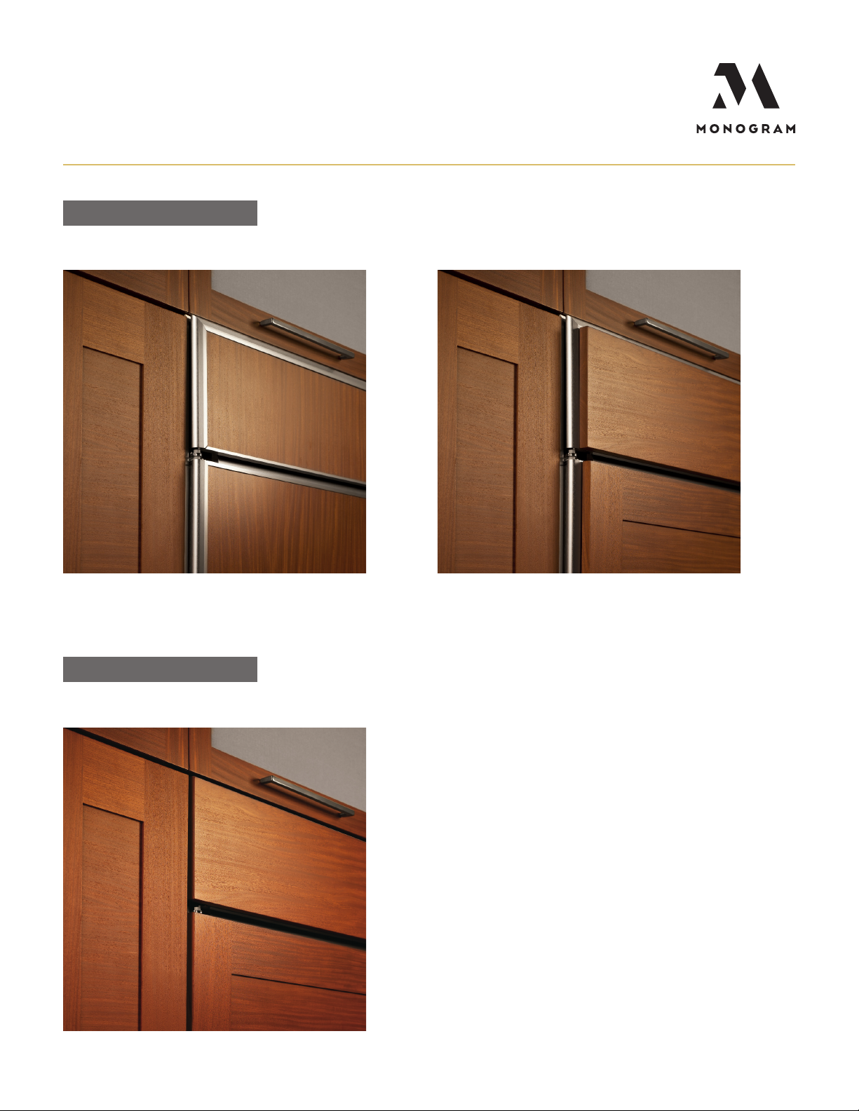
SECTION 1
STANDARD INSTALLATION
1/4" FRAMED PANELS
SECTION 2
3/4" OVERLAY PANELS
FLUSH INSET INSTALLATION
REQUIRES ADDITIONAL TRIM KIT ZKFN
For questions about your
appliance, please call 1-800-626-2000.
PAGE 2 OF 12
Product Specication Created 10/19
Page 3

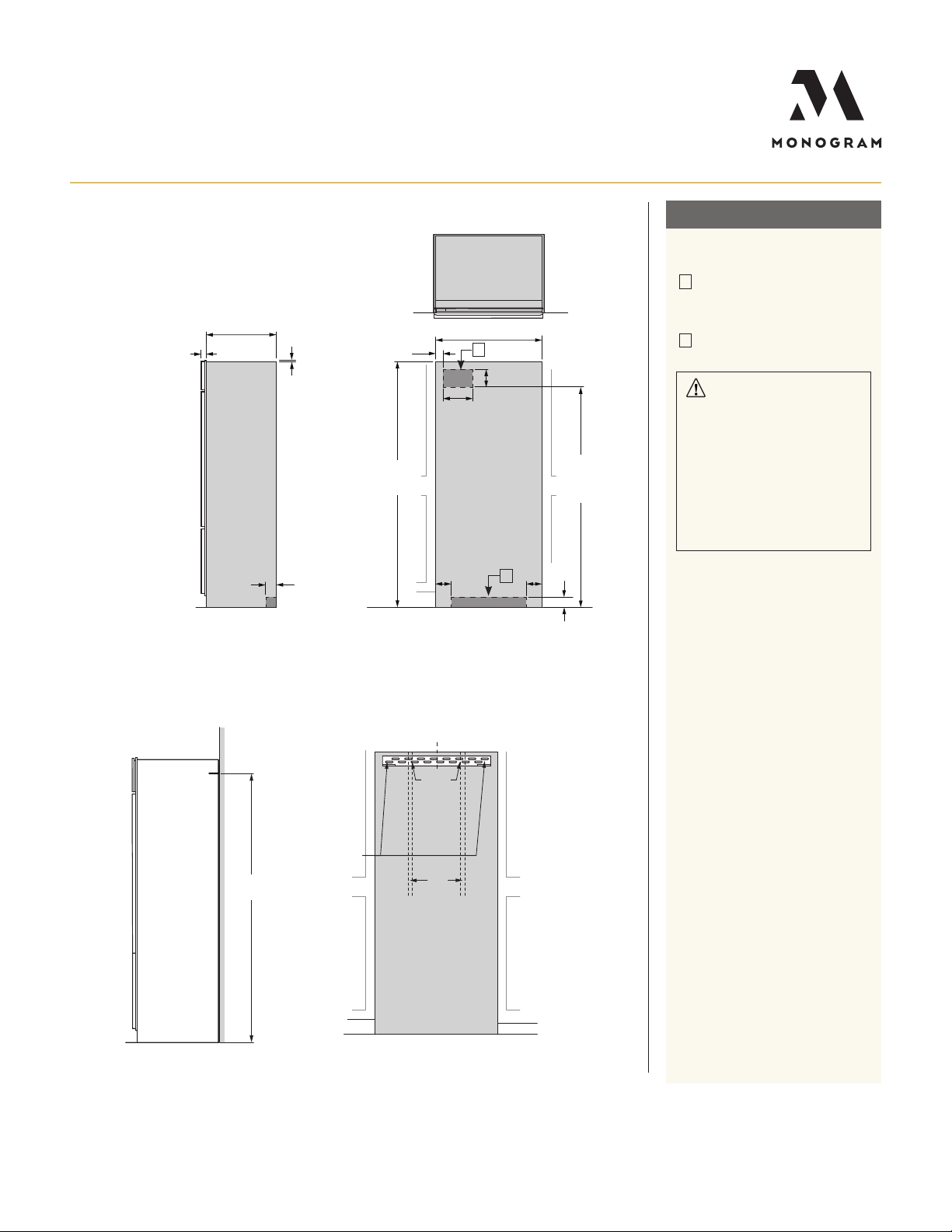
OVERALL DIMENSIONS
36" (91.4)
STANDARD INSTALLATION
25 3/8" (64.5)
23 5/8" (60.0)
10"
(25.4)
3/4"
(1.9)
SPECIFICATIONS
Overall Width 36" (91.4 cm)
Overall Height 84" (213.4 cm)
Overall Depth 25 3/8" (64.5 cm)
Door Clearance 18 1/2" (47 cm)
Cutout Width 35 1/2" (90.2 cm)
Cutout Height 84" (213.4 cm)
Cutout Depth 24" (61 cm)
Plumbing Requirements 1/4" OD copper tubing or
GE SmartConnect kit
Shipping Weight 670 lb (304 kg)
ATTENTION ELECTRICIAN:
A 115 volt 60Hz., 15 or 20 amp power supply is required. An
individual properly grounded branch circuit or circuit breaker
is recommended. Install a properly grounded 3-prong electrical
receptacle recessed into the back wall.
*84"
(213.4)
FRONT VIEW
*73 1/4"
(186.1)
*4 1/8"
(10.5)
* Shipping height. Use leveling legs and wheels for maximum 1"
height adjustment from shipping height.
35" (89.0)
Case width
**12 7/8"
(32.7)
4 9/16"
(11.6)
Allow 4" (10.2) min
clearance to wall for
90º door swing
**130° Door swing
Doors can be adjusted to
90° door swing
TOP VIEW
**12 7/8"
(32.7)
4 9/16"
(11.6)
Allow 4" (10.2) min
clearance to wall for
90º door swing
(SHOWING DOOR SWING)
** Dimensions based on custom handle height of 2 9/16" (6.5).
*83 1/2"
(212.1)
SIDE VIEW
18 3/16"
(46.2)
For questions about your
appliance, please call 1-800-626-2000.
Dimensions in parentheses a re in centimeters unless otherwise noted.
Actual product dimensions may vary due to ma nufacturing tolerances.
Product Specication Created 10/19PAGE 3 OF 12
Page 4
STANDARD INSTALLATION 3/4" PANELS
24" (61)
1 9/16"
(3.97)
7/16"
Trim overlap
(1.1)
2 5/16"
(5.874)
*84"
(213.4)
*Trim will overlap
additional 7/16"
TOP VIEW
35 1/2" (90.2)
ELEC.
10"
(25.4)
STANDARD INSTALLATION
HELPFUL TIPS
A
Mounting the junction box in this
location will also allow for front
accessibility through access panel.
B
A
6"
(15.24)
Water supply a rea.
WARNING:
e refrigerator is top heavy
and must be secured to prevent
the possibility of tipping forward.
75"
(190.5 )
From floor
to bottom
of electrical
area
Failure to do so may result in dea th
or serious injury.
e information below is for ca binet
design only. When installing the
anti-tip system you must use the
product installation instructions.
ANTI-TIP BRACKET
SIDE VIEW INSTALLED
WITH ANTI-TIP BRACKET
SIDE VIEW
81 1/2"
(207.0)
3 1/2"
(8.9)
additional hole
locations at end
Bracket
mounted
into vertical
wall studs
centered
within the
cutout
Ensure holes
selected are
Use two
of brackets
centered on
the studs
Studs
FRONT VIEW OF CUTOUT
WITH ANTI-TIP BRACKET
5"
(12.7)
WATERW
FRONT VIEW
C
L
Wall
3 1/2"
5"
(8.9)
(12.7)
B
e information below applies to all
installation constructions:
• A wall bracket, bolts and toggles will
be supplied with the unit.
• e bolts will be used to attach
bracket to wall in 4 locations. Two
of the locations must penetra te the
center of the wall studs.
• e toggles are used for sta bility in
drywall and when metal studs a re
encountered. Lag bolts are used in
wood studs.
• In installation opening, measure
81-1/2" from floor and draw a
horizontal line.
• Locate a nd mark the wall studs on
horizontal line. Verify at least two
studs have their centerlines within
the center 32-1/2" of installation
opening to ensure 2 wall studs are
penetrated.
• e bracket will be centered left
to right in opening with bottom of
bracket on the horizontal line.
• When unit is placed in opening, the
bracket tabs will align with openings
in back of the unit. e unit will be
secured to the bracket using supplied
“L” bolts.
See Installation Instructions for
detailed instructions.
For questions about your
appliance, please call 1-800-626-2000.
PAGE 4 OF 12
Product Specication Created 10/19
Page 5
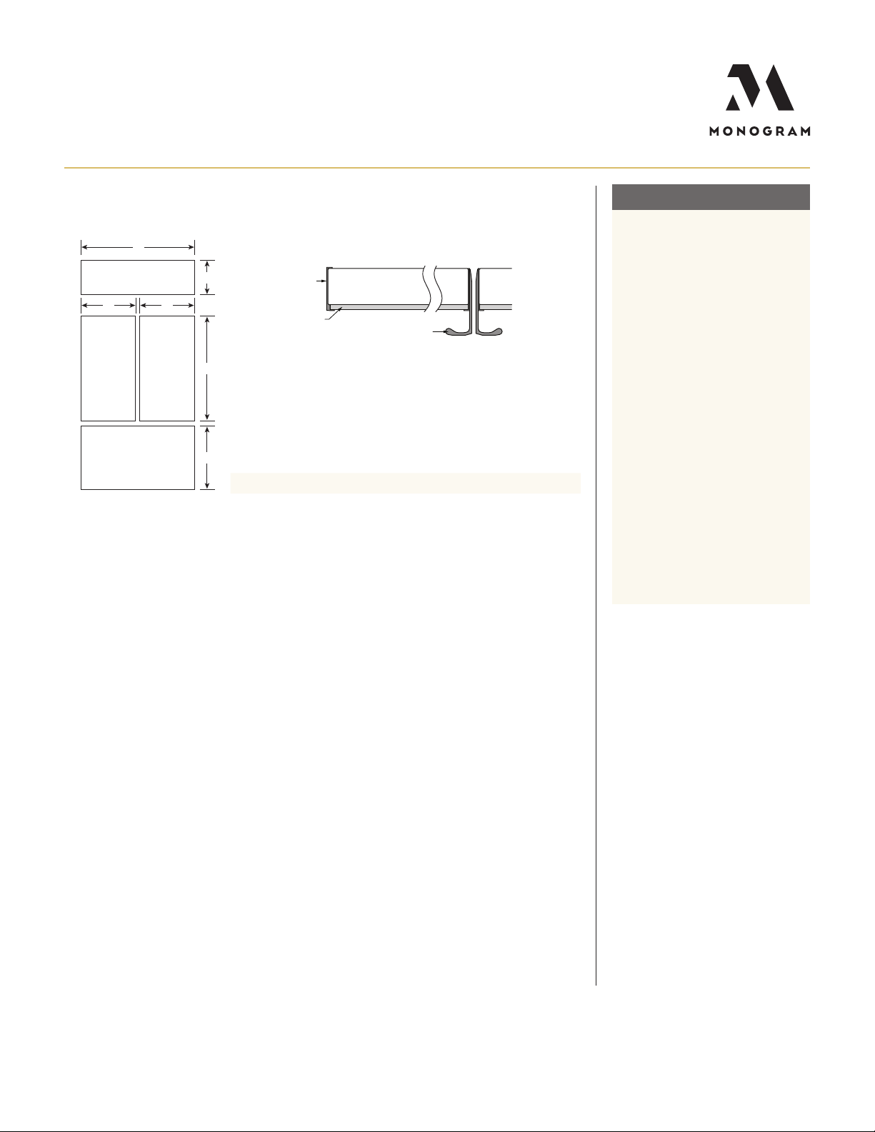
1/4" Framed Panel
STANDARD 1/4" FRAMED PANEL DIMENSIONS
A
Grille Panel
E E
PANEL ASSEMBLY CROSS SECTION
B
Trim
Door
STANDARD INSTALLATION
HELPFUL TIPS
Trimmed refrigerators a re designed
to be customized with decorative
panels Field-installed custom door
and grille pa nels are required.
Fresh
Food
Panel
Freezer Drawer Panel
Fresh
Food
Panel
Optional ZKLN kit handles
C
PANEL DIMENSIONS
D
A B C D E
1/4" Framed Panel 33 7/8" 8 7/8" 46 1/16" 21 7/8" 16 1/2"
1/4" FRAMED PANELS:
For 1/4" thick custom panels
ordered from your cabinet maker.
e decorative pa nels slide into
this trim.
MAXIMUM TOTAL PANEL
WEI GHT:
• Fresh food door panel – 30 lbs.
• Freezer drawer panel – 28 lbs.
• Grille panel – 11 lbs
DOOR HANDLES:
Door handles not included. Custom
handles supplied by your ca binet
maker may be used. Optional visor
handle kit ZKLN ava ilable.
For questions about your
appliance, please call 1-800-626-2000.
PAGE 5 OF 12
Product Specication Created 10/19
Page 6

A
STANDARD 3/4" OVERLAY PANEL DIMENSIONS
STANDARD INSTALLATION
PANEL ASSEMBLY CROSS SECTION
Grille Panel
E E
Fresh
Food
Panel
Fresh
Food
Panel
B
1/4" Backer Panel
.10" Spacer Panel
C
PANEL DIMENSIONS
1/4" Framed Panel 33 7/8" 8 7/8" 46 1/16" 21 7/8" 16 1/2"
Freezer Drawer Panel
D
.10" Framed Panel 32 1/2" 7 5/8" 44 11/16" 20 1/2" 15"
3/4" Overlay Panel 34 1/8" 9" 46 5/16" 22" 16 5/8"
.25" + .10" + .75" = 1.10" Total Panel Thickness
1/4" BACKER ASSEMBLY DIMENSIONS
Hinge Side
C
C
Trim
Optional ZKLN kit handles
Door
3/4" Overlay Panel
A B C D E
Grille Back
C
A B
HELPFUL TIPS
Trimmed refrigerators a re designed to
be customized with decorative pa nels
Field-installed custom door and grille
panels a re required.
3/4" OVERLAY PANELS:
For your 3/4" thick custom panels
ordered from your cabinet maker the
overlay panel must be secured to a
1/4"-thick backer panel which slides
into the trim. A spacer panel 0.10"
thick must be placed between the
overlay and backer pa nels.
Center each panel over the other.
Assemble the panels with glue a nd
screws. Screws must be countersunk
into the backer panel.
NOTE : Left-to-right offset is not
always equal to top-to-bottom offset.
MAXIMUM TOTAL PANEL
WEI GHT:
• Fresh food door panel – 30 lbs.
• Freezer drawer panel – 28 lbs.
• Grille panel – 11 lbs
DOOR HANDLES:
Door handles not included. Custom
handles supplied by your ca binet
maker may be used. Optional visor
D
handle kit ZKLN ava ilable.
Backer with
Overlay Panel
Assembly
Fresh Food
Back
B
1/4"
A
Overlay
Panel
Spacer
1/2"
.10"
Door
Backer
Panel
For questions about your
appliance, please call 1-800-626-2000.
Fresh Food
Back
A
B
DD
C
Freezer Drawer
A
B
D
PANEL DIMENSIONS
A B C D
Fresh Food Door Panels 1/8" 0 1/8" 1/8"
Freezer Drawer Panel 1/8" 1/8" 1/16" 1/16"
Grille Panel 1/8" 1/8" 1/16" 1/16"
PAGE 6 OF 12
Product Specication Created 10/19
Page 7
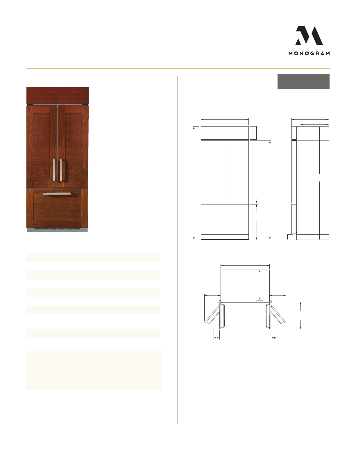
OVERALL DIMENSIONS
AFTER PANEL INSTALL
FLUSH INSET
INSTALLATION
SPECIFICATIONS
Overall Width
Overall Height
Overall Depth
Door Clearance
Cutout Width
Cutout Height
Cutout Depth
Plumbing Requirements
38" (96.5 cm)
84 1/2" (214.6 cm)
25 7/8" (65.9 cm)
19 1/2" (49.5 cm)
39" (99.1 cm)
85" (215.9 cm)
26 3/16" (66.5 cm)
1/4" OD copper tubing or
GE SmartConnect kit
Shipping Weight
670 lb (304 kg)
ATTENTION ELECTRICIAN:
A 115 volt 60Hz., 15 or 20 amp power supply is required. An
individual properly grounded branch circuit or circuit breaker
is recommended. Install a properly grounded 3-prong electrical
receptacle recessed into the back wall.
38" (96.5)
10 13/16"
(27.5)
*84 1/2"
(214.6)
* Shipping height. Use leveling legs and wheels for maximum
1" height adjustment from shipping height.
35" (88.9)
Case width
**8"
(20.3)
*115° Door swing
Doors can be adjusted to
90° door swing
4 9/16" (11.6) min
Allow
clearance to a wall for
90º door swing
** Dimensions based on custom handle height of 2 9/16" (6.5).
TOP VIEW
*73 1/4"
(186.1)
7/16"
(1.1)
*26 3/8"
(70.0)
20 5/8"
(52.5)
Allow 4 9/16" (11.6) min
clearance to a wall for
90º door swing
**8"
(20.3)
*4"
(10.2)
25 7/8" (65.7)
SIDE VIEWFRONT VIEW
19 1/2"
(49.5)
20 5/8" (52.4)
*83 1/2"
(212.1)
For questions about your
appliance, please call 1-800-626-2000.
Dimensions in parentheses a re in centimeters unless otherwise noted.
Actual product dimensions may vary due to ma nufacturing tolerances.
Product Specication Created 10/19PAGE 7 OF 12
Page 8

FLUSH INSET INSTALLATION 3/4" PANELS
FLUSH INSET INSTALLATION
FLUSH INSET KIT ZKFN REQUIRED
26 3/16" (66.5)
Flush inset depth
20 15/16" (53.2)
Depth to cleat
Finished cleats
85"
(215.9)
3 1/2"
W
ANTI-TIP BRACKET
81 1/2"
(207.0)
SIDE VIEW INSTALLED
WITH ANTI-TIP BRACKET
(8.9)
5 1/4" (13.3)
3/4" (1.9)
Width of side cleats
4 1/16"
85"
(215.9)
Use two
additional hole
locations at end
of brackets
TOP VIEW
Case
Finished cleats
Case Trim
3/4" Panel
Door
39" (99.1) Flush inset width
37 1/2" (95.3)
Width between cleats
6"
(15.2)
(11.0)
ELEC.
10"
(25.4)
B
7"
(17.8)
7"
(17.8)
B
WATER
FRONT VIEWSIDE VIEW
C
L
Bracket
mounted
into vertical
wall studs
centered
within the
cutout
Ensure holes
selected are
centered on
the studs
Wall
Studs
FRONT VIEW OF CUTOUT
WITH ANTI-TIP BRACKET
1/2" (1.3)
75 1/2"
(191.8 )
From floor
to bottom
of electrical
3 1/2"
(8.9)
area
HELPFUL TIPS
A
Mounting the junction box in this
location will also allow for front
accessibility through access panel.
B
Water supply a rea
A
WARNING:
e refrigerator is top heavy a nd
must be secured to prevent the
possibility of tipping forward.
Failure to do so may result in
death or serious injury.
e information below is for ca binet
design only. When installing the antitip system you must use the product
installation instructions.
e information below applies to all
installation constructions:
• A wall bracket, bolts and toggles will
be supplied with the unit.
• e bolts will be used to attach
bracket to wall in 4 locations. Two
of the locations must penetra te the
center of the wall studs.
• e toggles are used for sta bility in
drywall and when metal studs a re
encountered. Lag bolts are used in
wood studs.
• In installation opening, measure
81-1/2" from floor and draw a
horizontal line.
• Locate a nd mark the wall studs on
horizontal line. Verify at least two
studs have their centerlines within
the center 32-1/2" of installation
opening to ensure 2 wall studs are
penetrated.
• e bracket will be centered left to
right in opening with bottom of
bracket on the horizontal line.
• When unit is placed in opening, the
bracket tabs will align with openings
in back of the unit. e unit will be
secured to the bracket using supplied
“L” bolts.
See Installation Instructions for
detailed instructions.
For questions about your
appliance, please call 1-800-626-2000.
Product Specication Created 10/19PAGE 8 OF 12
Page 9

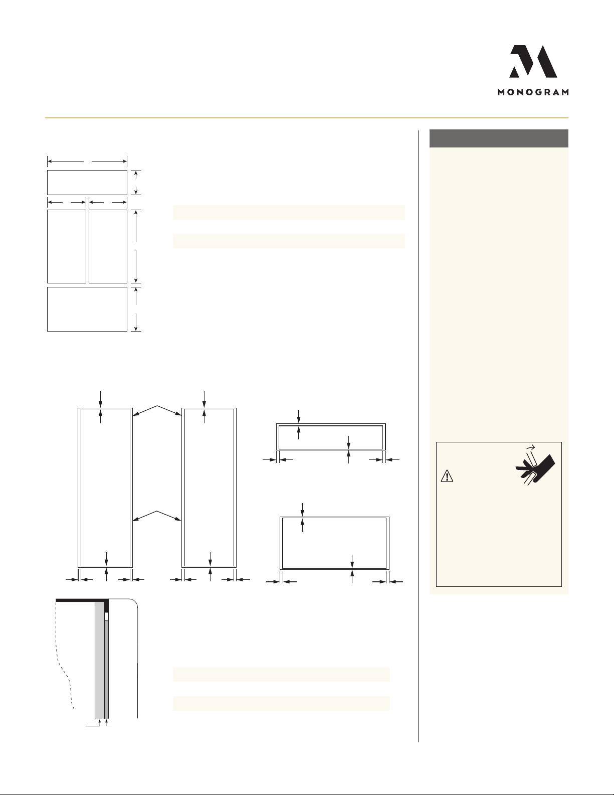
FLUSH INSET 3/4" PANEL DIMENSIONS
FLUSH INSET INSTALLATION
A
Grille Panel
E E
B
PANEL DIMENSIONS
A B C D E
Fresh
Food
Panel
Freezer Drawer Panel
Fresh
Food
Panel
C
D
38" 10 13/16" 46 7/16" 22 3/8" 18 3/4"
3/4" RAISED FRESH FOOD DOOR PANELS ROUTING
11/32"
1/4"
DETAIL TOP
3/4"
1/4"
7/16"
NOTE: Routed areas should
be finished as they may be
visible when assembled.
Front
TOP
HELPFUL TIPS
Trimmed refrigerators a re designed
to be customized with decorative
panels. Field-installed 1/2" or 3/4"
custom door, drawer and grille
panels a re required. For 3/4" raised
panels, routing is required. e router
depth is 1/4" all the way around
the panel’s backs. Additional pa nel
width reductions are required per
the diagrams shown. is will crea te
“picture frame’ routing allowing the
panels to slide into the a ttached door,
drawer and grille trims.
MAXIMUM TOTAL PANEL
WEI GHT:
• Fresh food door panels – 30 lbs.
• Freezer drawer panel – 28 lbs.
• Grille panel – 11 lbs
NOTE : For panels constructed with
rails a nd stiles (5-panel), the rails must
be a minimum of 3” wide a nd stiles
must be a minimum of 4” wide.
DOOR HANDLES
Door handles not included. Custom
handles supplied by your ca binet
maker may be used.
Back
1/4"
CORNER VIEW SHOWING
DETAIL BOTTOM
HINGE SIDE HANDLE SIDE
ROUTER DEPTH 1/4" ROUTER DEPTH 1/4"
2 1/16"
LEFT
SIDE
3/4" PANEL BOTTOM VIEW
(AFTER ROUTING)
“PICTURE FRAME” ROUTING
Front
Back
For questions about your
appliance, please call 1-800-626-2000.
RIGHT
SIDE
3/16"
FrontBack
BOTTOM
3/4" PANEL SIDE VIEW
(AFTER ROUTING)
WARNING:
Door Trim Pinch Point Haza rd
Improper installation ca n lead to a
finger pinch point haza rd between
the side door trim and the ca binets
when operating the door, especially
with children. To minimize this risk
you must follow the installation
instructions for cabinet dimensions,
trim assembly and door stop a ngle.
Product Specication Created 10/19PAGE 9 OF 12
Page 10

3/4" RAISED FREEZER DRAWER PANEL ROUTING
TOP
DETAIL TOP
11/32"
LEFT SIDE
3/4"
1/4"
1/4"
DETAIL BOTTOM
DETAIL
ROUTER DEPTH 1/4"
2 1/16" 2 1/16"
LEFT
SIDE
1/2"
1/4"
3/4" PANEL BOTTOM VIEW
(AFTER ROUTING)
NOTE: Routed areas should
be finished as they may be
visible when assembled.
Back
CORNER VIEW SHOWING
“PICTURE FRAME” ROUTING
Front
Back
ROUTER DEPTH 1/4"
3/4" RAISED GRILLE PANEL ROUTING
Front
DETAIL RIGHT
SIDE
RIGHT
SIDE
TOP
FrontBack
BOTTOM
3/4" PANEL SIDE VIEW
(AFTER ROUTING)
FLUSH INSET INSTALLATION
HELPFUL TIPS
Trimmed refrigerators a re designed
to be customized with decorative
panels. Field-installed 1/2" or 3/4"
custom door, drawer and grille
panels a re required. For 3/4" raised
panels, routing is required. e
router depth is 1/4" all the way
around the pa nel’s backs. Additional
panel width reductions a re required
per the diagrams shown. is will
create “picture fra me’ routing
allowing the panels to slide into the
attached door, drawer a nd grille
trims.
MAXIMUM TOTAL PANEL
WEIGHT:
• Fresh food door panels – 30 lbs.
• Freezer drawer panel – 28 lbs.
• Grille panel – 11 lbs
NOTE : For panels constructed with
rails a nd stiles (5-panel), the rails
must be a minimum of 3” wide a nd
stiles must be a minimum of 4” wide.
DOOR HANDLES
Door handles not included. Custom
handles supplied by your ca binet
maker may be used.
DETAIL TOP
ROUTER DEPTH 1/4"
1 11/16"
LEFT SIDE
1/4"
DETAIL BOTTOM
LEFT
SIDE
For questions about your
appliance, please call 1-800-626-2000.
NOTE: Routed areas should
be finished as they may be
visible when assembled.
Front
Back
CORNER VIEW SHOWING
“PICTURE FRAME” ROUTING
DETAIL
ROUTER DEPTH 1/4"
2 1/16" 2 1/16"
Front
Back
3/4" PANEL BOTTOM VIEW
(AFTER ROUTING)
DETAIL RIGHT
SIDE
ROUTER DEPTH 1/4"
RIGHT
SIDE
FrontBack
BOTTOM
3/4" PANEL SIDE VIEW
(AFTER ROUTING)
Product Specication Created 10/19PAGE 10 OF 12
Page 11

FLUSH INSET INSTALLATION 1/2" PANELS
FLUSH INSET INSTALLATION
FLUSH INSET KIT ZKFN REQUIRED
26 3/16" (66.5)
Flush inset depth
20 13/16" (52.9)
Depth to cleat
Finished cleats
85"
(215.9)
W
ANTI-TIP BRACKET
81 1/2"
(207.0)
3 1/2"
(8.9)
5 3/8" (13.7)
3/4" (1.9)
Width of side cleats
4 1/16"
85"
(215.9)
Use two
additional hole
locations at end
of brackets
TOP VIEW
Finished cleats
Case Trim
1/2" Panel
39" (99.1) Flush inset width
Width between cleats
ELEC.
(11.0)
7"
(17.8)
(25.4)
FRONT VIEWSIDE VIEW
Ensure holes
Case
Door
37 1/2" (95.3)
10"
WATER
C
L
Bracket
mounted
into vertical
wall studs
centered
within the
cutout
selected are
centered on
the studs
Wall
Studs
6"
(15.2)
B
7"
(17.8)
1/2" (1.3)
75 1/2"
(191.8 )
From floor
to bottom
of electrical
3 1/2"
(8.9)
area
HELPFUL TIPS
A
Mounting the junction box in this
location will also allow for front
accessibility through access panel.
B
Water supply a rea
A
WARNING:
e refrigerator is top heavy a nd
must be secured to prevent the
possibility of tipping forward.
Failure to do so may result in
death or serious injury.
e information below is for
cabinet design only. When installing
the anti-tip system you must use the
product installation instructions.
e information below applies to
all installation constructions:
• A wall bracket, bolts and toggles will
be supplied with the unit.
• e bolts will be used to attach
bracket to wall in 4 locations. Two
of the locations must penetra te the
center of the wall studs.
• e toggles are used for sta bility in
drywall and when metal studs a re
encountered. Lag bolts are used in
wood studs.
• In installation opening, measure
81-1/2" from floor and draw a
horizontal line.
• Locate a nd mark the wall studs on
horizontal line. Verify at least two
studs have their centerlines within the
center 32-1/2" of installation opening
to ensure 2 wall studs are penetra ted.
• e bracket will be centered left to
right in opening with bottom of
bracket on the horizontal line.
• When unit is placed in opening, the
bracket tabs will align with openings
in back of the unit. e unit will be
secured to the bracket using supplied
“L” bolts.
See Installation Instructions for
detailed instructions.
SIDE VIEW INSTALLED
WITH ANTI-TIP BRACKET
For questions about your
appliance, please call 1-800-626-2000.
FRONT VIEW OF CUTOUT
WITH ANTI-TIP BRACKET
Product Specication Created 10/19PAGE 11 OF 12
Page 12
FLUSH INSET 1/2" PANEL DIMENSIONS
A
Grille Panel
E E
B
PANEL DIMENSIONS
1/4" Backer Panel
.10" Space Panel 32 1/2" 7 5/8" 44 11/16" 20 1/2" 15"
Fresh
Food
Panel
Freezer Drawer Panel
Fresh
Food
Panel
C
D
1/2" Overlay Panel 38" 10 13/16" 46 7/16" 22 3/8" 18 3/4"
1/4" BACKER ASSEMBLY DIMENSIONS
A B C D E
33 7/8" 8 7/8" 46 1/16 21 7/8" 16 1/2"
FLUSH INSET INSTALLATION
HELPFUL TIPS
e 1/2" overlay panel must be
secured to a .10" spacer pa nel and a
1/4" thick backer panel, which slides
into the trim.
ASSEMBLE THE PANELS
WITH GLUE AND SCREWS:
• Center the spacer panel on the
backer panel, left to right a nd top to
bottom. Secure the panels with glue.
• Refer to the chart for loca ting the
backer panel to the overlay pa nel.
Secure the overlay panel to the
backer panel with glue a nd screws.
Screws must be countersunk into
the backer panel.
MAXIMUM TOTAL PANEL
WEI GHT:
• Fresh food door panel – 30 lbs.
• Freezer drawer panel – 28 lbs.
• Grille panel – 11 lbs.
Hinge Side
NOTE: For pa nels constructed with
rails a nd stiles (5-panel), the rails
C
C
Grille Back
C
A B
D
must be a minimum of 3" wide a nd
stiles must be a minimum of 4" wide.
WARNING:
Backer with
Overlay Panel
Assembly
Door Trim Pinch Point Haza rd
Improper installation ca n lead to a
finger pinch point haza rd between
Fresh Food
Back
Fresh Food
Back
C
Freezer Drawer
the side door trim and the ca binets
when operating the door, especially
with children. To minimize this risk
you must follow the installation
instructions for cabinet dimensions,
B
A
A
B
DD
A
B
D
Door
1/2"
Overlay
Panel
PANEL DIMENSIONS
trim assembly and door stop a ngle.
A B C D
Fresh Food Door Panels 2 1/16" 3/16" 3/16" 3/16"
Freezer Drawer Panel 2 1/16" 2 1/16" 1/4" 1/4"
Grille Panel 2 1/16" 2 1/16" 1 11/16" 1/4"
1/4"
Backer
Panel
.10"
Spacer
For questions about your
appliance, please call 1-800-626-2000.
Product Specication Created 10/19PAGE 12 OF 12
 Loading...